17. Mechanical design, machine design
Amsterdam May 27, 2020
To do
| Description | status |
|---|---|
| Group assignment | done |
| Document group assignment | done |
| Document your individual contribution to the group assignment | done |
Source files
All source files can be found on the group page.
urls
| Description | link |
|---|---|
| Index of this week’s topic (one for mechanical design, one for machine design | http://academy.cba.mit.edu/classes/mechanical_design/index.html http://academy.cba.mit.edu/classes/machine_design/index.html |
| Global lecture video | https://vimeo.com/423606237 |
| Global review video | https://vimeo.com/425604692 |
| Group assignment | https://fabacademy.org/2020/labs/waag/groupAssignments/week17.html |
| Recitation on machines | https://vimeo.com/424899829 |
This week is a group assignment so most of it is documented on the communual group page. On this page is documented what I contributed.
Building the FabConnector
Our group
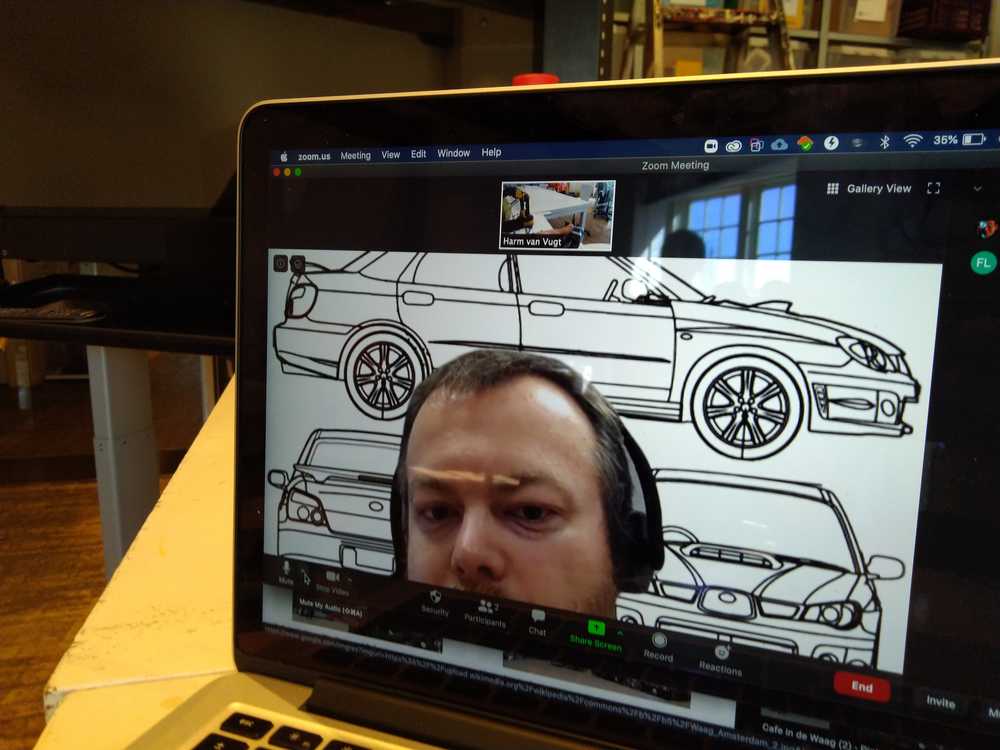
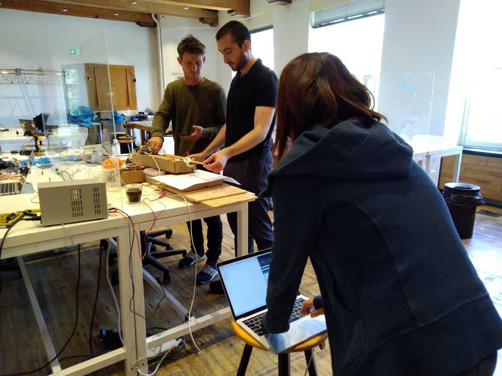
For the group assignment we are collaborating regionally. FabLab AgriLab in France and FabLab Waag in Amsterdam have joined forces to create a machine together. This is the setup for the collaboration.
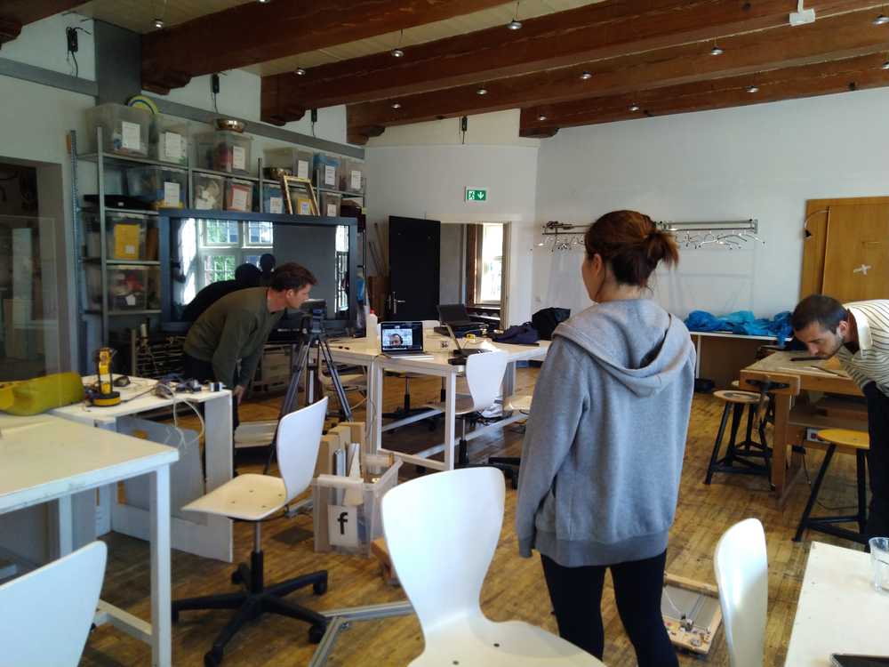
Picture taken in the Waag. Florent from AgriLab joins via videoconference.
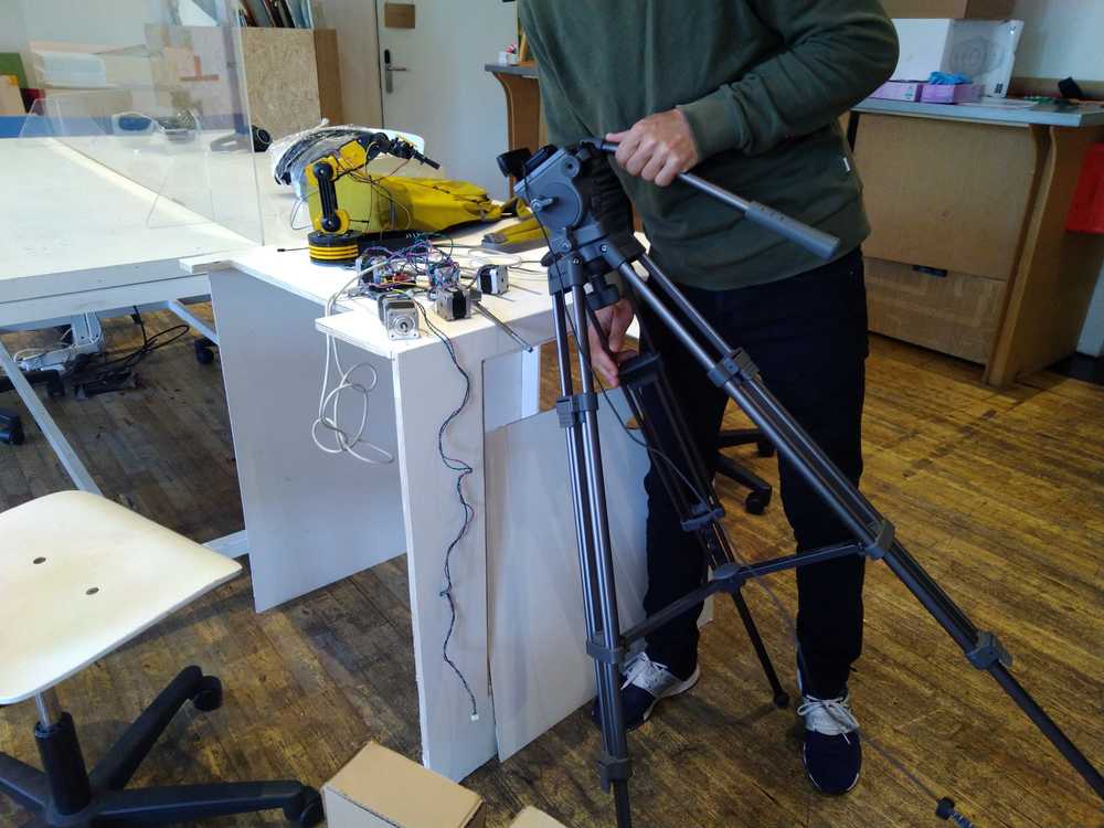
Showing the goods. So many stepper motors!
Florent is eying the stepper motors critically.
The assignment
- design a machine that includes mechanism+actuation+automation
- build the mechanical parts and operate it manually
- document the group project and your individual contribution
- actuate and automate your machine
- document the group project and your individual contribution
Our ideas
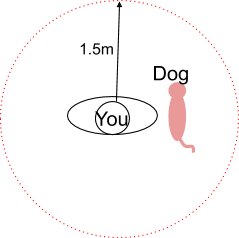
Dog project
What it does
1. Follow the RF controller owner
2. Keep the distance from RF controller owner
3. If anyone comes closer than 1.5m, it makes sounds and runs away

Autonomous following systems
Keep the distance
Ultrasonic Sensor (>3 meter inside/outside) - we have 4 HC-SR04 (Harm used it)
Dopler sensor - 7 meter outside/inside? - we have 4 (RCWL-0516) - Hyejin used this
Infrared sensor/transmitter (30 cm outside)
RFID (30cm?)
Recognizing the ‘owner’
- Following the phone Bluetooth? (Beacons)
- Shape/color recognition
- Color sensor
- Shape recognition https://pixycam.com/
- Follow your phone (in your pocket) Bluethooth (esp32 distance tracking)
- Hold/wear a specific IR light (leach/bracelet)
- you can set the pulse in a specific pulse mode so the dog won’t be fooled by the sunlight.
Power supply
5volt for the Arduino/Microcontroller
12 volt for the motors ?
1 - 2 amps? LiPo (light and powerful) is best? Easy = rechargeable AA
Structure
Must be rigid enough. Wood? (Composite?)
Face (fur/outside)
Pink fur?

Remote control
Rc: simple serial connection, simple
Wifi: send input on the network.
Idea 2
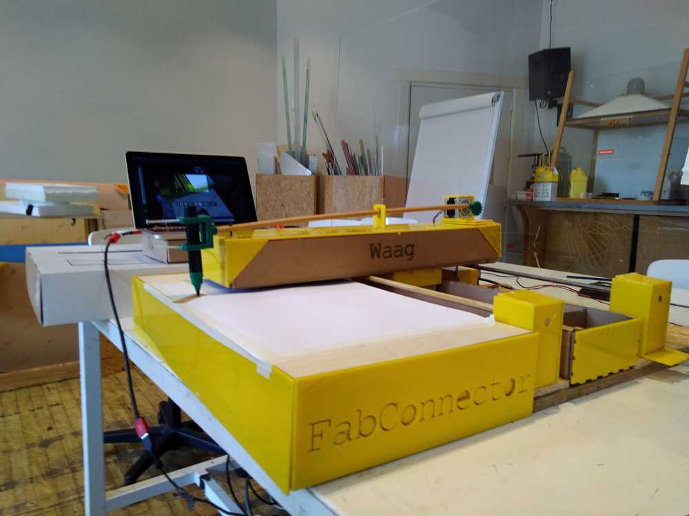
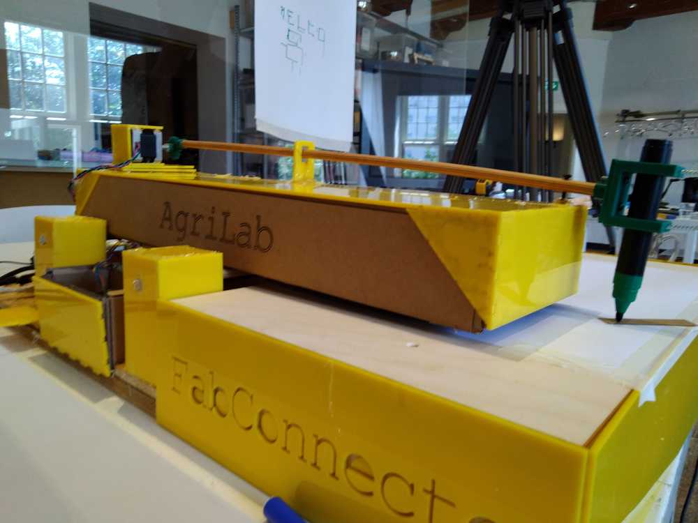
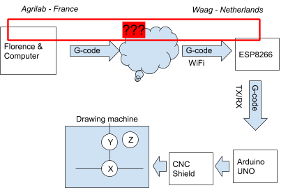
FabConnector: Drawing machine that can be operated remotely over the internet. Florent in France will move the drawing machine in Amsterdam.
A pen or pencil is attached to two arms. The arms are moved over X and Y axes by stepper motors. Since our group is geographically separated our project must of course include remote operation using networking. The first iteration of the machine will consist of drawing with pen aon paper. Second iteration, replace paper with sand. Third iteration: a way to flatten the sand for a new picture automatically.
Spiral development
- Spiral: pen and paper remotely operated
- Spiral: sand drawing
- Spiral: Cleaning the slate: flatten the sand
- Spiral: Image recognition: draw an image uploaded over the internet.
- Spiral: Drawing an image from a web cam picture.
- Spiral: Making it bigger for awe effect.
- Spiral: Make a hardware remote control.
- Spiral: Skynet: Making it sentient and control the world.
Requirements first spiral
Mechanism for X/Y/Z
Stable frame to hold it all together.
Control the stepper motors: Arduino with a stepper shield.
Find a way to lift the pen up and down.
Connect Arduino to ESP32 or Node MCU.
Nice packaging or casing.
Florent commented that if we use G-Code the machine needs to know its origin. That makes it more difficult. Just sending commands is easier.
Possible names for the project
LabConnector
Drawing battle
Bulletin Board
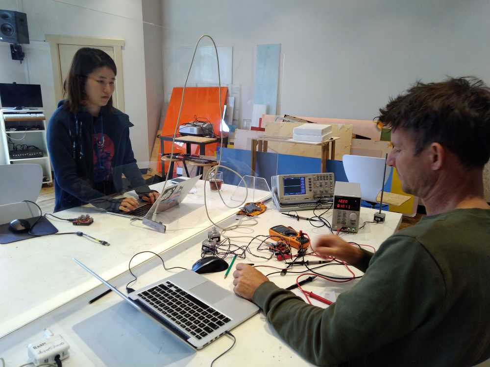
electronics and networking
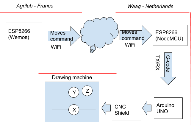
Here is an overview of the electronics and networking part of the system:
Finding the range and add end stops
Range: We brought the X-axis very close to the stepper motor. From there we guessed it’s range to be 800. We enter G1 X800 F3000 into the serial monitor. The X- moved to close to the end. There is still a little length left on the threaded rod of the X-axis. But we decide that we will place the end-point here. This allows for a little bit of leeway for things to go wrong. So we have determined the range at 40cm which translates the value 800 in G-code. We assume that the range for the Y-axis is the same.
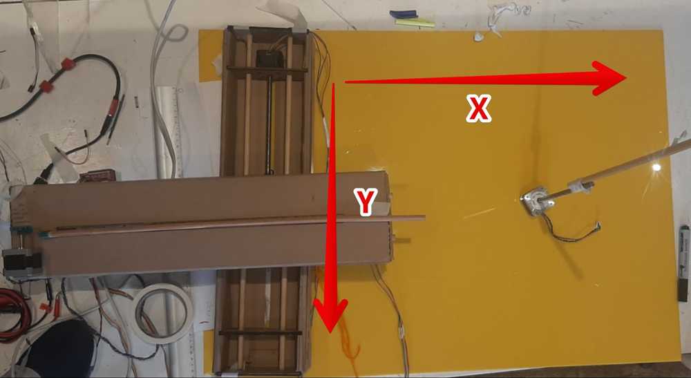 Beginning and end points of the X and Y axes.
Next up we are going to make physical end points. We will add buttons on the end of the axis. There are pins on the CNC shield that are called end stops. It has six of them: Z+, Z-, X+, X+,Y+, Y-.
We will connect the pins to a button. When our machine’s axis reaches its end point, it will physically push the button. This will send a signal to the CNC shield that the end stop has been reached.
First test:
We connect the computer directly to the Arduino, rather than having the NodeMCU in between. This makes it easier to do tests.
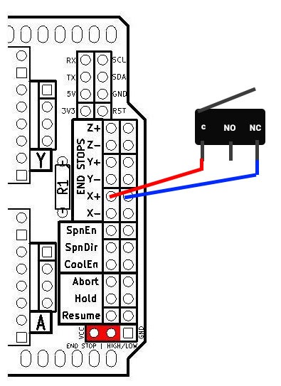
If you want to know more about this schematic you can look at this post. It shows pictures of an actual setup with Arduino and buttons. https://github.com/gnea/grbl/wiki/Wiring-Limit-Switches
The schematic shows the pinout of the end stops. We did the following and expected it to work. We connected one wire to both the pins highlighted in the picture. We then moved the X-axis. If we pulled one side of the wire off one of the pins, it simulates a button being pressed. We tested this but the X-axis did not stop. Source for this experiment is this page.
Next we looked at this video. This person connects the wires in the same way we did. But they also give GRBL commands (the library on the CNC shield. Here is an overview of all the GRBL commands. You can enter the commands through the serial monitor. The command is called Hard Limits (Enable/Disable). It “requires limit switches be installed and looks for one of the limit switches to be activated which triggers “Alarm” mode. In this mode, all machine motion, the spindle and coolant are shutdown .“. The command is: $21=0 where 0 is deactivated and 1 is activated.
But this also did not work.
We then decided to abandon this quest. It is not the most important part of the machine. We can zero the exis by resetting the Arduino and keep them in mind when operating the machine. Of course it will be much better to have end stops but for spiral development more important is to get the machine to work in the first place.
So for now we are going to work on a more important spiral: testing if Florent can send g-code from France to steer the machine. Once we know that that is working we can go back to the end point spiral.
Making a connection between France and the Netherlands
We try to get data from France to the CNC machine. For this we have to open a port at the Amsterdam side. We first need to find the IP address of the NodeMCU.
1. We uploaded a simple Wifi code to get the Node on the wifi network.
2. Got feedback from the NodeMCU
WiFi connected
13:49:19.091 -> IP address:
13:49:19.091 -> 10.1.3.240
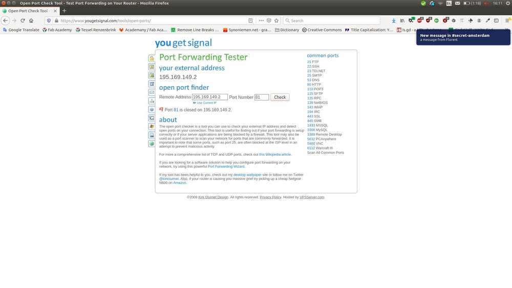
We then looked up the IP address of the Waag. Because Florent needs it to find us over the internet. You can find out your IP address via this website: https://www.whatismyip.com/. We used that IP address and asked Henk to open a port. He opened port 81 So Henk is forwarding 195.169.149.2 (our Waag connection) port 81 to NodeMCU (10.1.3.240) on port 80
We used this online tool to check if the socket is open. It scans if the port is open. But Henk told us not to use a port scanner. It triggers the firewall of the Waag network and closes the port. Henk told us that after some trial and error. Oops!
Henk explained how the networking setup works:
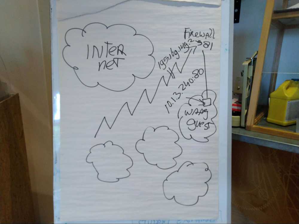
Outside is the global internet
The little clouds are the Waag network. It has multiple subnets.
Florent contacts us via the 195.xxxx IP-adress.
Henk made a little hole in the firewall for Florent to enter through. And he reaches port 81. (We don’t use port 80 because port 80 is always already occupied.). This port 81 communicates to IP-address 10.13.240 on port 80. This is the IP-address of the NodeMCU.
Us people on the Waag are already within the Waag network. So should we want to connect to the NodeMCU we use the 10.13.240:80 IP address should we want to address it. So we could test if the NodeMCU is visible in our own network. By entering the ip address in the address bar of a browser it worked.
Port forwarding Florent will find us via the IP-address and will attempt to connect to the opened port.
Florent will talk to port 81 coming from the outside wide internet. But internally we use port 80. So port 81 receives data from Florent and port 81 will talk to our internal port 80.
Florent sent a code. We did some remote debugging. And got a final code working: https://drive.google.com/drive/folders/1jWjuOo6egFrY4rYYGUkDqUeBkY79FpwW?usp=sharing
G-Code TX/RX
We were trying to send g-code over the NodeMCU. This did not work at first. One problem is that the response from the NodeMCU in the serial monitor is gibberish. Then we connected one computer to the Arduino Shield and the other to the NodeMCU. This way the Arduino-connected computer received input from the shield that was actually readable.
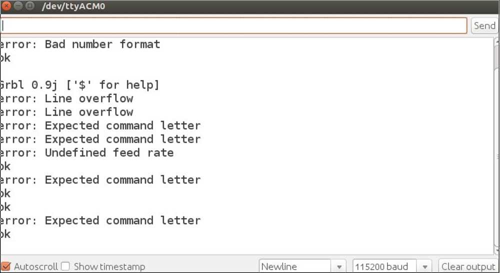
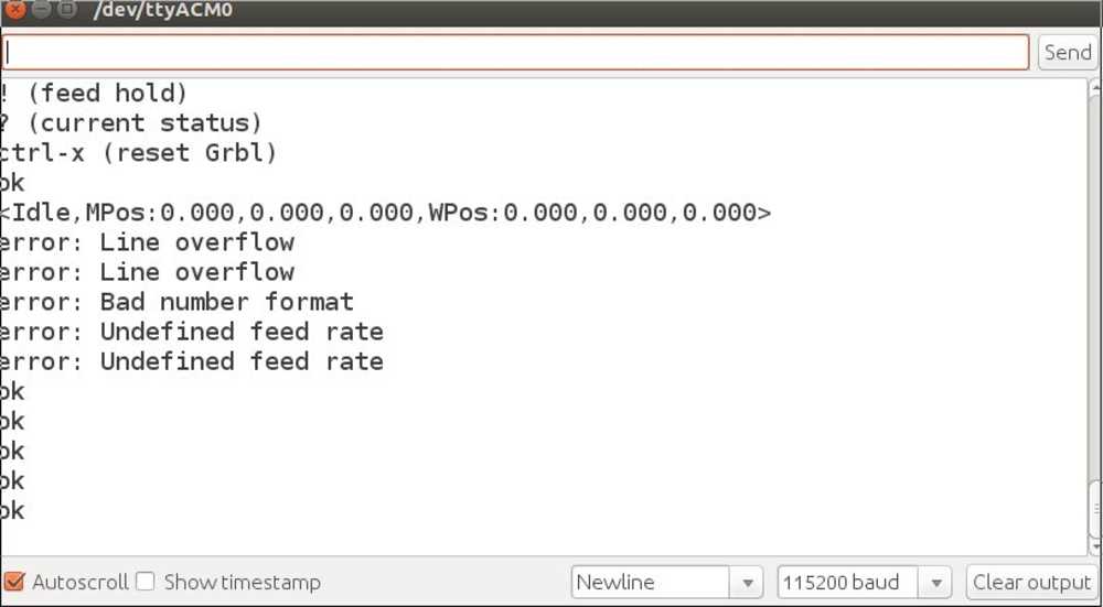
We could now read the error messages and could see there is a line overflow. After giving one command to the machine, there was immediately another. This led to line overflow. We added a delay after each line and now it works.
Code:
while (mySerial.available())
    Serial.write(mySerial.read());
  mySerial.write("G1 F3000\n");
  delay(500);
  while (mySerial.available())
    Serial.write(mySerial.read());
  mySerial.write("G1 X40 Y40\n");
  delay(3000);
while (mySerial.available())
    Serial.write(mySerial.read());
  delay(3000);
  mySerial.write("G1 X10 Y10\n");
  while (mySerial.available())
    Serial.write(mySerial.read());
  delay(3000);
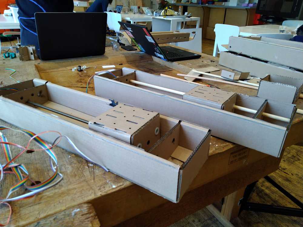
Building the platform
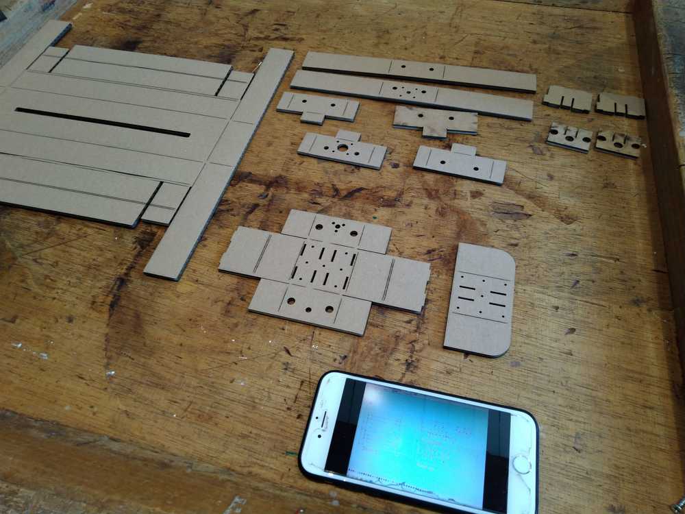
Lot’s of parts but no manual.
We figured it out.
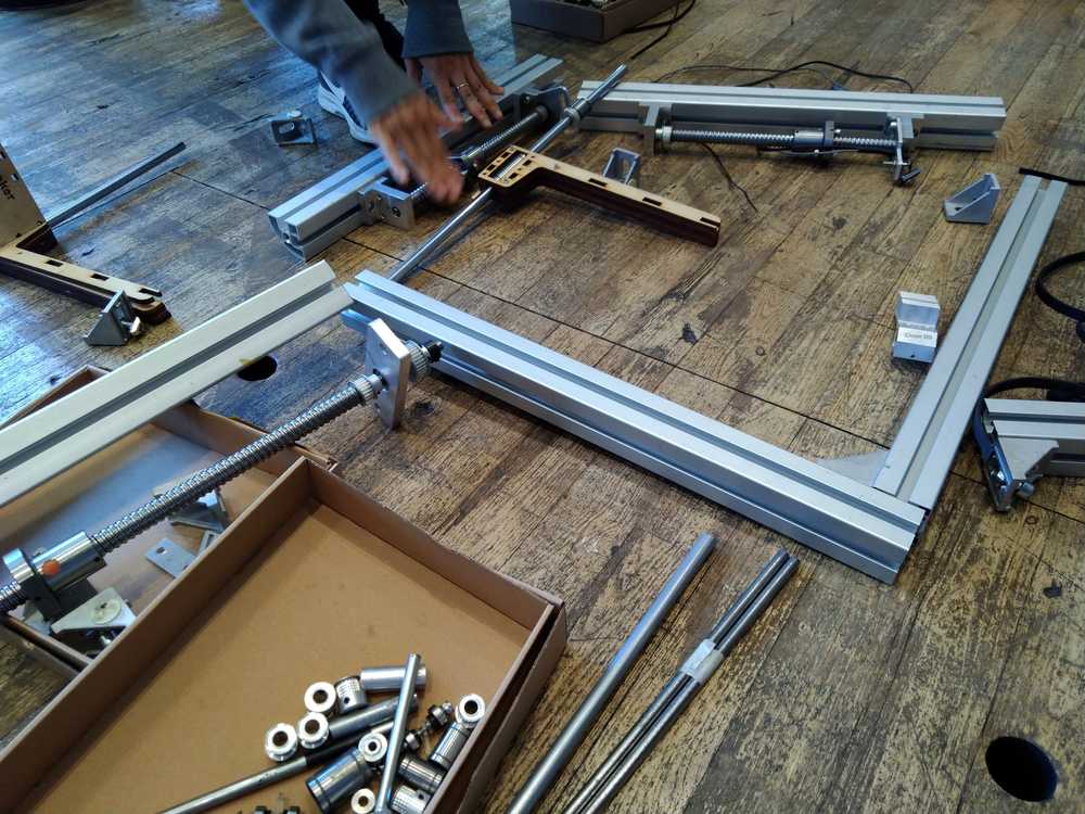
We will use these parts to make the X and Y axes. Nathan and I will create the frame to hold them. First we will create the frames to hold the two axes. After that we will move on to create the bed of the machine and a frame to hold it all together.
One idea to hold the X/Y axus is a bridge or upside-down U-form. It needs to be sturdy enough to hold the axes and it needs a steady base so as not to topple over.
But first we will make the frames for the axes. We will use this example to start from. You can download it on the MIT site.
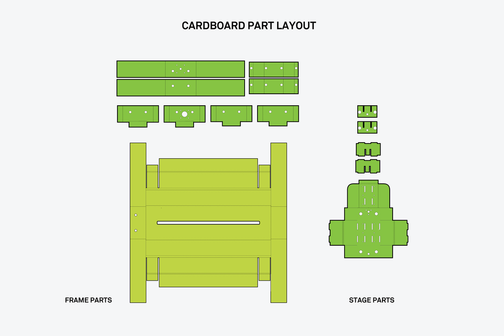
This is made by Nadya Peek. She makes machines and casings that are easy to use. Even for people without much experience or huge machines at their disposal. Then on Monday during the recitation on machines she was actually one of the presenters! :) So we got to thank her for her wonderful design.
We downloaded the example file from MIT. There are different one’s available on the website so go there to choose the one that fits your work environment best.
Nathan added the file in photoshop and removed the fill-in colors that aren’t necessary.
There are two types of lines in the design. The striped lines are folding lines. The laser cutter musn’t cut them but only engrave them. The whole lines must be cut.
When running the design through Illustrator and turning it into vectors, the dotted lines disappeared. So Nathan went back to photoshop and turned the striped lines into red lines.
Then we found other files in which the striped and dotted lines were already made in blue and red.
We ran a test run on the laser cutter. Not to waste cardboard we made the design 4 times smaller.
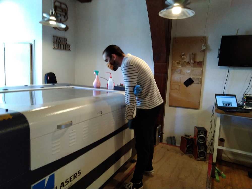
For the cutting trace we set settings to power 100, speed 100.
For the engraved trace: power 45, speed 100.
The cutting went alright but for the dotted lines the settings were too high. The laser cut right through instead of just making a folding cut. We tried again at power 15, speed 100 and that did work.
Triple cardboard: power 15, speed 100
This is how the test came out. Layed out in the way of the source file
We then proceeded to use 2-layered cardboard to make the real size frame. But then we found a new obstacle. We wanted to fold the model together but some dimensions were a little bit off. We then realized the original is done with 1-layer cardboard. So we then used one layered cardboard that was available and wanted to lasercut again. But now the lasercutter would not work. The laser would shortly blink and then stop sending laser light. Henk helped debug the machine. We then realized the power was set to 5. But the laser won’t come on at settings below power 10 to 12. So that was solved.
Folding the design took some figuring out.
Finished the frame of the X/Y arms
Meanwhile Hyejin and Harm are figuring out the servo motor/stepper motor problem.
Getting the pen down / moving the Z-axis
The X and Y axes are two stepper motors with threaded rods on them. But the Z-axis is different. It is used to put the pen up and down. The pen must be lifted up in order to have gaps between lines. Since the servo is really heavy and an overkill for just moving a pen up and down we looked into other methods of doing it. Hyejin and Harm tried to get a servo running using the stepper motor drive shield.
They managed to rotate a servo a bit on the G-code Z-axis command. But the servo had no power and felt out of control. So we abandoned the servo plan.
Instead the Z axis will also be made to move with a stepper motor.
Supporting structure
Next up is the bed of the machine and the rest of the supporting structure.
The pen must be lifted up in order to have gaps between lines. We tried using a servo motor to do that. That is difficult because we are using a Arduino shield for stepper motors. Hyejin and Harm did get a servo motor to work but it was not rotating as it should. Therefore it is easier to use a stepper motor. But if you place a stepper motor at the end of the axis arm, it is much too heavy. It will topple over.
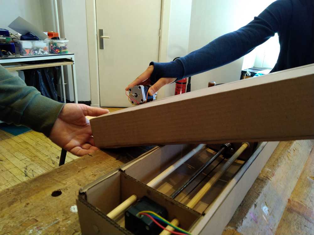
Therefore the better solution is to lift the entire arms structure.
So for the rest of the structure we have to do a couple of things:
1. Create the bed of the machine and a way to fasten the paper.
2. Find a way to lift the arm. We are considering a lever.
3. Put the lower arm in a box-like structure so the casing won’t move.
4. We will also add an acrylic box around the cardboard frame.
5. And we want to make a plate to connect the two boxes together.
Keep in consideration the length and width the pen will move. Outside of those lines you can build stuff like the box of for the lower arm.
First pen down system. Rotating the Z stepper motor
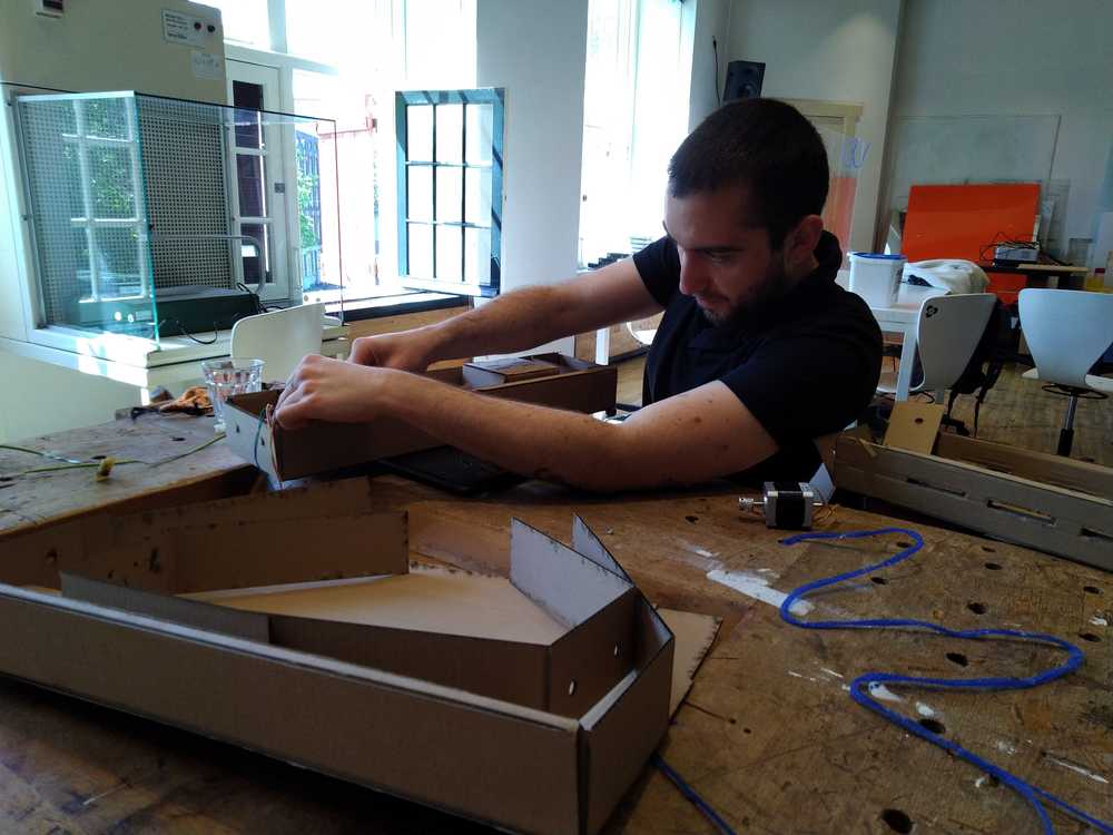
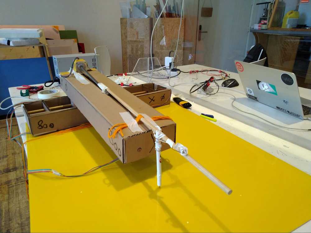
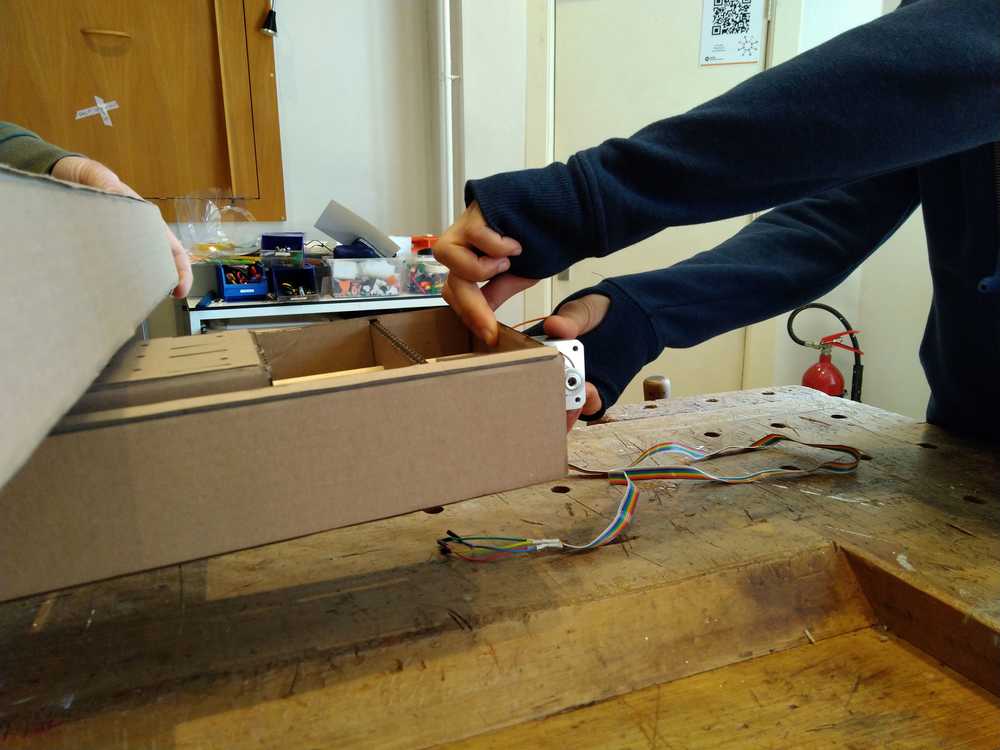
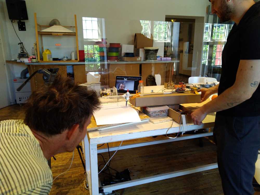
First assembly
But first we assembled the machine in a very simple way using wool and sticky tape to see how (if) it would work.
Hyejin ran the code and one arm worked but the other did not. We tried another stepper motor on the same Arduino pins, that worked, so it was not the Arduino. Nevertheless, when we moved the non-working arm to other pins, the second arm worked too.
 We added a third motor on the top of the arm that must lift the pen off the paper. It flips the pen to the side. At the front a pen is connected with tape.
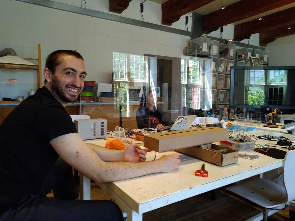
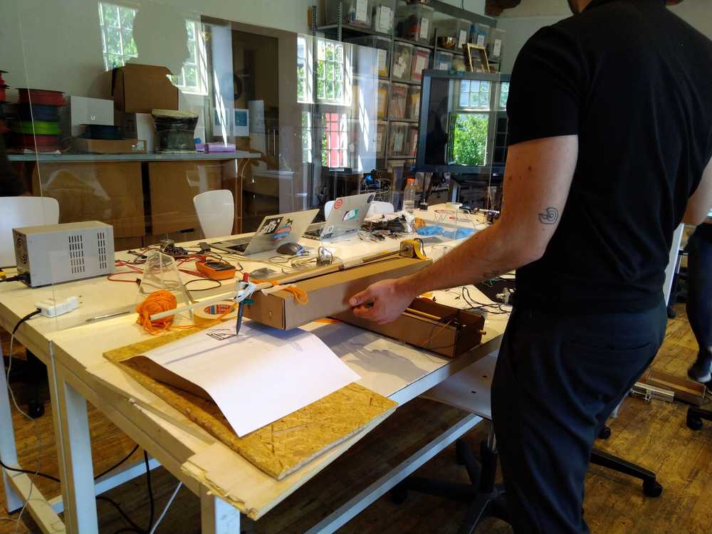
Hyejin is steering the machine.
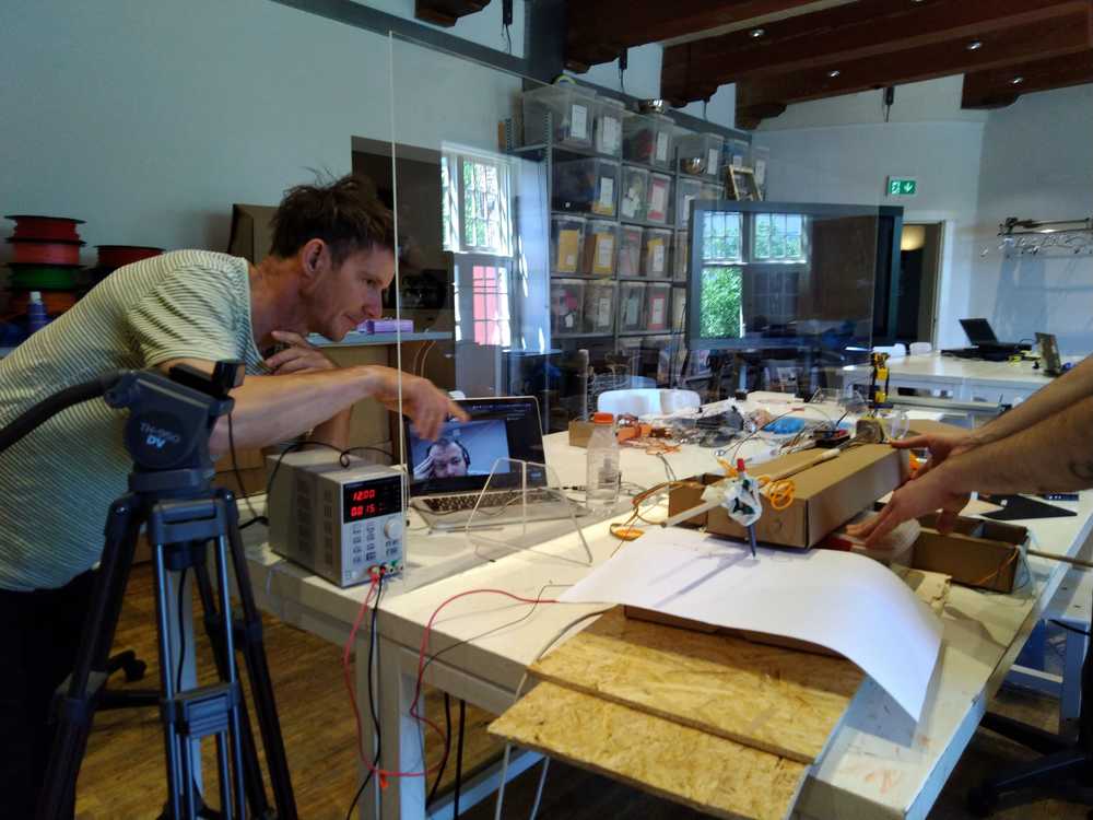 Florent joins the first demo.
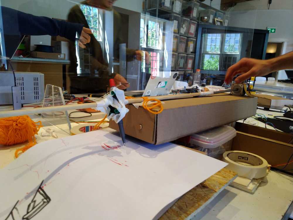
Baby’s first drawing.
Building a supporting bridge
We had thought a lot about making the supporting bridge. We considered several fancy designs. But by the time we came to making the bridge, time was running out. So Hyejin and Tessel did a really quick job. We decided to make four boxes with holes in the side. A stick would be run through the holes. The arm can then lean on the supporting stick. These bridge boxes would be placed on either side of the arm.
Hyejin made a design in Fusion360 really fast. It consisted of three parts. Two standing faces without holes and two with holes for the stick. Bottom and top of the box are a single square. We decided not to use press fit. Time was running out! Instead we would use the glue gun Harm had found earlier in the day and was happily glueing anything that was lying around loose.
We laser cutted the parts and Hyejin, Harm and Tessel glued them together. It all was super sturdy. Or at least sturdy enough. But then minutes before the Lab was closing Harm sent the arm too far and it pulled the bridge down with it.
We have only tomorrow morning to fix everything. But we will make it :).
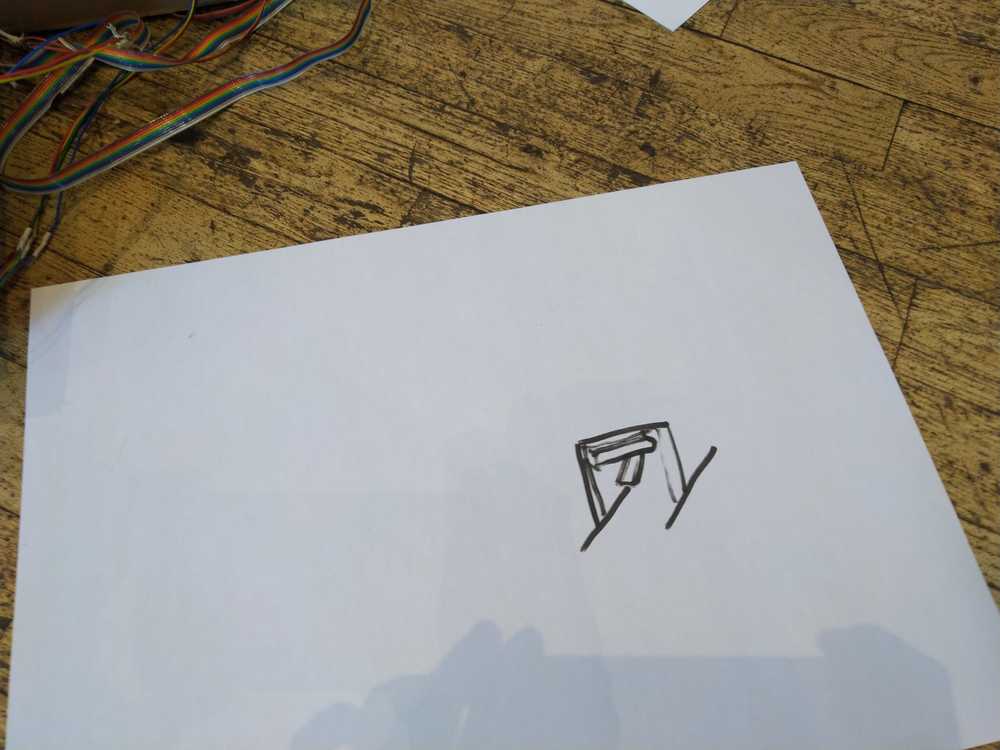
Live demo
Here are two live demo video’s of the FabConnector in action. Drawing a cat from France to the Netherlands and Drawing a robot 400km away.
Making a video
I want to make a 1-minute video for the presentation of the project. I had come up with some animated titles I wanted to use. First I tried OpenShot. To use animated titles it calls on Blender. I like that, open source programs working together. But when I clicked animated titles in OpenShot it wanted to know the path to Blender.
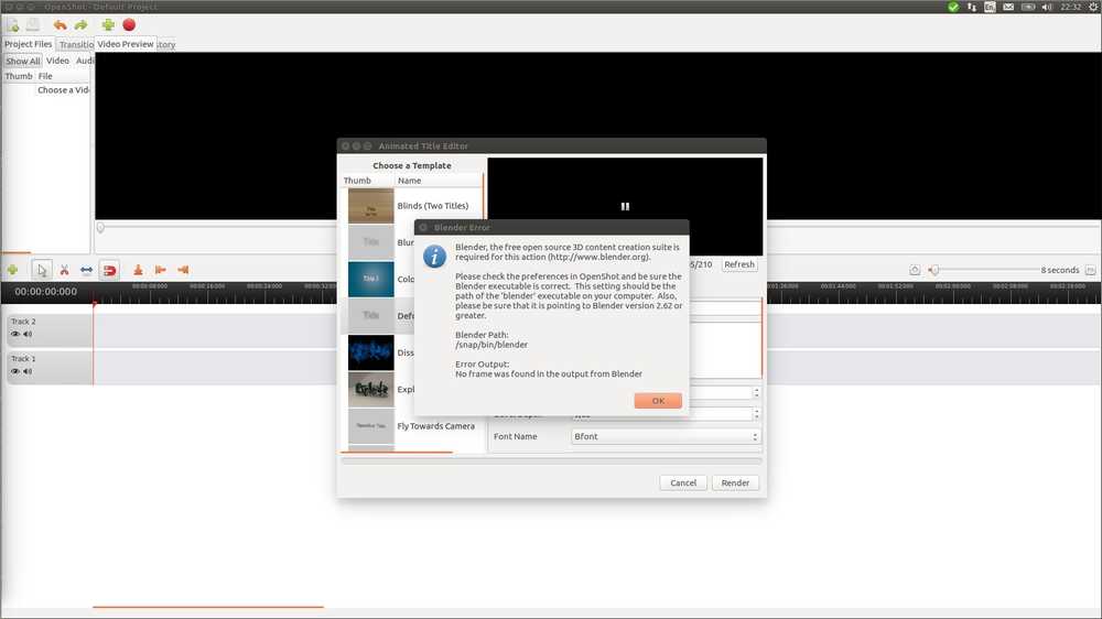
So on askubuntu I found that which blender prints the path to blender. And blender --version will tell you its version. So I did, changed the path, but openshot kept throwing up this error. So I abandoned Openshot
I’ve used Final Cut Pro a lot in the past. So I opened an old computer that still had it installed. But I suspected FCP won’t import mp4 video’s. I remembered it did not like videos from smartphones way back when. And indeed it FCP did not recognize the video format. This is an ancient FCP version, things may have improved in the meantime.
I considered making the titles in FCP exporting them and edit them onto video in Openshot. But that might give problems with transparancy. That is, having the titles overlaid on the video. Plus, when I looked at it, I realized FCP title program is not all that fancy.
On to the next open source video editing program. Rutger had recommended Kdenlive. The interface is a bit different than usual. For instance you don’t import a file under the File but under the project dropdown menu. When I found how to start making a title project > open title clip there was a button animated title. Here it seemed I was able to do what I wanted to do. So I decided to go with Kdenlive.
But the program is buggy. It has crashed multiple times already. Twice now it has disabled my mouse. System wide.
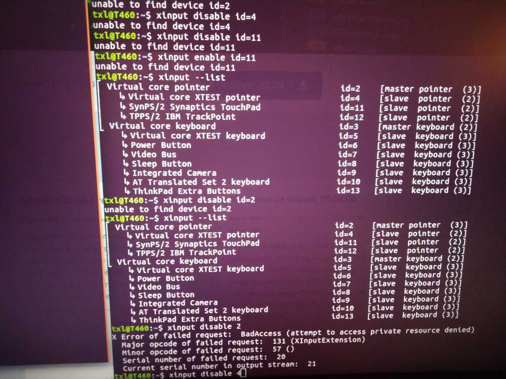
So off to the forums it was. First I searched for Kdenlive mouse/cursor diabled but that was too narrow a search. So I just looked for how to disable and enable the mouse on Ubuntu.
I found an answer: xinput --list will list keyboard an mouse devices. Then xinput disable X where X is the number after the id= entry. Afterwards you can enable everthing with xinput enable X. But when I run this command I get an error: attempt to access private resource denied. Sudo does not solve it.
I wanted to make a screenshot but ImageMagick won’t work without an enabled mouse.
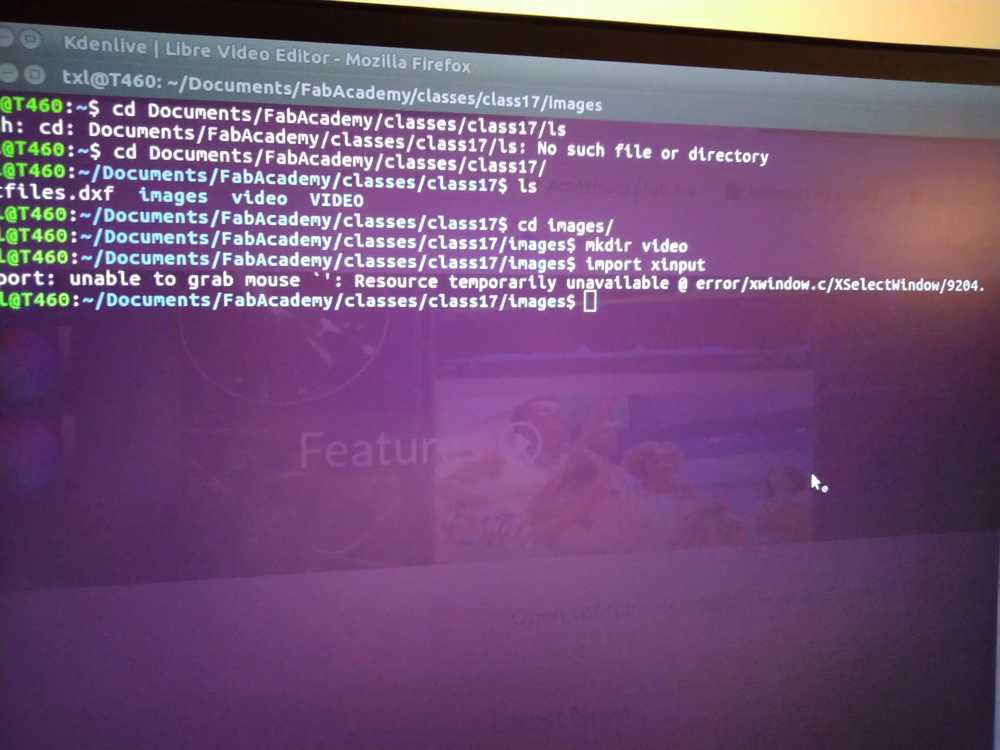
So here is a photo of my screen rather then a screenshot.
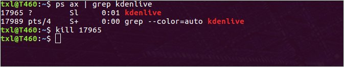
What worked in the end is ps ax | grep kdenlive this gives the process id (pid) of the kdenlive program. Then use the pid to kill the program with kill [pid number]. Then Kdenlive shut down and I had my mouse back.
Henceforth I am running Kdenlive in the terminal. That may be telling me what is going on and hopefully will make it easier to kill it if necessary.
I also remembered I did not just install kdenlive with sudo apt-get install. Instead I installed the latest version in the terminal:
sudo apt-add-repository ppa:kdenlive/kdenlive-stable && sudo apt-get update and then did apt-get install kdenlive.
Maybe that packages is not stable so I uninstalled with: sudo apt-get remove kdenlive and than did sudo apt-get autoremove to remove all the associated packages. Did sudo apt-get update and sudo apt-get upgrade. Then reinstalled by sudo apt-get kdenlive.
That did not help. Kden forum] advised to install missing package libeigen3-dev
And another package: as per the forum
apt-get install libavcodec-ffmpeg-extra56
Then from the kden page I installed the app-image. Download it, set permissions to allow executing as file program and double click on the app-image. An app-image is a stand-alone version of a program. Rather than the usual Linux way of installing different packages and placing them on different locations on the computer, the app-images contains everything in one place. This does mean it will not update or upgrade. You need to reinstall it if you want a newer version.
This app-image versus apt-get may also be the reason Openshot and Blender aren’t working together. Blender is installed with SNAP, the Ubuntu version of app-image, and Openshot through good-old apt-get.
After installing Kdenlive via the app-image it worked like a charm. It took a short time familiarizing with the fast keys and such things. I quickly went through this tutorial that explains the basics about Kdenlive’s animated titles. And pretty soon I could work with it as fast as with other editing programs I’ve used. It’s nice that program UI designers more or less sticks to the same interface.
Two things took me some time to find:
The Properties Pane is necessary for making transitions and effects. It took me some time to open it. In the end I found out The Properties pane has been renamed to Effect/composite stack. Select under view.
The other thing was to get the timeline to render the footage. That turned out to be Shift return. Make sure the blue ribbon at the top of the timeline is covering the area you wish to render.
What I learned
It is so much fun to make something together! It was really nice to collaborate on making something. One thing I learned that stands out is the project management strategies: spiral design, time supply and triage. Spiral design means you work in small spirals. Each time bringing the project to a complete finish from design to working prototype. We applied this pretty good. Working for instance first with the cardboard casing and then moving on to acrylic casing. This helped to become not completely stressed about having to make a machine in one week. Because we did have a new spiral of a working prototype almost every day.
Another important one was triage. This we applied on the end stops. We thought that this would be an easy feature to implement but it turned out to actually be quite hard. This also showed when we searched the internet for a solution. There was a lot of talk on the forus about adding end stops, so appearantly it is a difficult thing to do for many people. After having invested a couple of hours in it we decided to abandon this task. That is actually not easy. You’re inclined to set your teeth in it and stubbornly continue. But it was such a good decision to let go and spend our time on more critical tasks.
The experience of time supply was also a good one. Because we knew we had to keep moving, keep designing we did not waste much time. We made decisions quickly for instance rather than loose a lot of time on bikeshedding. Especially on the final day time supply really became fun. In the beginning you take time to make good, beautiful solutions. In the end you start to take shortcuts and get in the just-get-it-done mode. It was great to see how much we suddenly accomplished in a short time.
Machine week really brought the project management strategies explained to us in week01 home to me.
What could have gone better
I really like networking and electronics. But Harm Hyejin and Florent are much better at it then I am. Therefore on the first day I thought I would leave that part of the project to them. But on the third day I just went to work on the networking part anyway and I really enjoyed it and also learned a lot from working with Harm and Florent. So for next time I hope I will feel more confident to just join the part of the project I like.
Explanation on how this page works
For week17 the assignment was to work as a group to make a machine. The requirements for the documentation are two-fold: we needed to make one group page on which everything is documented in one place. We also needed to make a individual page on which we have to document what we we contributed individually to the group assignment.
This is my individual page. All that is documented on this page I have either contributed individually or (more likely) in collaboration with one or more other classmates. The documentation itself is either written by me individually or in collaboration with my classmate(s).
The way I did the documenatation is as follows: I documented what I did on my local computer. When I was done I pasted it on the group page. This way others could add to the documentation if that was necessary. After we we were done with collectively documenting, I copied those sections of the group documentation that I had contributed to, back to my individual page.
For the documentation review I was asked to list what I had contributed. The short answer is: Everything written on this individual page I have contributed to in one way or another. But I was asked to make more clear what my individual contributions have been. So here is the long answer in which I have made a list of all the chapters on this individual page and have added that I have contributed and with whom:
Our ideas: we all brainstormed together about what to make. I took notes during the brainstorm and documented them. Others have also added documentation to this section.
Finding the range and add end stops: Harm and I worked on the endstops together. We both contributed to the documentation.
Making a connection between France and the Netherlands: Harm, Florent and I worked on this specific part of networking (making the connection between France and the Netherlands) together. We all have contributed to the documentation. The entire job of networking has involved more than just this section. I did not take part in that. That is why I have not added it to my individual page.
G-Code TX/RX: Harm, Florent and I worked on this together. We all contributed to the documentation.
Cardboard casing: Nathan and I worked in the cardboard casing together. Heyjin contributed too but she also worked on the motors that day. As I say in this chapter: “Meanwhile Hyejin and Harm are figuring out the servo motor/stepper motor problem.” Nathan and I contributed to the documentation on the cardboard casing.
Supporting structure: Hyejin, Harm and I (and maybe Nathan too, I am not entirely sure anymore) discussed how to build the supporting structure. I took the photo’s displayed on this page and documented the outcomes of the discussion. This section also shows the first time we got the pen to move. All of us were present for that. I took the video.
First Assembly: All of us were present for this part, including Florent who joined remotely as you can see in the picture. I documented this part and took the photo’s. That is why I am not in any of them.
Building a supporting bridge: Hyejin, Harm and I worked on this. From the looks of it I think I did the documentation but I am not entirely sure anymore as a lot of things happened that day.
Making a video: I made the 1-minute video and wrote the documentation on it.