Waag Fablab: Hyejin Ahn
Waag Fablab: Harm van Vugt
Waag Fablab: Nathan Harris
Waag Fablab: Tessel Renzenbrink
Building the FabConnector
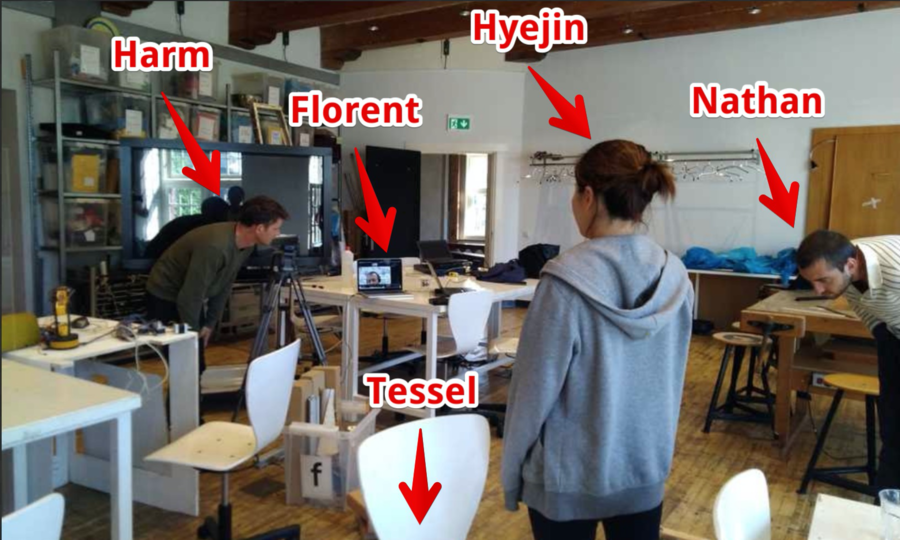
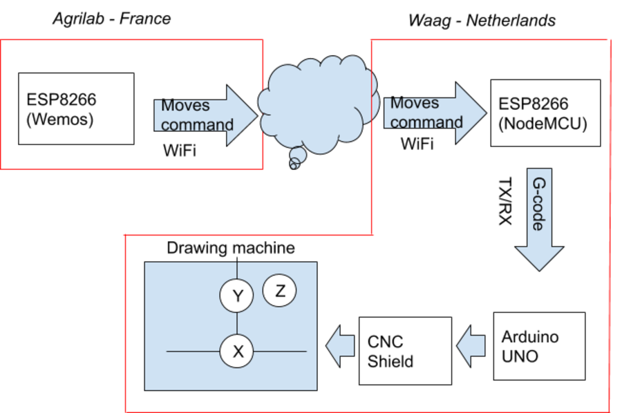
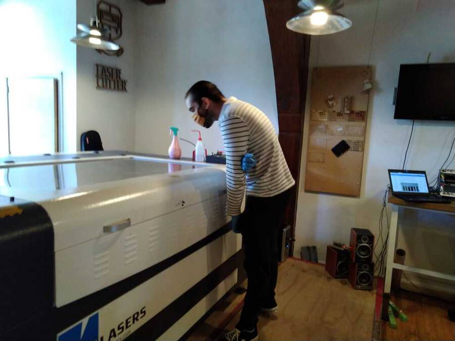
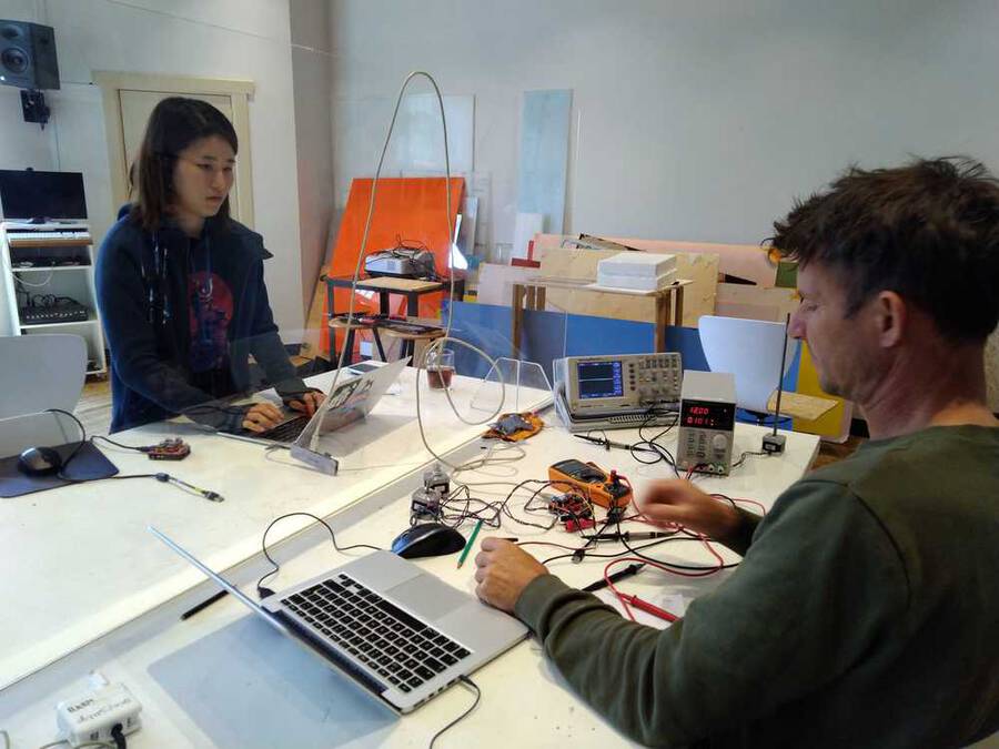
Fusion 3d file remote controll - Agrilab Fusion 3d file - drawing machine - Waag Library for running websockets on Arduino Wifi and websockets code - Waag Simple client serial communication test Wifi and Azure (no websockets) - Waag Text communication TX/RX to stepper shield- Waag live Drawing on a website using the Oled touch - Agrilab Websocket NodeJS server - Agrilab For the group assignment we are collaborating regionally. FabLab AgriLab in France and FabLab Waag in Amsterdam have joined forces to create a machine together. This is the setup for the collaboration.
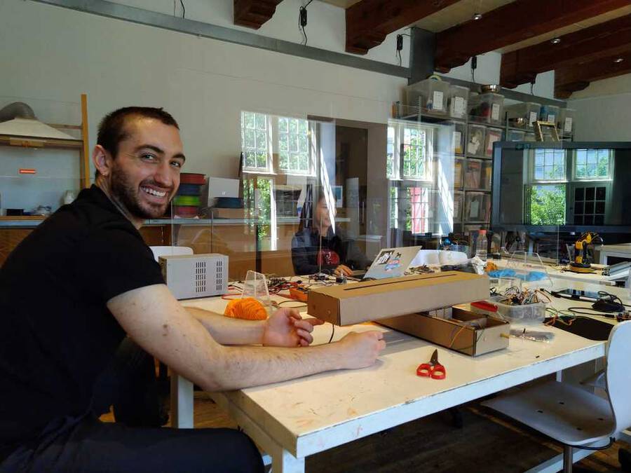
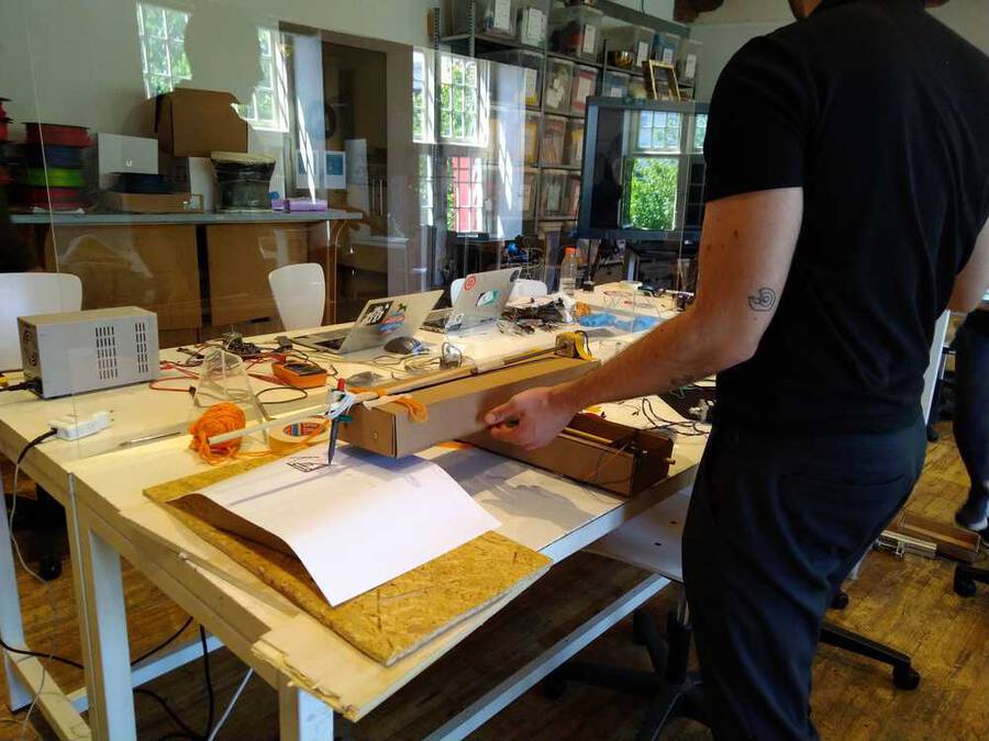
Image 1: Picture taken in the Waag. Florent from AgriLab joins via Jitsi.
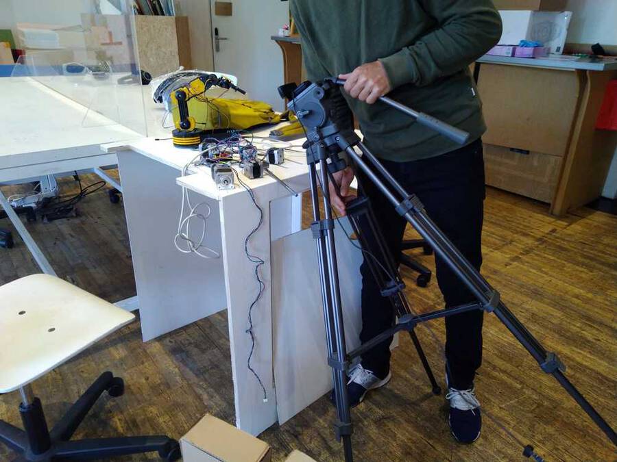
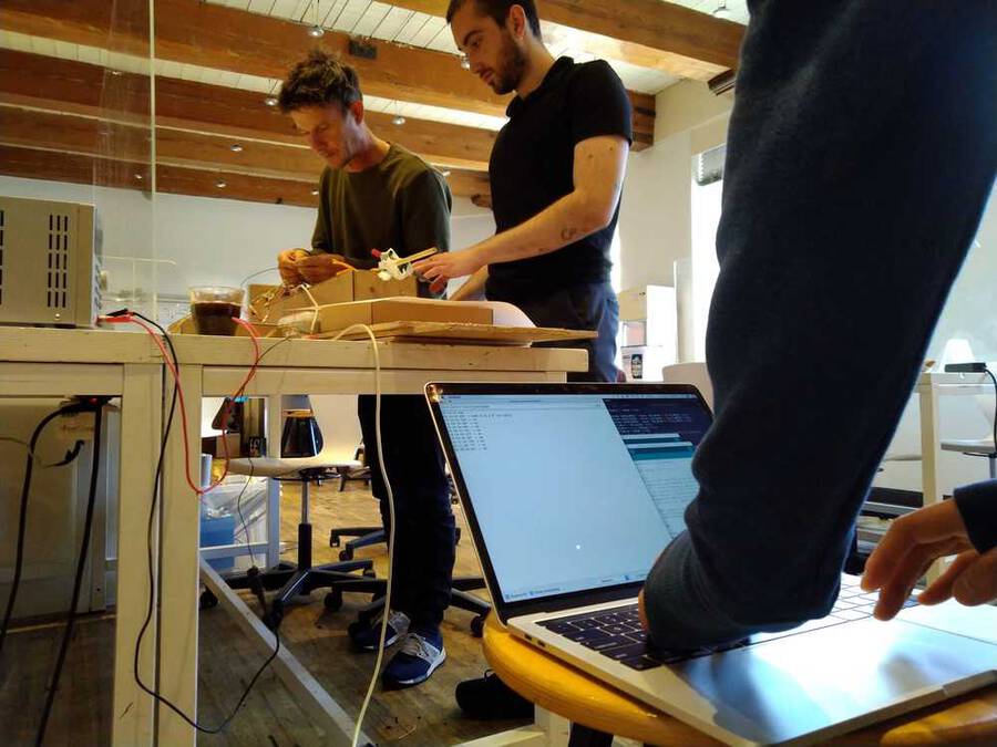
Image 2: Showing the goods. So many stepper motors!
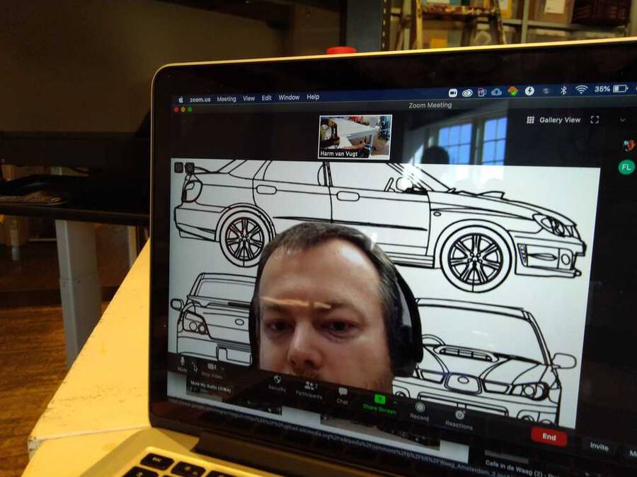
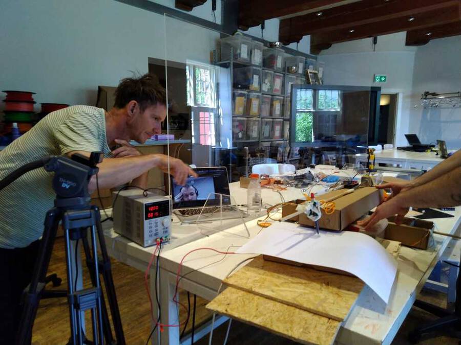
Image 3. Florent is eying the stepper motors critically. - design a Machine that includes mechanism+actuation+automation - build the mechanical parts and operate it manually - document the group project and your individual contribution - actuate and automate your Machine - document the group project and your individual contribution
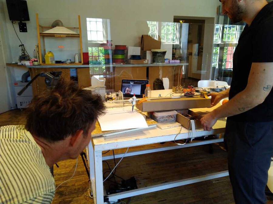
What it does
Image 4
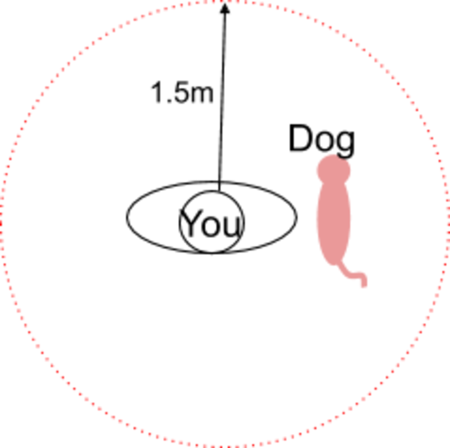
Image 5 Keep the distance
Must be rigid enough. Wood? (Composite?)
Image 6: pink dog
A pen or pencil is attached to two arms. The arms are moved over X and Y axes by stepper motors. Since our group is geographically separated our project must of course include remote operation using networking. The first iteration of the machine will consist of drawing with pen aon paper. Second iteration, replace paper with sand. Third iteration: a way to flatten the sand for a new picture automatically.
Spiral development
Mechanism for X/Y/Z Stable frame to hold it all together. Control the stepper motors: Arduino with a stepper shield. Find a way to lift the pen up and down. Connect Arduino to ESP32 or Node MCU. Nice packaging or casing.
Florent commented that if we use G-Code the machine needs to know its origin. That makes it more difficult. Just sending commands is easier.
Possible names for the project
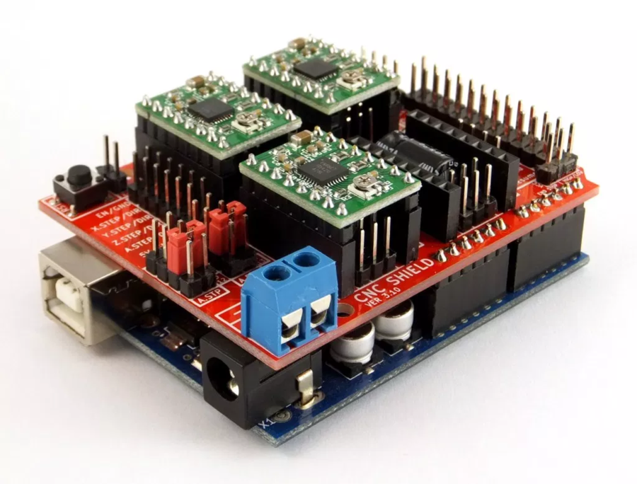
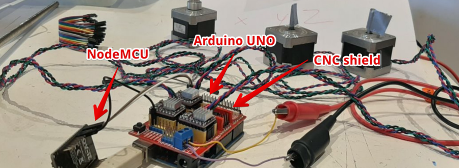
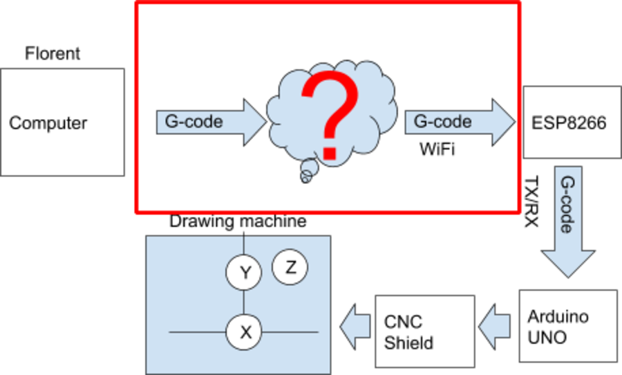
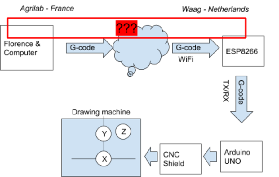
Here is an overview of the electronics and networking part of the system: Image 7: Overview of the system Henk gave us an Arduino Uno with a CNC shield and stepper motors. image 8: shield
I tried to get it running and looked in Henk's documentation Steps: 1. Connect the steppers to the CNC shield 2. Download the arduino CNC stepper Library for the shield
Sending Gcode https://reprap.org/wiki/G-code
Example Gcode: G1 X50 Y25 Z22.4 F3000 G1 X200 Y1 Z200 F8000 G1 X0 Y100 Z0 F8000 G1 is the starting of the line X, Y, Z are the axis (stepper motors) F3000 is the speed (where 3000 is the value)
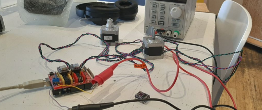
Setup for Servo motor test:
Image 9 the setup
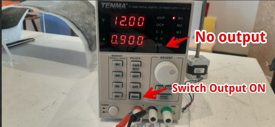
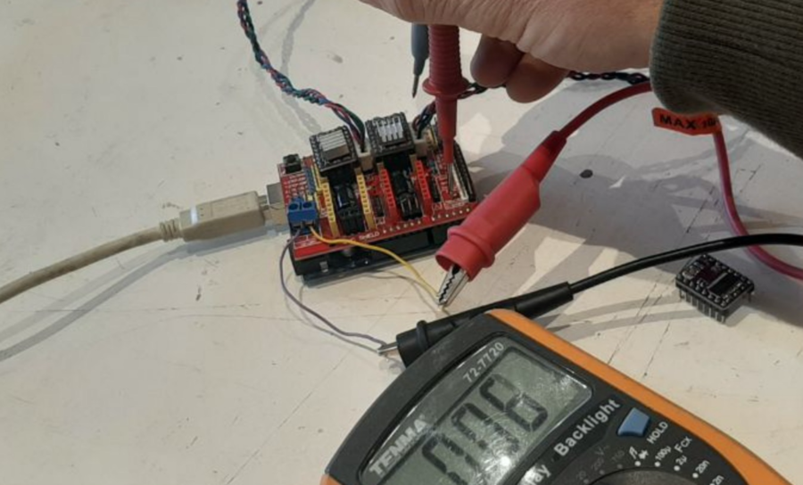
Mistake 1: The servo’s did not move. It used a multimeter to conclude the Power supply was not activated.
Image 10
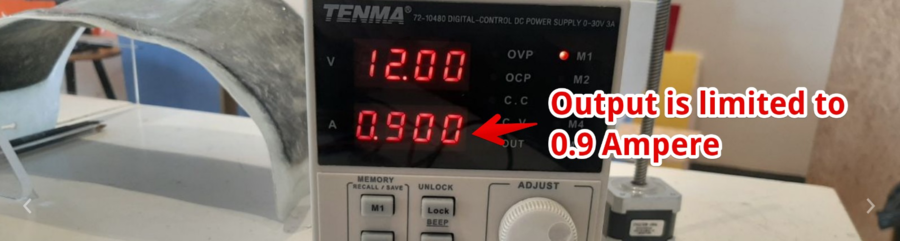
Mistake 2: Not enough power
I noticed the voltage dropped. I could see it on the Power supply.
I changed the Amperage to 2.000A. And the motors turned!
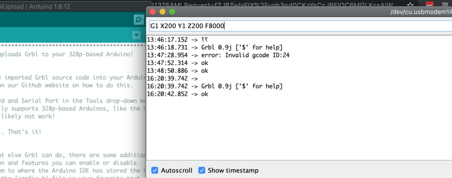
I now can enter Gcode in the serial monitor and turn it.
Hero shot
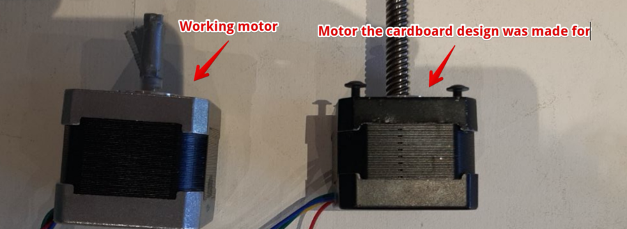
At the same time Nathan and Tessel where working on the casing, they designed it around different stepper motors:
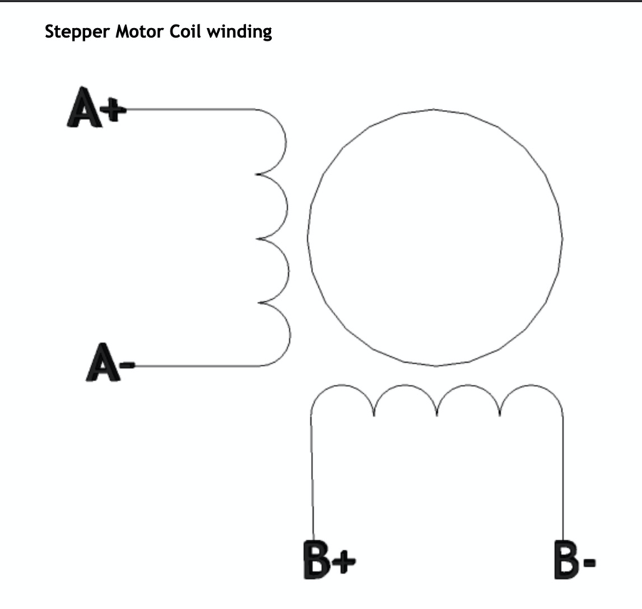
But the black Stepper motors have different wiring.
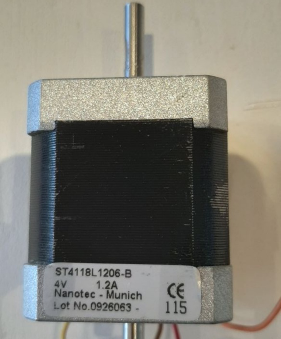
I found this stepper on this page
Image 15
But the ‘black’ stepper motors we have designed for, don’t have any type written on them.
Image 16
In this http://hobbycncaustralia.com/Instructions/iI9wirestepper.htm website we found steppers with the same wiring.
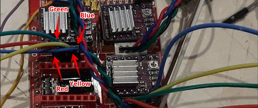
The connections with the Red, Green, Blue and Yellow wires:
Image 17
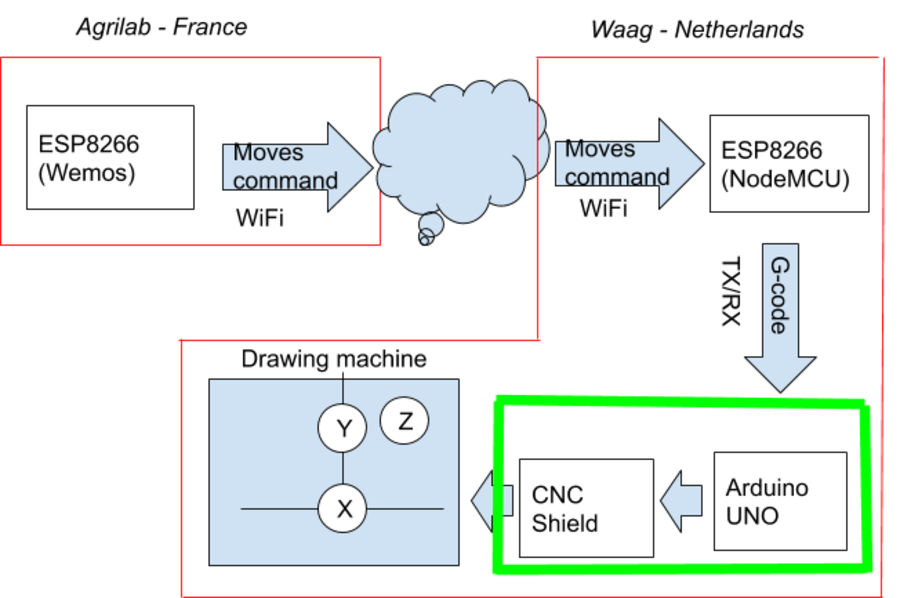
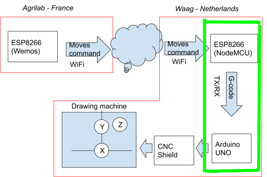
Image 18: The section in the diagram that is being documented is marked in green. The section in the diagram we
Day 1 : we have to understand how to work the CNC shield and Arduino GRBL code. After testing and searches, we found we can send Gcode via serial. First we tried with Arduino IDE, all ok. The G-code commands look like : G1 X2.0 Y2.0 F3000 G1 X20 Y20 F3000
To move to a position over the X and Y axes and F determining the speed value.
We want to drive the machine over the internet, so we add a board with wifi. We started with a ESP8266 (NodeMCU).
Working remotely is difficult because we don't have exactly the same parts on each side. At the Waag, there is the NodeMCU board, at AgriLab only Wemos D1 mini pro board. I don't have a CNC shield here at AgriLab, so I have to first create a dummy Serial Slave with an Arduino UNO board on my side.
Image 19
Since the Arduino Uno with the stepper driver has no internet connection, we thought of using a ESP8266 board to connect to the internet and receive the Gcode from France. Together with Florent we looked into ways to do it. First thing to test is the I2C. This is available on the board.
But we have to change the CNC library. So we decided to use TX/RX to communicate. First, we want to use I2C. Measuring the connection on the shield they seem to be directly being routed to the UNO.
Image 20
So this could work!
The other available pins (but not in the CNC shield) are the A4 & A5 pins. But after searching if the GRBL code support I2C, it turns out it’s not the case. And making changes in this extremely complex library does not fit in the few days we have.
Now we have possible 3 solutions :
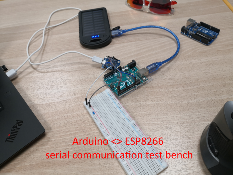
After checking possibilities, a hack is possible. At first we tested the board by sending G-code with serial monitor. So we will do the same. In the test we send it from the computer but for the machine we will do it with a ESP8266.
Image 21 At first, Florent made an Arduino slave that react to serial commands:
#define LEDPIN 7
void setup() { Serial.begin(115200); while (!Serial) { ; // wait for serial port to connect. Needed for Native USB only }
pinMode(LEDPIN, OUTPUT); Serial.println("Hello I'm arduino board"); }
void loop() { if (Serial.available()) { int cmd = Serial.read();
switch (cmd) { case 'o': digitalWrite(LEDPIN, HIGH); Serial.write("ON"); break; case 'c': digitalWrite(LEDPIN, LOW); Serial.write("OFF"); } } }
Image 22
It just reacts to messages received from serial. You send o to switch the LED on, c for shutting it off. It also responds to commands.
When all work on my side, it’s time to test and debug on the other. It takes 2x time (remote is not the answer for doing things that need to be manipulated in real world ^^ )
In the Netherlands we set up the NodeMCU -> Arduino UNO -> CNC shield
Image 23
Working together via the video connection Florent and Harm tried to enter G-codes to the Node being transferred to the Uno and rotating the Servo’s. For this we connected the RX->TX and TX->RX and the ground pins of UNO and Node together. We had to change the pins, Florent was testing with a Wemos and Harm only had a NodeMCU.
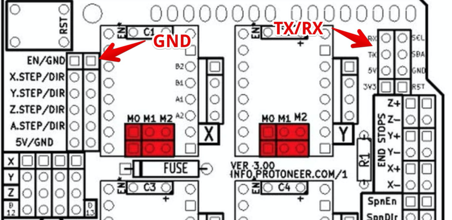
We encountered some problems: 1st problem: We could not find the GND on the Shield (since no pins are available on the UNO the shield covers this completely). We found a GND using the instructions page.
Image 24
2st problem: The UNO and Node were connected to the same laptop. Solved by using a second laptop.
This is the working code :
#include <SoftwareSerial.h>
#define TXPORT D1 #define RXPORT D2
SoftwareSerial mySerial(RXPORT, TXPORT);
void setup() { Serial.begin(115200); while (!Serial) { ; // wait for serial port to connect. Needed for Native USB only }
Serial.println("Board OK");
// set the data rate for the SoftwareSerial port mySerial.begin(115200); }
void loop() { while (mySerial.available()) Serial.write(mySerial.read()); while (Serial.available()) mySerial.write(Serial.read()); }
Now with this part working, Florent can work on the network part autonomously!
We use the ESP8266 nodeMCU. This would be a bridge for Arduino. Then we can use the ESP to steer the servo’s. If we can manage a network and I have address translation from outside to ESP, I can make direct connection by IP. Another solution is to add a rebound server that hosts a connection. And ESP will connect as a client on the server. Florent will also connect as a client. Then we don’t need to deal with firewall rules and NAT.
Next internet part.
Image 25
Florent started creating a Node 12 webapp on Microsoft Azure. After creation, I have to enable websockets
Image 25-ws
But I lost much time due to the obscure web app management from Azure. 2 days lost with error & retry of different configuration, code and so on.
I first use Socket.io, Microsoft itself put a tutorial to set up a socket.io server on azure but all code is old and now wrong. I also don’t want to use all embedded Azure stuff, I want to manage my webapp by myself, put the code like I want, no seup a full CI/CD just for a week. Dirty you think? NO just faster, we don’t have time to play. We want a working machine !
When I set up the first webapp, all seems ok, websocket is correctly activated, i finish to have a NodeJS backend working and I think, because all is up, websocket are working too.
WROOOONG! Even if I activate websocket, it never works!
When we make the first test with a chatboard, it seems to be working. But socket.io is cheating, it falls back silently to XHR polling, websocket still not working and 0 error.
Image 25-draw
So much time spent… Finally I found THE solution !!! We are on Azure, Azure is from microsoft, microsoft is creator of windows… So I create a new NodeJS webapp but this time I put a windows server behind it. I apply the same settings, I activate the websocket and nooow it’s working… What a loss of time. The first clue, I think I have to keep in mind on it at first time. When you set up a webapp, even if you choose a Linux or windows OS, Azure uses an IIS server (no apache, no nginx, IIS!!! lol)
Second round Now, I have a working NodeJS & WS backend working with socket.io. I try with a computer and it works. I have ws & wss endpoints. I can touch it with a computer. First it’s difficult to test ws (without ssl) endpoint with a vanilla browser, by example if you use this page : https://www.websocket.org/echo.html Because now, when you reach a page, it always scales up from http to https if available. And if you are on a https page, you can’t access ws endpoint due to CORS settings in browser. For that, using a plugin on chrome like Smart Websocket Client does the job :
Image 26
Ok, a computer can reach websocket, socket.io JS api works. Next step is to connect with an ESP8266. I can’t use a simple websocket connection because socket.IO adds a lot of stuff on it. I try a demo code from the websocket library, it never touches the endpoint.
Time is running… switch to direct websocket connection between the Wemos board in France and the NodeMCU board in the Netherlands.
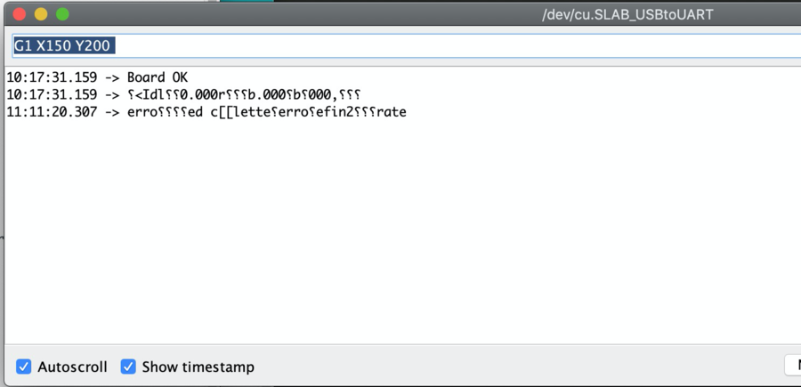
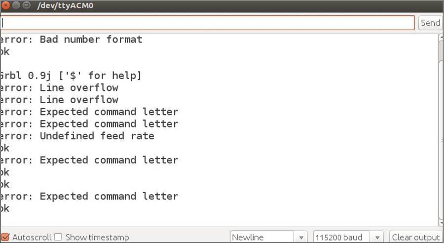
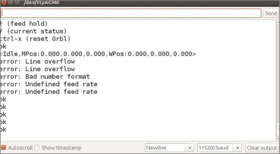
When reconnecting the NodeMCU on my computer and sending Gcode via the nodeMCU to the Shield. I got these error messages on the Serial monitor.
Image 27
Some of the error messages are strange because you get it back via TX/RX from Uno to NodeMCU. But It looks like ‘Error Defining Rate’ So I looked at the feed rate. And this is the solution:
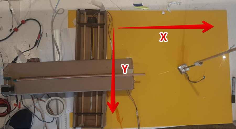
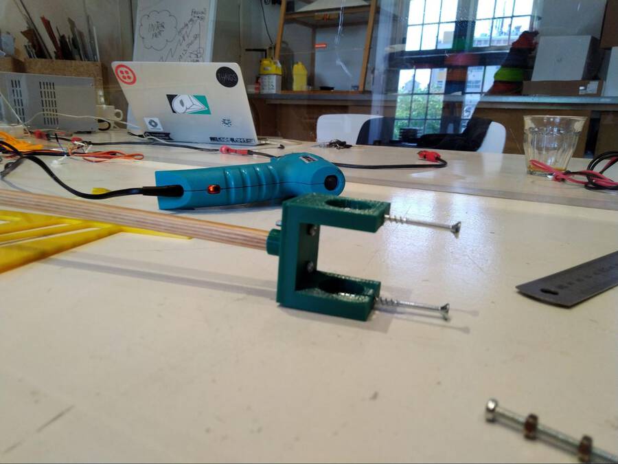
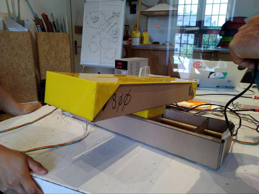
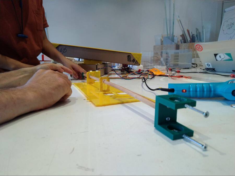
Range: We brought the X-axis very close to the stepper motor. From there we guessed it’s range to be 800. We enter G1 x800 F3000 into the serial monitor. The X- moved to close to the end. There is still a little length left on the threaded rod of the X-axis. But we decide that we will place the end-point here. This allows for a little bit of leeway for things to go wrong. So we have determined the range at 40cm which translates the value 800 in G-code. We assume that the range for the Y-axis is the same.
image 28 Beginning and end points of the X and Y axes.
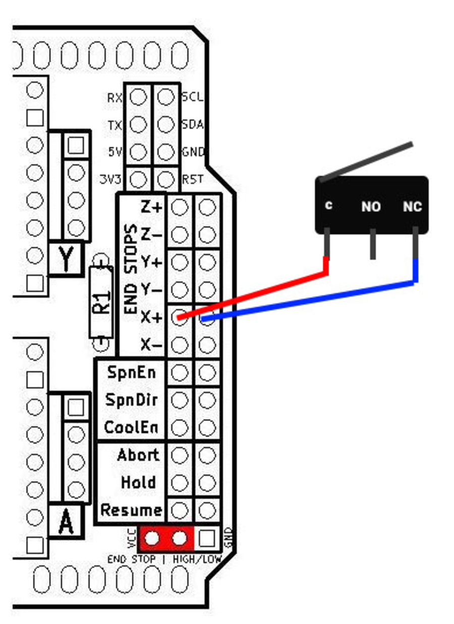
Next up we are going to make physical end points. We will add buttons on the end of the axis. There are pins on the CNC shield that are called end stops. It has six of them: Z+, Z-, X+, X+,Y+, Y-. We will connect the pins to a button. When our machine’s axis reaches its end point, it will physically push the button. This will send a signal to the CNC shield that the end stop has been reached.
First test: We connect the computer directly to the Arduino, rather than having the NodeMCU in between. This makes it easier to do tests.
Image 29
If you want to know more about this schematic you can look at this post. It shows pictures of an actual setup with Arduino and buttons. https://github.com/gnea/grbl/wiki/Wiring-Limit-Switches
The schematic shows the pinout of the end stops. We did the following and expected it to work. We connected one wire to both the pins highlighted in the picture. We then moved the X-axis. If we pulled one side of the wire off one of the pins, it simulates a button being pressed. We tested this but the X-axis did not stop. Source for this experiment is this page.
Next we looked at this video. This person connects the wires in the same way we did. But they also give GRBL commands (the library on the CNC shield. Here is an overview of all the GRBL commands. You can enter the commands through the serial monitor. The command is called `Hard Limits (Enable/Disable)`. It “requires limit switches be installed and looks for one of the limit switches to be activated which triggers "Alarm" mode. In this mode, all machine motion, the spindle and coolant are shutdown .“. The command is: `$21=0` where 0 is deactivated and 1 is activated. But this also did not work.
We then decided to abandon this quest. It is not the most important part of the machine. We can zero the exis by resetting the Arduino and keep them in mind when operating the machine. Of course it will be much better to have end stops but for spiral development more important is to get the machine to work in the first place.
So for now we are going to work on a more important spiral: testing if Florent can send g-code from France to steer the machine. Once we know that that is working we can go back to the end point spiral.
Image 30
We try to get data from France to the CNC machine. For this we have to open a port at the Amsterdam side. We first need to find the IP address of the NodeMCU. 1. We uploaded a simple Wifi code to get the Node on the wifi network. 2. Got feedback from the NodeMCU WiFi connected 13:49:19.091 -> IP address: 13:49:19.091 -> 10.1.3.240
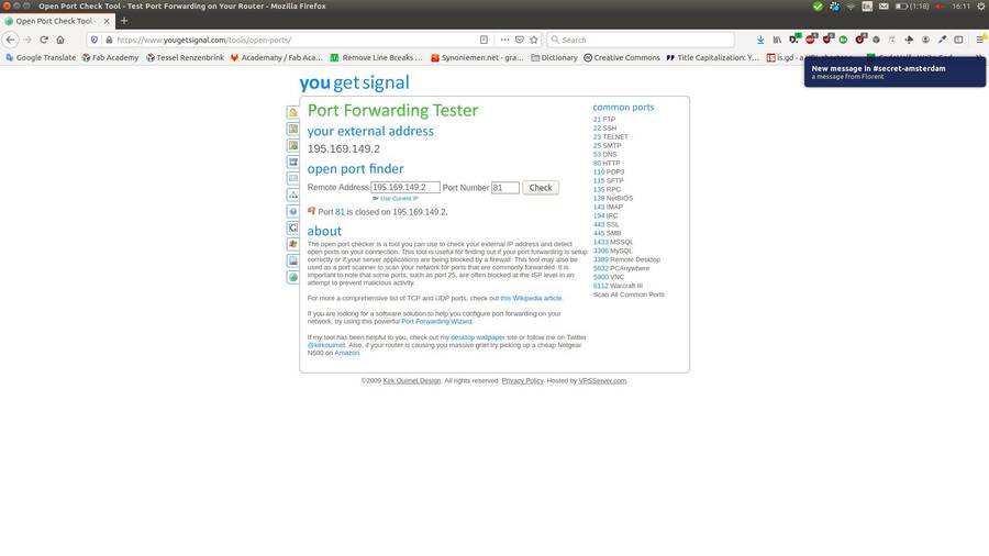
We then looked up the IP address of the Waag. Because Florent needs it to find us over the internet. You can find out your IP address via this website: https://www.whatismyip.com/. We used that IP address and asked Henk to open a port. He opened port 81 So Henk is forwarding 195.169.149.2 (our Waag connection) port 81 to NodeMCU (10.1.3.240) on port 80
We used this online tool to check if the socket is open. It scans if the port is open. But Henk told us not to use a port scanner. It triggers the firewall of the Waag network and closes the port. Henk told us that after some trial and error. Oops!
Image 31
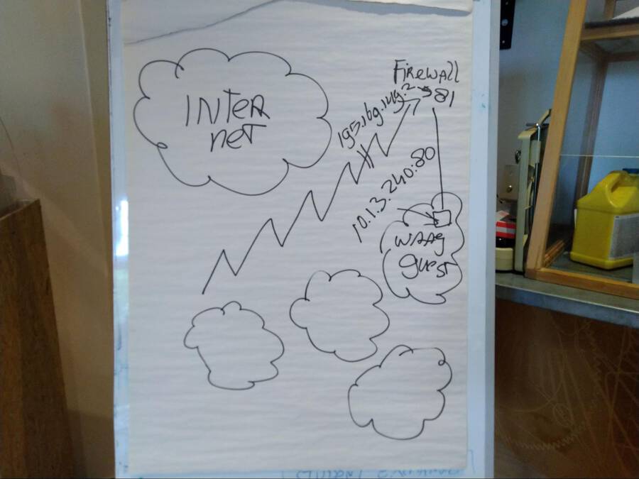
Henk explained how the networking setup works:
Image 32
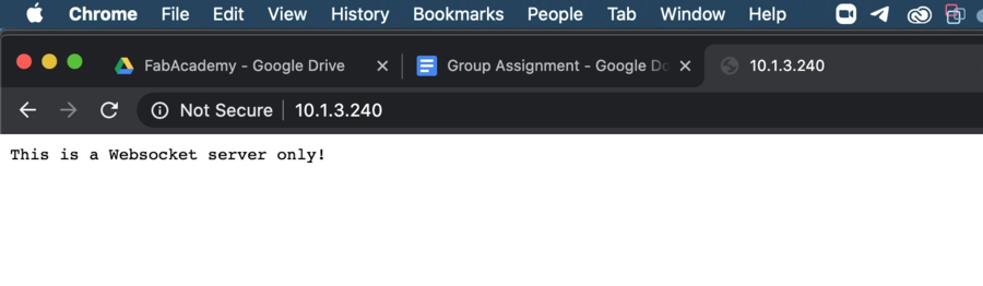
Outside is the global internet The little clouds are the Waag network. It has multiple subnets. Florent contacts us via the 195.xxxx IP-adress. Henk made a little hole in the firewall for Florent to enter through. And he reaches port 81. (We don’t use port 80 because port 80 is always already occupied.). This port 81 communicates to IP-address 10.13.240 on port 80. This is the IP-address of the NodeMCU. Us people on the Waag are already within the Waag network. So should we want to connect to the NodeMCU we use the 10.13.240:80 IP address should we want to address it. So we could test if the NodeMCU is visible in our own network. By entering the ip address in the address bar of a browser it worked.
At the same time we got a websocket code ready Link to code:
Image 33
Florent will find us via the IP-address and will attempt to connect to the opened port.
Florent will talk to port 81 coming from the outside wide internet. But internally we use port 80. So port 81 receives data from Florent and port 81 will talk to our internal port 80.
Florent sent a code. We did some remote debugging. And got a final code working with websockets:
We were trying to send g-code over the NodeMCU. This did not work at first. One problem is that the response from the NodeMCU in the serial monitor is gibberish. Then we connected one computer to the Arduino Shield and the other to the NodeMCU. This way the Arduino-connected computer received input from the shield that was actually readable.
Image 34
Image 35
We could now read the error messages and could see there is a line overflow. After giving one command to the machine, there was immediately another. This led to line overflow. We added a delay after each line and now it works.
Code
while (mySerial.available()) Serial.write(mySerial.read()); mySerial.write("G1 F3000\n"); delay(500); while (mySerial.available()) Serial.write(mySerial.read()); mySerial.write("G1 X40 Y40\n"); delay(3000); while (mySerial.available()) Serial.write(mySerial.read()); delay(3000); mySerial.write("G1 X10 Y10\n"); while (mySerial.available()) Serial.write(mySerial.read()); delay(3000);
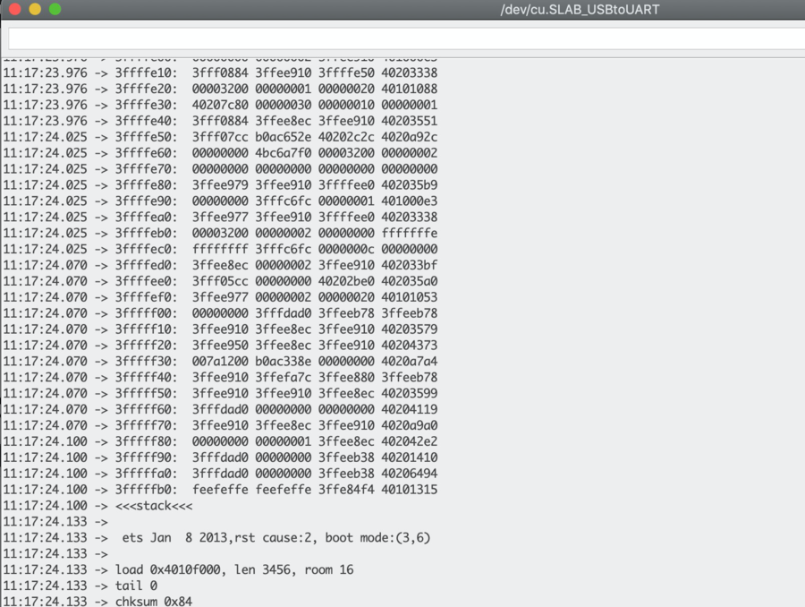
Azure round 3: Overnight Florent worked on a solution to be able to connect both sides with an UI on the French side. After changing the pins and network properties the code ran on the NodeMCU but crashed:
Image 36 We looked at the code and found the problem: Serial.printf("[%u] get Text: %s\n", payload); Was changed in Serial.printf("[Wsc] get Text: %s\n", payload);
This is the working code with the Azure solution: For Azure part, the ESP8266 (wemos) remote control remains the same, just move to another ws endpoint.
On Azure side, it’s now a rework from scratch using pure websocket with NodeJS using express & ws libraries.
The NodeMCU part is also new for websocket part because now it’s also a client of the Azure endpoint and does not act as a websocket anymore.
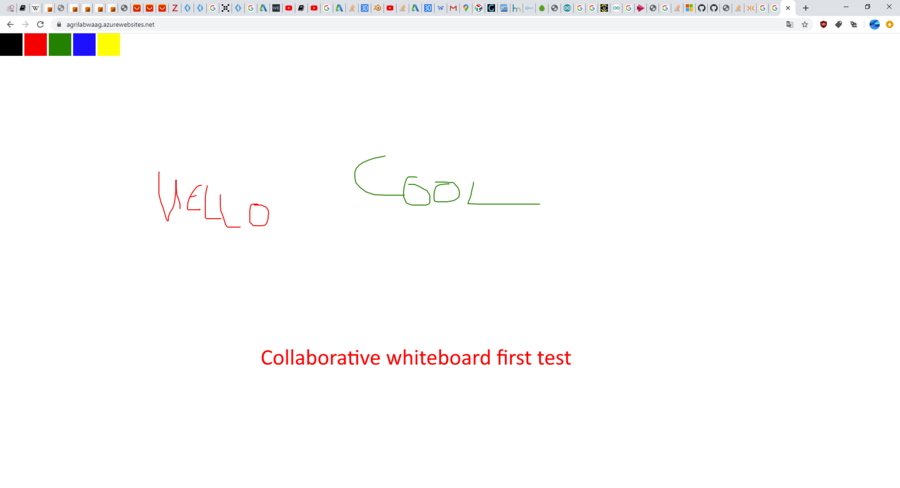
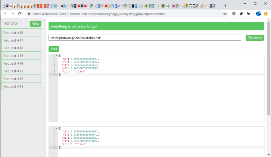
At the same time, whiteboard code was changed to also use native websocket instead of socket.io. It’s now lighter & faster! The color selection is removed, because there’s only one pen on the drawer.
Now when we draw on whiteboard, it sends json frame on websocket like this : { "x0": 0.5666666666666667, "y0": 0.2435500515995872, "x1": 0.5666666666666667, "y1": 0.2435500515995872, "color": "black" }
Final goal with that, but we run out of time, is having this whiteboard connect to the nodeMCU and when we draw on the whiteboard, the drawer in Waag does the same drawing IRL.
Since we would like to get the maximum speed drawing and we use the threaded rod we should step the motors as fast as possible.
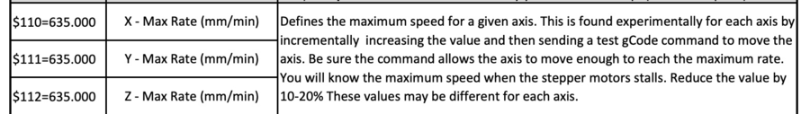
This post explains finding the maximum feed rate of a stepper motor is not easy to find. They suggest just go and test it. We found in the description of commands used in the GRBL library (driving the CNC shield) how to change the maximum Feed rate:
Image 37 Since several posts suggest the same. I decided experimenting is the best way to find the max speed.
I changed all to $110=99999999 $111=99999999 $112=99999999
G1 Z0 F99999999 G1 Z1000 F99999999
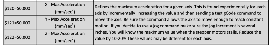
This works. But Acceleration is still a bit slow. The PDF shows Acceleration is done by:
Image 38
I changed $120 to 122 = 50.000 from $120 = 500.000
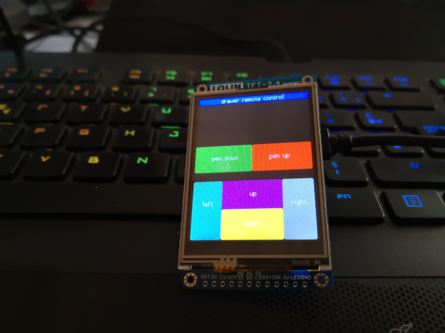
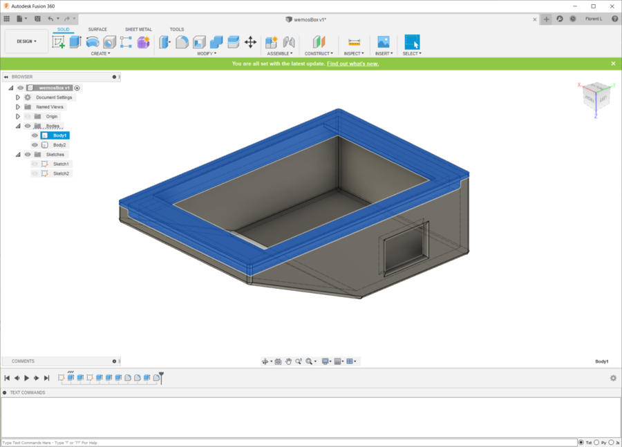
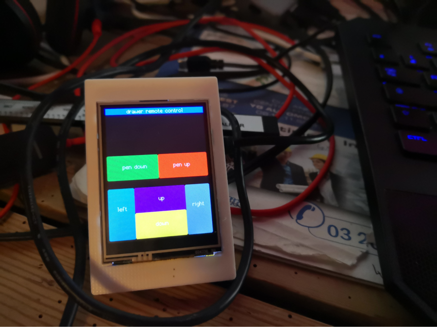
On AgriLab, I have wemos board and tft 2.4” touchscreen I design an UI for controlling the remote drawer with the touch.
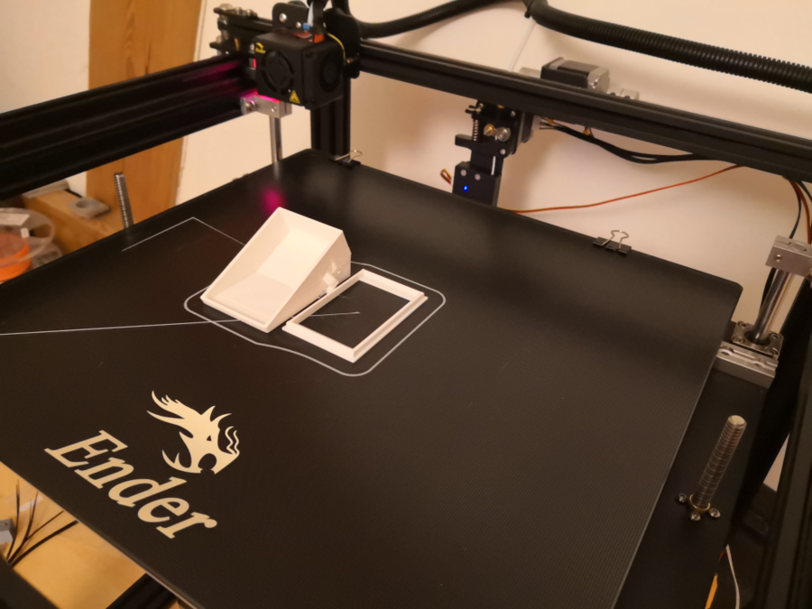
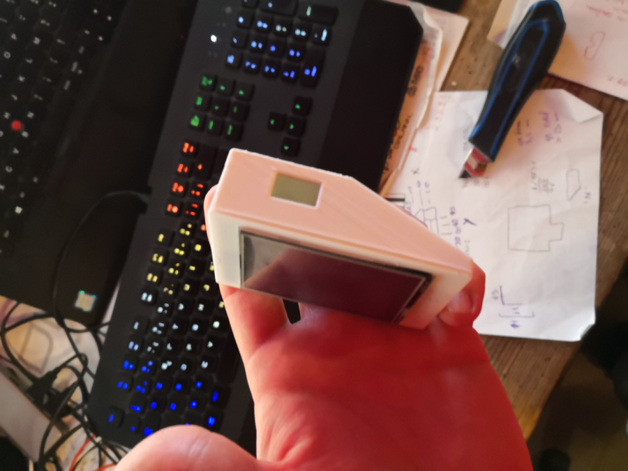
Image 39 I take measure and design a press fit case on fusion360 and print it on my 3D printer.
Image 40
Image 41
Image 42
Image 43
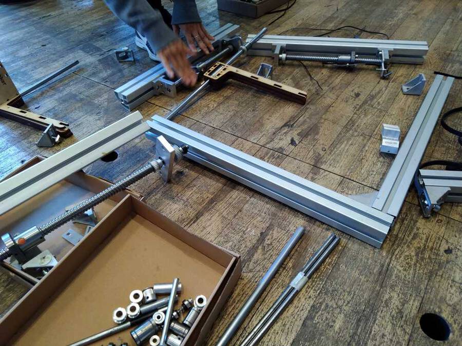
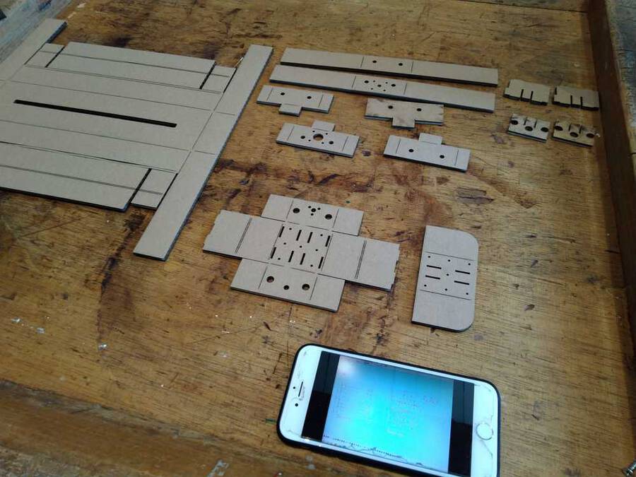
Lot’s of parts but no manual :0
Image 44
Image 45: We figured it out.
We will use these parts to make the X and Y axes. Nathan and I will create the frame to hold them. First we will create the frames to hold the two axes. After that we will move on to create the bed of the machine and a frame to hold it all together.
Image 46
One idea to steady and support the X-Y axes is a bridge or upside-down U-form. It needs to be sturdy enough to hold the axes and it needs a steady base so as not to topple over.
But first we will make the frames to contain the axes and stepper motors. We will use this example to start from.
Image 47 Source: https://mtm.cba.mit.edu/2014/2014_mmtm
This is made by Nadya Peek. She makes machines and casings that are easy to use. Even for people without much experience or huge machines at their disposal. Then on Monday during the recitation on machines she was actually one of the presenters! :) So we got to thank her for her wonderful design.
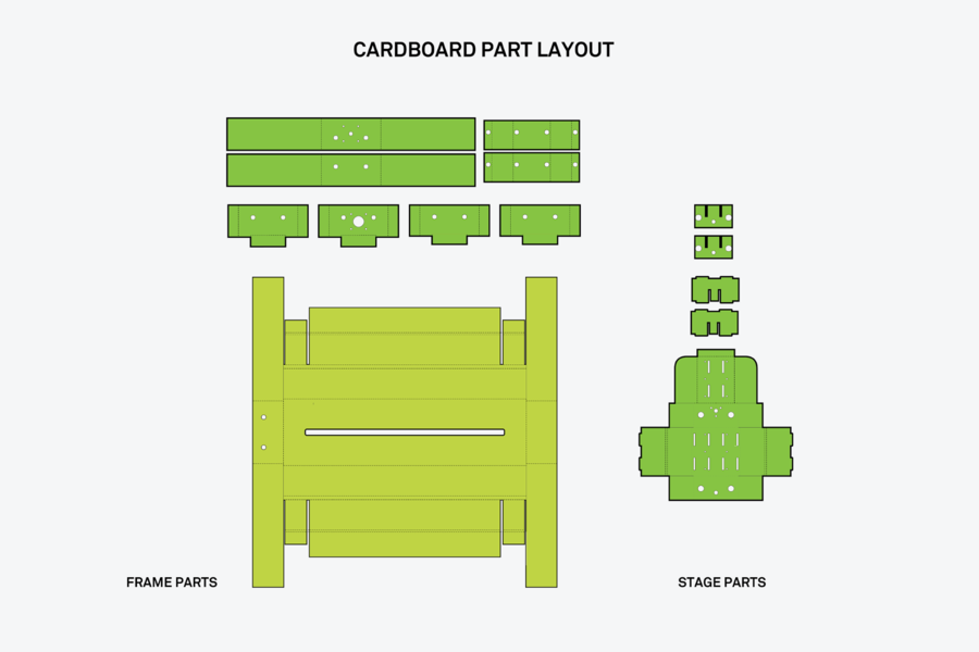
We downloaded the example file from MIT. There are different one’s available on the website so go there to choose the one that fits your work environment best.
Nathan added the file in photoshop and removed the fill-in colors that aren’t necessary.
There are two types of lines in the design. The striped lines are folding lines. The laser cutter musn’t cut them but only engrave them. The whole lines must be cut. When running the design through Illustrator and turning it into vectors, the dotted lines disappeared. So Nathan went back to photoshop and turned the striped lines into red lines. Then we found other files in which the striped and dotted lines were already made in blue and red. We ran a test run on the laser cutter. Not to waste cardboard we made the design 4 times smaller.
Image 48 For the cutting trace we set settings to power 100, speed 100. For the engraved trace: power 45, speed 100. The cutting went alright but for the dotted lines the settings were too high. The laser cut right through instead of just making a folding cut. We tried again at power 15, speed 100 and that did work. Triple cardboard: power 15, speed 100
Image 49
This is how the test came out. Laid out in the way of the source file
We then proceeded to use 2-layered cardboard to make the real size frame. But then we found a new obstacle. We wanted to fold the model together but some dimensions were a little bit off. We then realized the original is done with 1-layer cardboard. So we then used 1-layered cardboard and wanted to laser cut again. But now the laser cutter would not work. The laser would shortly blink and then stop sending laser light. Henk helped debug the machine. We then realized the power was set to 5. But the laser won’t come on at settings below power 10 to 12. So that was solved.
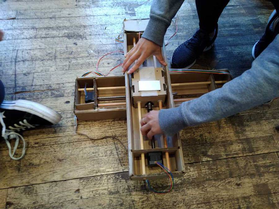
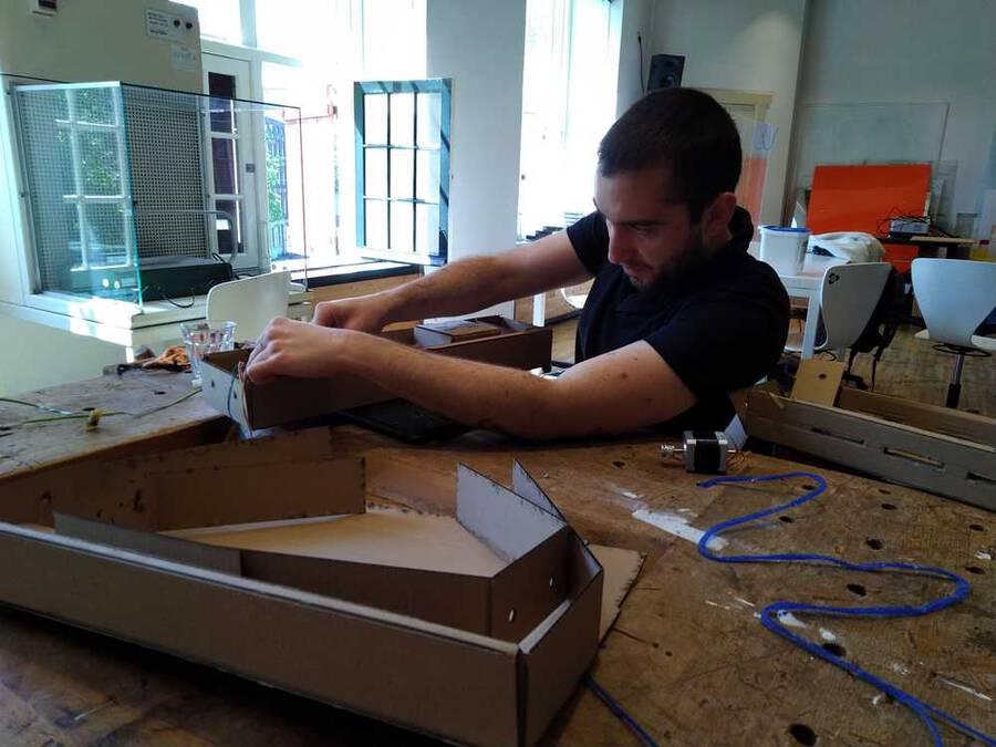
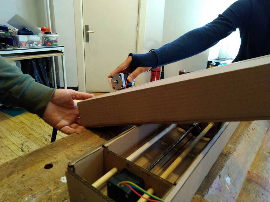
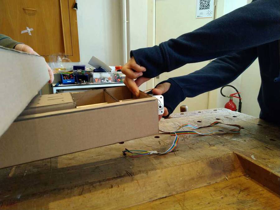
Image 50: Folding the design took some figuring out.
Image 50-fin: Finished the frame of the X and Y-axes
The X and Y axes are two stepper motors with threaded rods on them. But the Z-axis is different. It is used to put the pen up and down. The pen must be lifted up in order to have gaps between lines. Since the servo is really heavy and an overkill for just moving a pen up and down we looked into other methods of doing it. Hyejin and Harm tried to get a servo running using the stepper motor drive shield.
Image 51 We managed to rotate a servo a bit on the G-code Z-axis command. But the servo had no power and felt out of control. So we abandoned the servo plan. Instead the Z axis will also be made to move with a stepper motor.
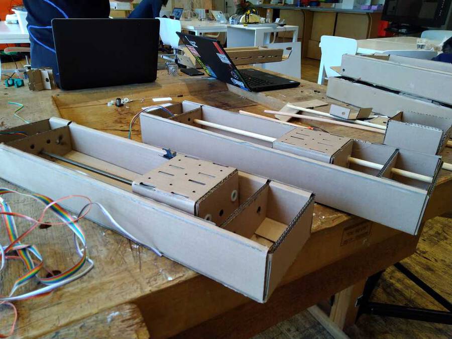
Next up is the bed of the machine and the rest of the supporting structure. The cardboard casing for the X and Y axis are strong. But when you place them on top of each other they become wobbly. The machine needs to become more sturdy
Also, now that we will use the stepper motor for the Z-axis there is extra weight. If you place a stepper motor at the end of the axis arm, it is much too heavy. It will topple over.
Image 52
Therefore the better solution is to lift the entire arms structure.
Image 53
So for the rest of the structure we have to do a couple of things: Keep in consideration the length and width the pen will move. Outside of those lines you can build stuff like the box for the lower arm.
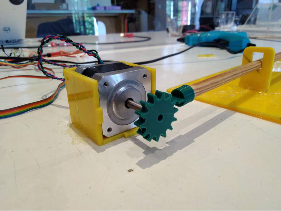
Image 55 First pen down system. Rotating the Z stepper motor
Image 56: Gear moving the pen << Hyejin
Image 57
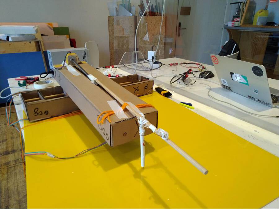
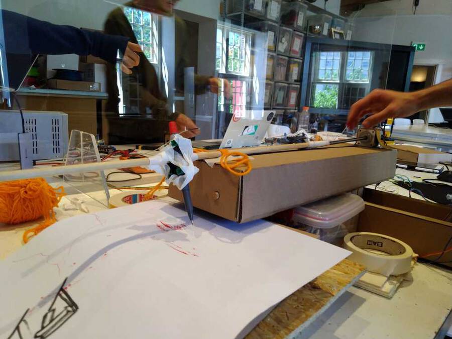
We assembled the machine in a very simple way using wool and sticky tape to see how (if) it would work.
Image 58
We added the third stepper motor on the top of the axis to lift the pen off the paper. It flips the pen to the side. At the front a pen is connected with tape.
Image 59
Image 60
Image 61
Image 62: Florent joins the first demo. The problem is in the structure, it is not rigid enough. We all have to hold it.
Video of the first drawings of the machine
image : 63 Baby’s first drawing.
For the design, we wanted to make a shell to encase the cardboard structure so that it would be sturdier and look nicer. There was a lot of scrap plexiglass laying around from Rutger’s work at the start of quarantine.
The design involved 3 main parts.
We made the entire design in a few hours over the weekend, but it took foreverrrr to fabricate. This was partly because Nathan decided to make the design press fit, and probably should have abandoned that idea and used glue much earlier. It was also largely because using the laser cutter is so much more frustrating than I remembered. Many times, the files simply would not open, or the entire computer would shut off. The laser cutter requires .ai CS2 files. I was working in fusion, so I would have to save as a dxf, open in AI, save again as a legacy format, then bring to the machine. I often had to repeat this process a few times to get a file to work. The settings I used for cutting 3mm yellow plexi were Speed: 20, Power: 100.
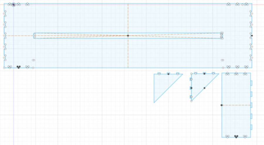
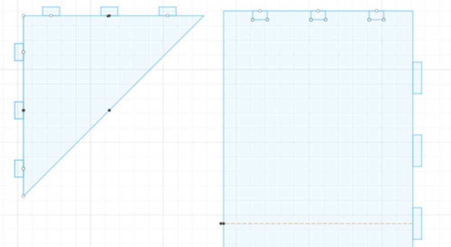
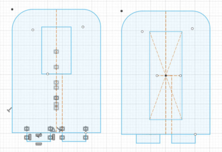
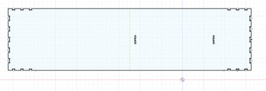
The main shell design involved a 3 part press fit kit, a large rectangular base, then a pair of triangles and a rectangle that fit together at the ends to make the end of the box.
IMAGE 64
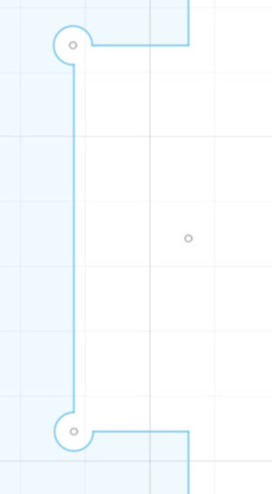
We used finger joints, and added circles to the inside corners of the joints to prevent cracking.
IMAGE 65
IMAGE 66
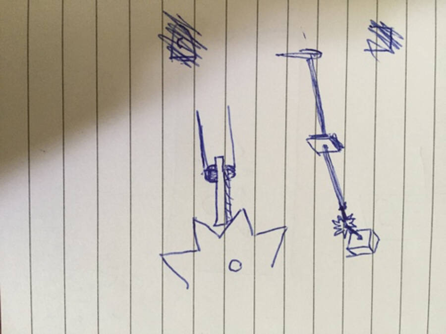
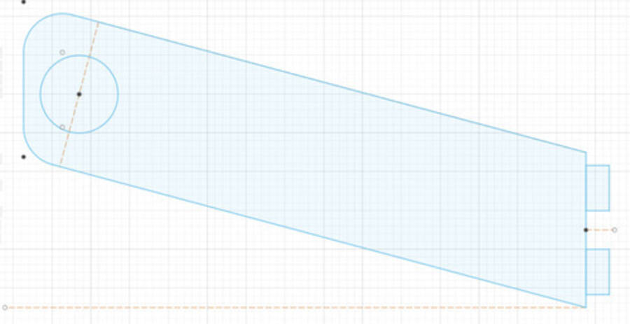
We drew this rough sketch of the Z axis support system. It involved a gear, pen holder, and fulcrum.
IMAGE 67
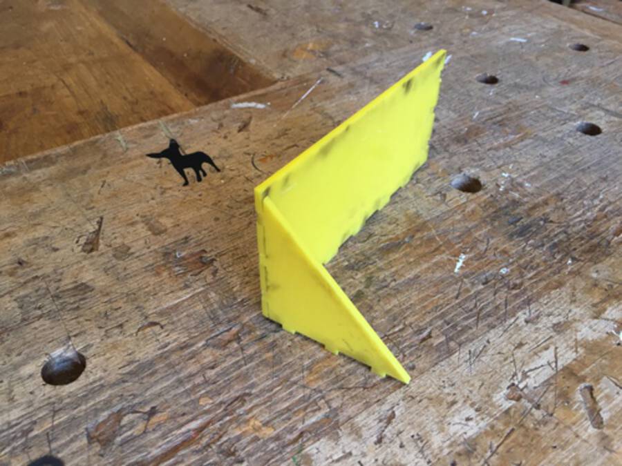
Here is a design for the fulcrum and an additional guide for the stick, with finger joints that fit into the shell on the outside of the box.
IMAGE 68
IMAGE 69
Here is an initial bridge support we made. The idea was that it would fit into a base for the drawing machine, then hold a wooden stick that the box could roll over as it moved. We did not end up using this design.
IMAGE 70
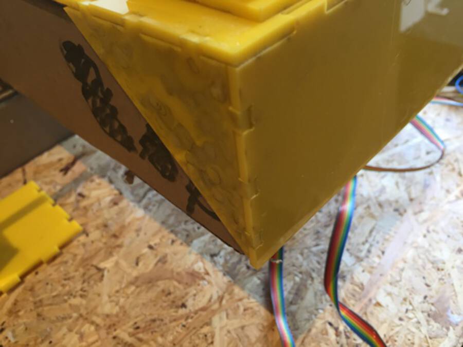
The shell joined together:
IMAGE 71
IMAGE 72
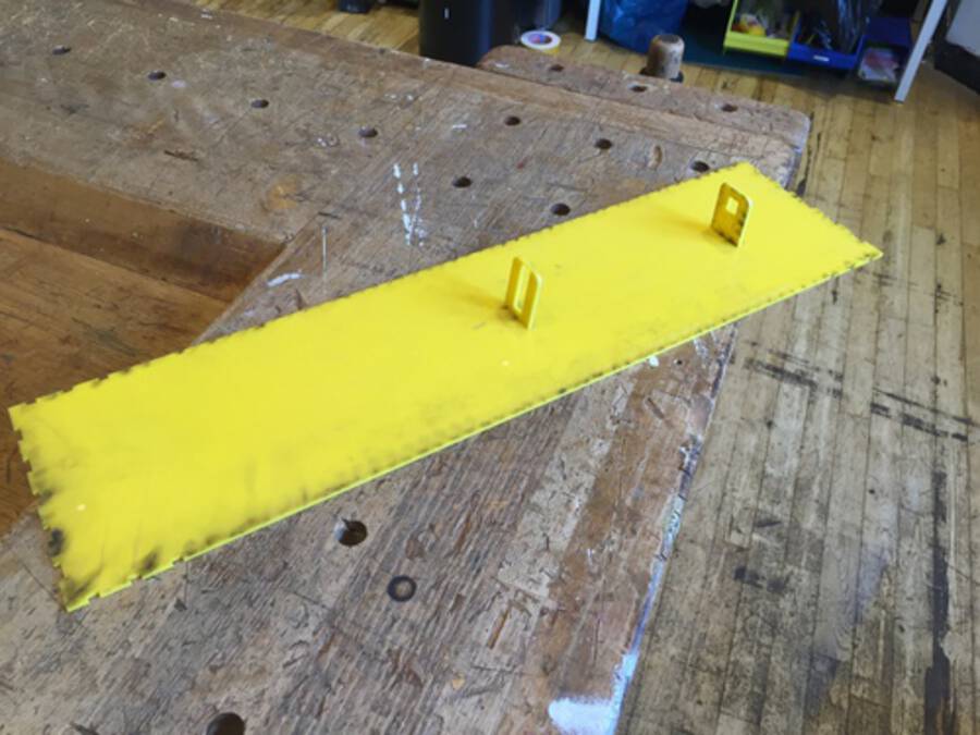
The top shell, with fulcrum and Z axis guide:
IMAGE 73
Image 74
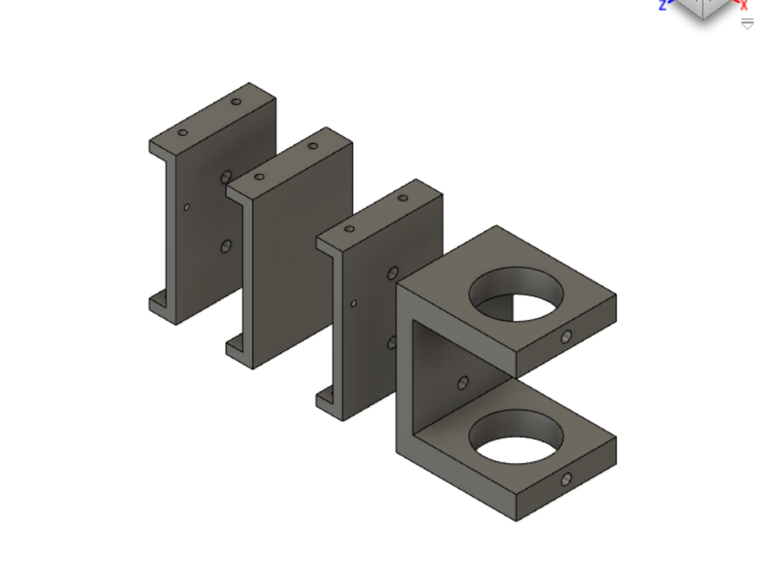
Image 75 We had thought a lot about making the supporting bridge. We considered several fancy designs. But by the time we came to making the bridge, time was running out. So Hyejin and Tessel did a really quick job. We decided to make four boxes with holes in the side. A stick would be run through the holes. The arm can then lean on the supporting stick. These bridge boxes would be placed on either side of the arm. Hyejin made a design in Fusion360 really fast. It consisted of three parts. Two standing faces without holes and two with holes for the stick. Bottom and top of the box are a single square. We decided not to use press fit. Time was running out! Instead we would use the glue gun Harm had found earlier in the day and was happily glueing anything that was lying around loose. We laser cutted the parts and Hyejin, Harm and Tessel glued them together. It all was super sturdy. Or at least sturdy enough. But then minutes before the Lab was closing Harm send the arm too far and it pulled the bridge down with it. We have only tomorrow morning to fox everything. But we will make it :)
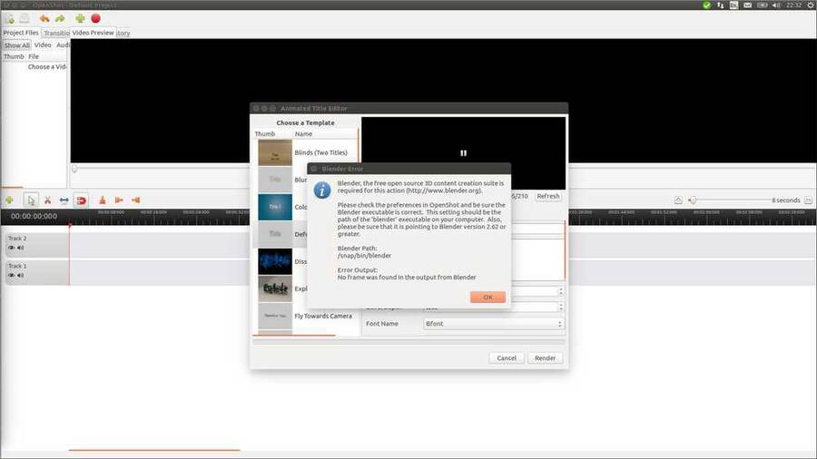
I want to make a 1-minute video for the presentation of the project. I had come up with some animated titles I wanted to use. First I tried OpenShot. To use animated titles it calls on Blender. I like that, open source programs working together. But when I clicked animated titles in OpenShot it wanted to know the path to Blender. Image 76
So on askubuntu I found that `which blender` prints the path to blender. And `blender --version` will tell you its version. So I did, changed the path, but openshot kept throwing up this error. So I abandoned Openshot
I've used Final Cut Pro a lot in the past. So I opened an old computer that still had it installed. But I suspected FCP won't import mp4 video's. I remembered it did not like video's from smartphones way back when. And indeed it FCP did not recognize the video format. This is an ancient FCP version, things may have improved in the meantime.
I considered making the titles in FCP exporting them and edit them onto video in Openshot. But that might give problems with transparancy. That is, having the titles overlaid on the video. Plus, when I looked at it, I realized FCP title program is not all that fancy.
On to the next open source video editing program. Rutger had recommended Kdenlive. The interface is a bit different than usual. For instance you don't import a file under the `File` but under the `project` dropdown menu. When I found how to start making a title `project > open title clip` there was a button `animated title`. Here it seemed I was able to do what I wanted to do. So I decided to go with Kdenlive.
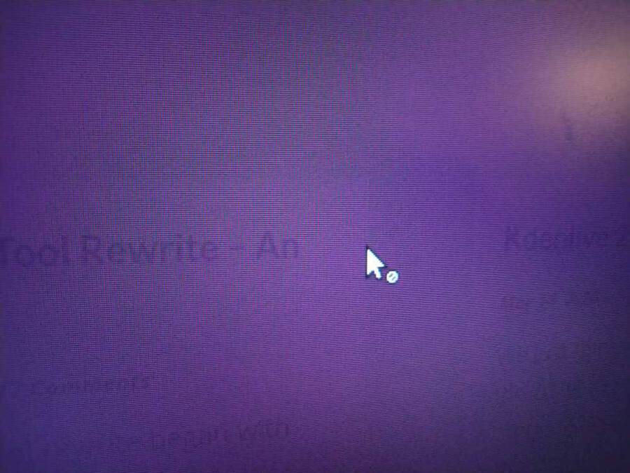
But the program is buggy. It has crashed multiple times already. Twice now it has disabled my mouse. System wide.
Image 77: Mouse with a forbidden sign attached to it.
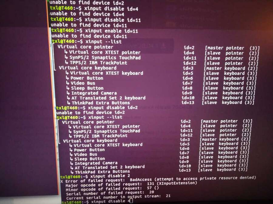
So off to the forums it was. First I searched for Kdenlive mouse/cursor diabled but that was too narrow a search. So I just looked for how to disable and enable the mouse on Ubuntu. I found an answer: `xinput --list` will list keyboard and mouse devices. Then `xinput disable X` where X is the number after the `id=` entry. Afterwards you can enable everything with `xinput enable X`. But when I run this command I get an error: `attempt to access private resource denied`. Sudo does not solve it.
Image 78: xinput error
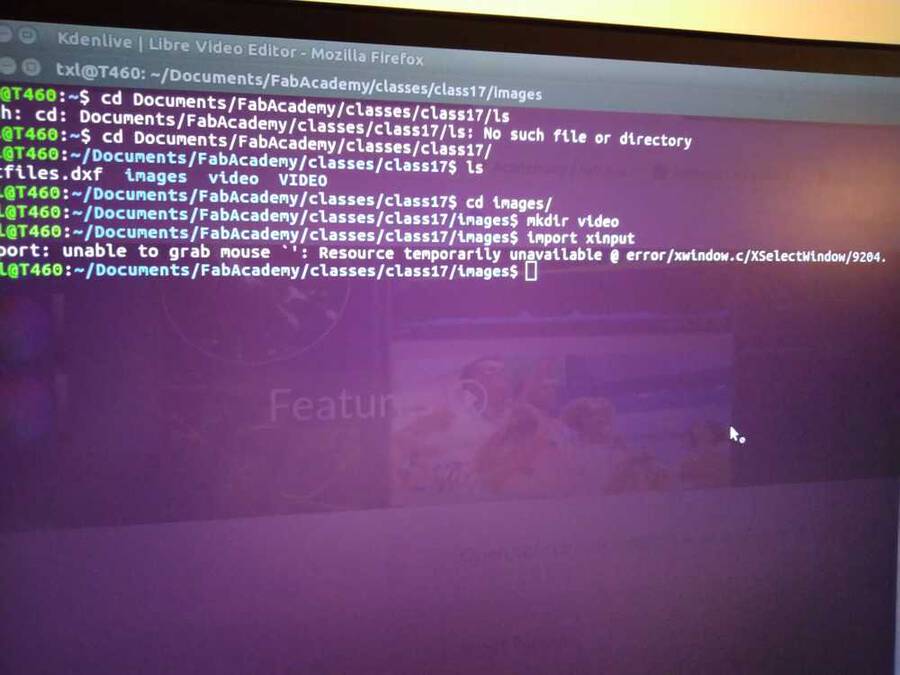
I wanted to make a screenshot but ImageMagick won't work without an enabled mouse. Image 79: So here is a photo of my screen rather than a screenshot.
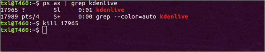
What worked in the end is `ps ax | grep kdenlive` this gives the process id (pid) of the kdenlive program. Then use the pid to kill the program with `kill [pid number]`. Then Kdenlive shut down and I had my mouse back.
Image 8o
Henceforth I am running Kdenlive in the terminal. That may be telling me what is going on and hopefully will make it easier to kill it if necessary.
I also remembered I did not just install kdenlive with `sudo apt-get install`. Instead I installed the latest version in the terminal: `sudo apt-add-repository ppa:kdenlive/kdenlive-stable && sudo apt-get update` and then did `apt-get install kdenlive`. Maybe that package is not stable so I uninstalled with: `sudo apt-get remove kdenlive` and then did `sudo apt-get autoremove` to remove all the associated packages. Did `sudo apt-get update` and `sudo apt-get upgrade`. Then reinstalled by `sudo apt-get kdenlive`.
That did not help. Kden forum advised to install missing package `libeigen3-dev` And another package: as per the forum `apt-get install libavcodec-ffmpeg-extra56`. Then from the kden page I installed the app-image. Download it, set permissions to `allow executing as file program` and double click on the app-image. An app-image is a stand-alone version of a program. Rather than the usual Linux way of installing different packages and placing them on different locations on the computer, the app-images contains everything in one place. This does mean it will not update or upgrade. You need to reinstall it if you want a newer version. This app-image versus apt-get may also be the reason Openshot and Blender aren't working together. Blender is installed with SNAP, the Ubuntu version of app-image, and Openshot through good-old apt-get. But I am not going to check that out now.
After installing Kdenlive via the app-image it worked like a charm. It took a short time familiarizing with the fast keys and such things. I quickly went through this tutorial that explains the basics about Kdenlive's animated titles. And pretty soon I could work with it as fast as with other editing programs I’ve used. It's nice that program UI designers more or less sticks to the same interface. Two things took me some time to find: The Properties Pane is necessary for making transitions and effects. It took me some time to open it. In the end I found out The `Properties pane` has been renamed to `Effect/composite stack`. Select under `view`. The other thing was to get the timeline to render the footage. That turned out to be `Shift return`. Make sure the blue ribbon at the top of the timeline is covering the area you wish to render. The result of the video is on top of this document
Final files
3D files
Arduino Libraries
Arduino files
Json webserver websockets
Our group
The assignment
Our ideas
Dog project
Autonomous following systems
Recognizing the ‘owner’
Power supply
Structure
Face (fur/outside)
Remote control
Idea 2
FabConnector: Drawing machine that can be operated remotely over the internet. Florent in France will move the drawing machine in Amsterdam.
Requirements first spiral
Coding and networking
Connecting the stepper motors to arduino
I found on http://hobbycncaustralia.com/Instructions/iI9wirestepper.htm website I found steppers with the same wiring.
Connection to the internet
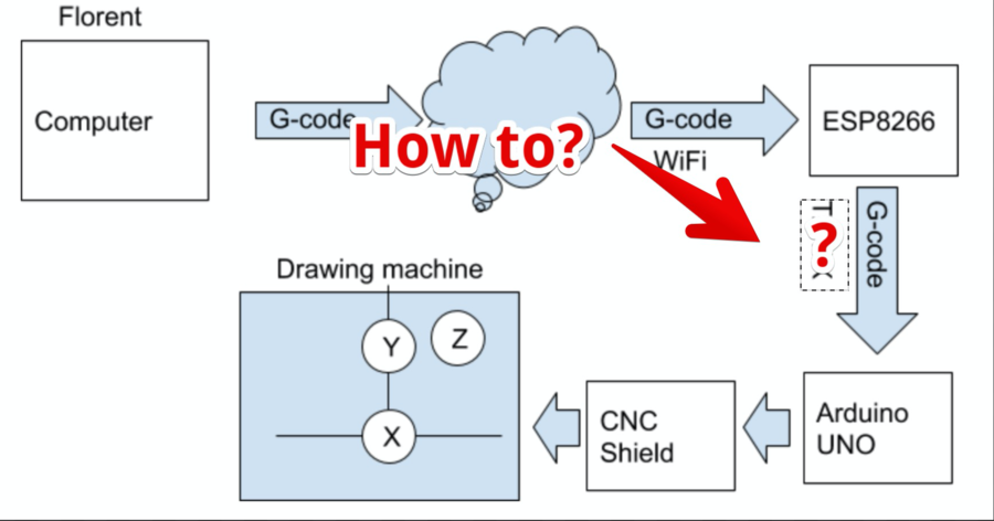
How can we work remotely together?
How can we get data from ESP board to Arduino UNO?
Part of the system being worked on marked in green.
Sending G-code from ESP6266 to Arduino UNO using TX/RX
How to send the Gcode data over the internet?
I was so naive, when I want to build a server, I use linux 95% of time…
Azure management for linux have a f#### bug on it, Websocket activation doesn’t work at all !!!
Finding the range and add end stops
Making a connection between France and the Netherlands
Port forwarding:
G-Code TX/RX
Using Azure to connect between France and the Netherlands
What is the maximum feed rate of these steppers?
The remote control (wemos)
Building the platform
Cardboard casing
Getting the pen down / moving the Z-axis
Supporting structure
First assembly
Making the casing more sturdy
Building a supporting bridge
Making the 1-minute video
Kdenlive