Final Project - Development
Description of the project
Project management techniques
In the very first lecture of the FabAcademy Neil introduced project management techniques: time-supply and spiral development. They immediately caught my attention. The combination of these two techniques helps you to finish a project within the time that you have.
Time supply
Often when we plan projects we start and calculate the amount of time we think we need for it and then we try to find that time. This technique is called time-demand. Time-supply project management reverses this approach. You look at how much time you have, say a week to finish an assignment, and then you fit the project in that available time. It forces you to be creative about accomplishing the project: find quick solutions and short cuts. It helps you not to quit when you run into an obstacle but rather, find a creative way around it. Projects don’t have to become less ambitious, it’s just a different approach that stops you from procrastinating and my personal trap, getting stuck for hours on a little thing that does not work. In the first weeks of the FabAcademy I still worked according to the time-demand approach. In the ‘what went wrong’ section, I documented week after week that, in retrospect, I was stuck too long on an insignificant detail of the assignment. Over the weeks this became better and I more and more adopted a time-supply working approach. During Machine week time-supply really paid off. What had seemed an impossible task at the beginning of the week was accomplished at the end of it. We managed this by constantly re-assessing the requirements we set for our selves. If a job took to long too accomplish, we either scaled down the requirement in terms of ambition or discarded it all together. A good example were adding end stops to our machine’s three axes. We thought it would be a simple job and just add it to our machine. But it turned out to be a hard problem. We decided to discard the requirement of the end-stops. Should we have used a time-demand approach we would have lost hours and hours on this requirement.
Spiral development
Spiral development is a form of parallel development. Rather than planning a project in a linear way and schedule one phase of the project after another, you develop different parts of your project in parallel. You work in circels: you take your large complex project and break it down in small circels. Each circel is a complete development cycle from design to working prototype. It’s called spiral development because each new circel builds on the previous one. For instance, if you want to have your networking device to be capable of mesh networking and output received messages to a monitor. The first spiral would be to get mesh networking going. In the next spiral you get the monitor to work on your board. And during the third spiral you combine the two parts by having incoming messages displayed on the monitor.
In this wat you add complexity to your project. This approach has multiple benefits. It is more fun because you accomplish things in short intervals. Also, debugging of simpler prototypes is easier than debugging one huge complex project at once.
Triage
Triage stems from war time field hospitals. It is a way to decide who’ll receive medical care when there is not enough capacity. There are three categories: those patients that can wait, those that need immediate care and those that are beyond saving. In project management you can also apply triage. You need to decide which jobs are most urgent and also which jobs are beyond saving. Letting go of a task you already invested in actually isn’t that easy. But being able to cut them helps finishing the project.
Planning
Week 21 - Deadline July 1!!!
In this week I’ll either work on my stretch goals or catch up on stuff that has not been accomplished as planned.
| Task | planning | status |
|---|---|---|
| Film Waag | Monday, June 28 | done |
| Add wires to the keyboard | Monday, June 28 | done |
| Add battery | Monday, June 28 | done |
| Add copper to keyboard | Monday, June 28 | done |
| Get blink for all the nodes in the network | Monday, June 28 | done |
| Add finished project footage to video | Monday, June 28 | postponed to Tuesday |
| Add finished project footage to video | Tuesday, June 29 | done |
| Make slide | Tuesday, June 28 | postponed to Wednesday |
| Make slide | Wednesday, June 29 | done |
| Present at the global session | Wednesday, June 29 15.00 hours | done!!!!!!! |
Stretch goals:
- lasercut project name on the casing
- make fitting for board > 3D printing
- mill FTDI
Finished stretch goals:
- make fitting for monitor
Week 20
In this week I need to design and mill my own board and test if the code works. I also want to finish the peripherals like the casing and the keyboard. The primary code is working (mesh networking) but I also want the code for the monitor to work. In the weekend I want to finish the video.
| Task | planning | status |
|---|---|---|
| Design my own ESP32 in KiCad | Monday, June 22 | done |
| Mill and solder the board | Tuesday, June 23 | only got the milling done |
| Solder and test code on my board | Wednesday, June 24 | done |
| design keyboard and dividers + lasercut dividers | Wednesday, June 24 | done |
| Lasercut keyboard | Thursday, June 25 | done |
| Design and lasercut casing for monitor | Thursday, June 25 | done |
| Add battery | Thursday, June 25 | moved forward |
| Stitch the book | Thursday, June 25 | done |
| Program for the OLED monitor | Friday, June 26 | half succeed |
| Program for the OLED monitor | Saturday, June 27 | done |
| Make video | nope | |
| Make a slide |
Week 19
As I am already busy with the CNC I will finalize all jobs I need to do on the CNC: milling a 3D model for the book cover and milling the casing for the device. I also decide to pivot from the ESP8266 to the ESP32. In this week I will mill an existing ESP32 development (the Barduino) to familiarize myself with the chip and the components needed for the board.
| Task | planning | status |
|---|---|---|
| Mill and solder ESP devboard (Barduino) | Thursday, June 11 | done |
| Get mesh networking to work on the board | Friday, June 12 | done on Saturday afternoon |
| Make 3D design for cover of book | Sunday, June 13 | done |
| Mill the design on CNC | Monday June 14 | done |
| Mold and cast the book cover | Tuesday, June 15 | done |
| Check result of cast & finalize the cover | Wednesday, June 16 | done |
| Mill the casing for the device | Thursday, June 17 | done |
| Get the touchpins to work on the board ESP32 development board | Friday, June 18 | done on Saturday afternoon. |
| Record voice over for video with Filip | Saturday, June 19 | done |
| Documentation for global review | Sunday, June 20 | done |
Week 18 project development
Catch up on Make Something Big, the assignment I had missed because of the corona lockdown. I greatly underestimated how long this would take. I scheduled to days but it nearly took a week.
Make something big - kitchen cabinet
| Task | planning | status |
|---|---|---|
| Redo the design to include press-fit | Thursday, June 4 - finish | done |
| Mill on the CNC | Friday, June 5 | fail: only setup the CNC with V-Carve |
| Documentation for global review | Saturday, June 6 | done |
| Redo the design again based on new insights | Sunday, June 7 | done |
| Mill something big | Monday, June 8 | done |
| Documentation for global review | Monday, June 8 | done |
| Sanding and fitting the cabinet | Tuesday, June 9 | done |
Week 13 - Execution of final project
In week 13 I made a project development plan. I’ve written out the different parts of the system. What each part does, what work still needs to be done on them and a planning of when each part will be done.
The mesh networking apparatus will be a modular device. The modules will communicate with eachother over I2C. Mesh networking will be handled by a ESP8266 module.
It will consist of the following modules:
- Master module with ATtiny3216. Function: regulate I2C communication between modules.
- ESP2866 module. Function: mesh networking.
- OLED monitor module. Function: print out messages received from mesh nodes.
- Interface built with Processing. Function: input characters to master module.
- Casing for the modular mesh device. The casing itself is modular, you can add new boxes for when you add extra modules.
- A booklet of handmade paper.
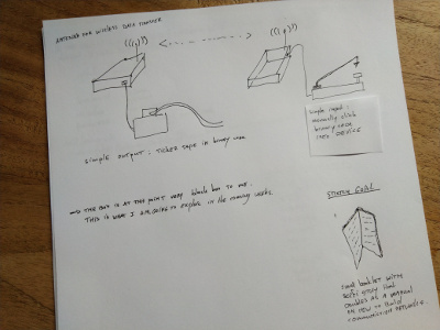
Spiral development 1
Step response board. Function: Keyboard function to input characters directly into master module.
Spiral development 2
SD card module. Function: Saves incoming messages & serves as data input device. (Data can placed on card on computer and ported to the modular mesh device.)
How the modular mesh device works
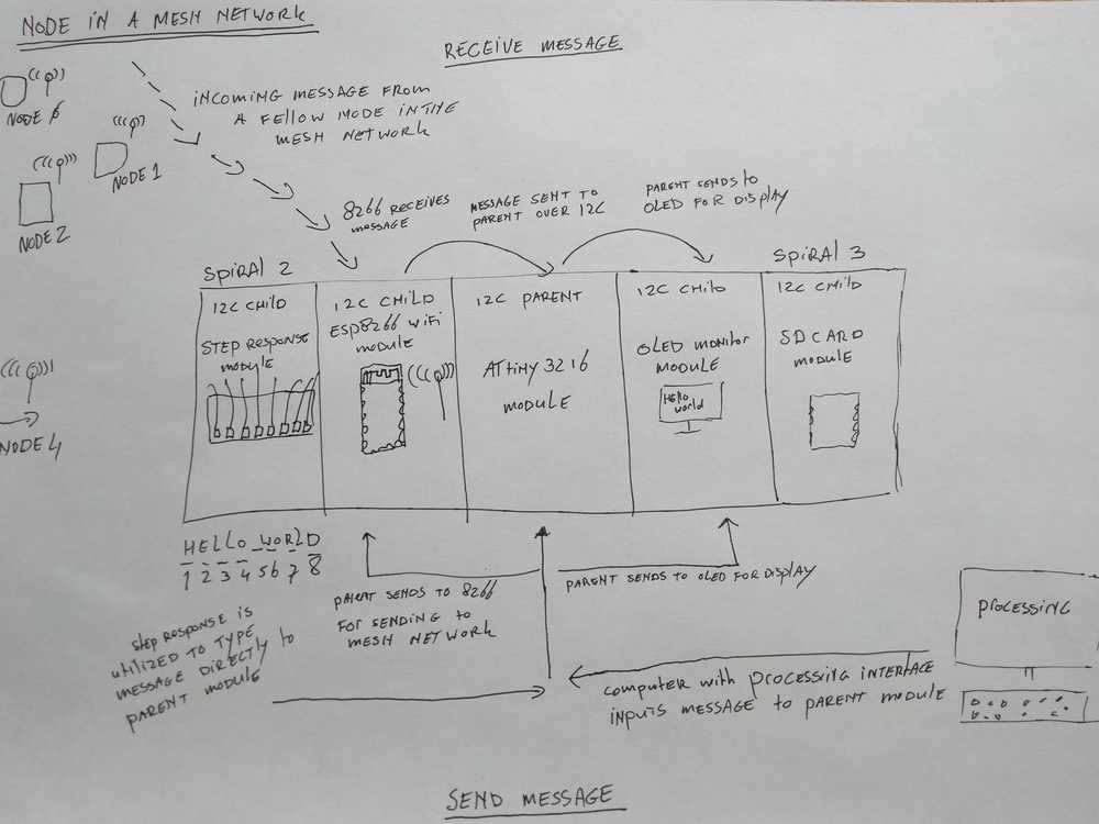
In the middle of the picture is the mesh device. It consists of five modules, each cased within the modular packaging.
In the middle is ATtiny3216 parent module, it organizes communication between the modules over I2C. The ESP8266 module sends and receives messages to/from the other nodes in the mesh network. The OLED module displays the messages.
Receiving messages: A node in the mesh network sends a message to our device. The message is received by the ESP8266 module over WiFi. It sends the data on to the parent module over I2C. Parent sends the data on to the monitor for display over I2C.
Sending messages: Using the Processing interface of a virtual keyboard, we can send a message to the parent module using FTDI. The parent module forwards the message to the ESP8266 WiFi module over I2C. The WiFi module sends the message onto the mesh network. The parent module also sends the message to the monitor for display.
Spiral 2
If time permits the step response module will be added. It serves as a keyboard. The step response sensor is connected to copper pads. Tapping a pad will input a character into the parent module. This way we can input a message with having to use an external computer.
Spiral 3
Add an SD card module to give the mesh device storage capability.
Work to be done on the modules
Parent module
The parent modules function is to route data over I2C.
It will have a ATtiny3216 chip. I’ve gotten familiar with this chip in week11 when making the OLED monitor output device. I choose this chip because it is powerful.
Beside the chip the board will need:
- An array of I2C pinouts to hook up modules. The maximum number of I2C child devices is 1008, so there isenough room for expansion. I will make five I2C pinouts. Four for my planned modules and one extra. I2C only needs to pins, but I will hook up four pins because sometimes a module may need to connect to GND and VCC too.
- FTDI pinout for communication with the Processing interface.
- Battery input for stand-alone operation.
BOM
| component | quantity |
|---|---|
| ATtiny3216 | 1 |
| FTDI 6-pin header | 1 |
| I2C 4-pin header | 5 |
| Battery holder | 1 |
Work that needs to be done for this module:
- Check with tutors if this idea makes sense.
- Check with tutors about power supply over battery.
- Design the board.
- Learn all there is to know about I2C communication.
- Program the board.
ESP8266 module
The function of this module is to communicate with a mesh network. The ESP8266 chip will do the heavy lifting. I will use the Painless Mesh library to get it operating.
Its second necessary capability is data transfer over I2C. The chip is capable of this as well.
It will have an FTDI header to enable serial communition.
It will have 2 I2C 4-pin headers. One is necessary + one extra.
Voltage regulator to regulate to 3.3V the ESP chip wants.
BOM
| component | quantity |
|---|---|
| ESP8266 module | 1 |
| Voltage regulatro 3.3V | 1 |
| Capacitor 1uF | 1 |
| Capacitor 10 uF | 10 |
| FTDI 6-pin header | 1 |
| I2C 4-pin header | 1 |
| Battery holder | 1 |
Work to be done on this module
- Finish desiging the board. (We are currently in networking week.)
- Mill the board.
- Solder the board.
- Master the Painless Mesh library. At a minimum:
- send custom messages.
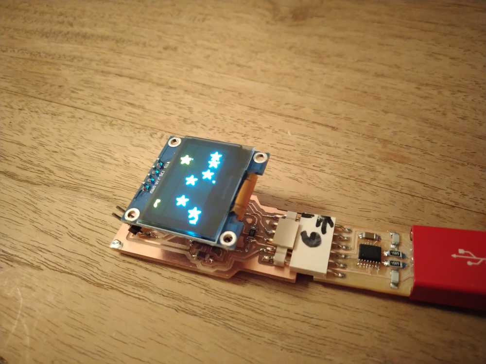
OLED module
The function of this module is to display messages. I got the OLED board to work in week11. However, it needs to additions: I’ve sent data to the OLED over FTDI. But in this set up it needs to be sent over I2C. So I need to figure that out.
The current board does not have its own power supply.
I want to change the I2C 2-pin header for a 4-pin one in case it needs to connect to GND and VCC.
I’ll add an extra I2C pinheader.
BOM
| component | quantity |
|---|---|
| ATtiny3216 | 1 |
| FTDI 6-pin header | 1 |
| I2C 4-pin header | 2 |
| 4-pin female connector for OLED monitor | 1 |
| OLED monitor | 1 |
| resistor 10k ohm | 2 |
| non-polar capacitor | 1 |
Work to be done on this module
- redesign the board for two extra capabilities: A battery holder and a second I2C pin-out.
- Mill the board.
- Solder the board.
- Learn to send data to monitor over I2C.
Processing interface module
The function of the Processing interface is that it provides a virtual keyboard to input data to other devices. I made this in week12 and got it to work with the OLED board.
Work to be done on this module
- Nearly done, just need to finish up the design.
- Get it to work with the parent module.
Step response module
This is a board with a step response sensor. The sensor outputs to 8 wires. The wires are connected to copper pads. When you touch a copper pad data is outputted over serial.
This board took me a long time to get working. I only got to the point where I see output in the serial monitor. I haven’t yet accomplished yo have that output do something. That is why this module will only get attention when spiral development phase 1 is completely finished.
Work to be done on this module
- Translate serial data output into executing actions.
- Have it communicate over I2C instead of FTDI.
SD card module
It will be nice to give the modular device storage capability. However, I think that this spiral 3 phase lies beyond the end of the FabAcademy.
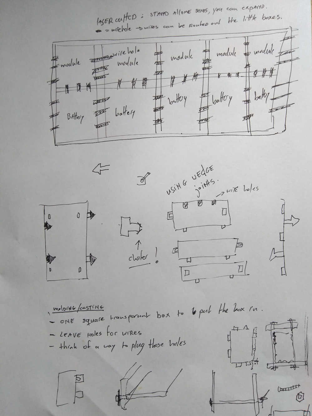
Casing
The casing has modular design consisting of little boxes that each fit one module of the modular mesh device. The boxes can be daisy chained. That way you can expand the box when adding new modules to the device. This will be made with lasercutting.
The parts will be made using the lasercutter. 2D surfaces will be cut out from wood that can be assembled together. Wedge joints will be used for connections between the 2D surfaces. The individual boxes will be chained together using a connecting stick that is held in place using wedge joints.
There will be notches in the surfaces to allow wires to run through.
The box I will make will have room for five modules. Each module will have its own box, and a box beneath it to house the battery holder.
A molded and casted second box will be made to enclose the lasercutted modular casing. This can’t be modular for obvious reasons. But it will be made with parametric design so people can mold the casing in the size of their needs. The casted outer casing will be transparant because this project is about making technology accessible to all.
Summary of everything that needs to be done:
Electronics:
| Action | timing | done |
|---|---|---|
| Understand I2C communication | week 14 | |
| Better mastery of Painless Mesh library | week 14 | |
| Design, mill, solder, program ESP8266 module | week 14 | |
| Design, mill, solder, program Parent module | week 16 | |
| Redesign mill, solder, program OLED module | week 16 |
Interfacing:
| Action | timing | done |
|---|---|---|
| Finish Processing interface | week 15 |
Packaging:
| Action | timing | done |
|---|---|---|
| Design lasercut modular box in FreeCad | week 15 | |
| Lasercut the box | week 15 | |
| Design casted and molded casing in FreeCad | week 15 | |
| Cast the casing | week 15 |
Booklet:
| Action | timing | done |
|---|---|---|
| Make my own paper | week 16 | |
| Make my own book cover | week 16 |
Presentation:
| Action | timing | done |
|---|---|---|
| 1 minute video | week 16 & 18 | |
| Slide | week 18 |
Timeline
Week 14 Networking & communications
- Design ESP8266 board
- Mill & solder board
- Program board
- Understand I2C
- Better mastery of Painless Mesh
Week 15 Molding and casting
- Design mold in FreeCad.
- Cast casing.
- Design wooden modular box.
- Lasercut the modular box.
- Finish Processing interface.
Week 16 Wildcard week
- Make my own paper.
- Make leather book cover.
- Design & mill master module.
- Redesign & mill OLED module.
- Shoot video from milling module for 1-minute video.
Week 17 mechanical design, machine design
- Finalize all the modules and get them working together.
Week 18 project development
- Make video.
- Make slide.
- And probably a whole lotta stressing to finalize everything.
Week 02
It has become clear to me that my final project is too difficult as the initial plan (spiral development: begin simple and add complexity.) So for the first spiral I’ll remove the ‘simplest building blocks’ constraint. First I will develop devices that can actually transfer data. I am especially considering how to create an input device for data entry without having to build my own keyboard.
Week 01
Inspiration & research
See week 10 documentation for a description of the research on what others have done and how it ties into my project.
Henk sent me a link to the Doomsday Communicator. A device for text messaging over LoRaWan. Besides the awesome name, I also really like the interface.
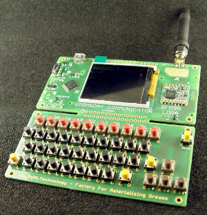
Doomsday communicator by Bobricius.
Types of communication
Perhaps it won’t be possible to rebuild a computer from few input building blocks. Consider also alternative communication forms and devices. Some ideas:
Smoke signals; messengers on foot; messengers on animals; letters; telegram; telegraph; telephone; radio; tv; tube post; books; clay tablets.
On AM/FM radio
I will not use AM or AF radio for this project. It has many pro’s. It’s long distance and radio’s can be made easily and cheaply. However, the electromagnetic spectrum is heavily regulated. And broadcasting on AM FM frequencies is forbidden. That makes it not suitable for this project which aims at networks that can operate autonomously.
Sketch
First sketch of my final project.
Considerations
Input output
I am very used to keyboard for input and screen for output. Can these I/O peripherals be made easily? If not what are alternatives?
| input | output |
|---|---|
| keyboard | screen |
| simple few keys input | simple screen like f.i. the pager screen, 80’s radio clocks, etc. |
| microphone | speaker |
| punchcards | printing paper |
| add machine code directly with electric pulses (on/off switch) | machine code output in physical vorm. F.i. sorting color coded rigns representing 0/1. |
| morse code clicker | morse code tape |