2. Computer aided design
Amsterdam, February 5, 2020
Assignment
- Create a model (model, raster 2D, 3D, mechanical, animated) of your final project. Make pictures and video, compress them and add them to your website.
To do
Explore the list of design programs.
- FreeCAD: model a casing and replicate all 20 actions showcased in the global lecture.
- Gimp + Bimp
- Inkscape
- ffmpeg
- simple screen recorder
- Kdenlive / openshot
- Blender
- Sketchup / Tinkercad
- ncdu - program to monitor file & directory sizes
- Open Scad
- Antimony
- Student agreement
Source files
| Description | source file |
|---|---|
| The casing I made in FreeCAD. | Downloadable FCStd |
| Whiffle ball in FreeCAD based on a tutorial by Roland Frank. | Downloadable FCStd. |
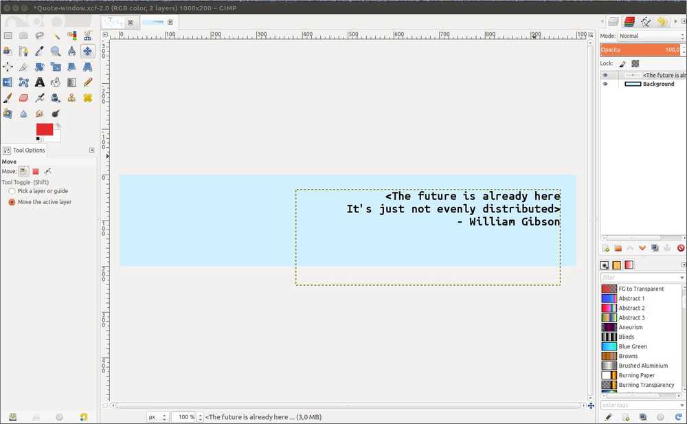
| Gimp project .XCF format file of William Gibson quote | Downloadable zip |
| Inkscape: zip contains a .SVG file, the default Inkscape file and a .DFX file, used for lasercutting. | Downloadable zip |
| Inkscape: 2D design lettering. Zip contains the SVG and .DFX file | Downloadable zip |
| Blender project file | Downloadable zip |
| Light tracer project file | Downloadable zip |
urls
| Description | link |
|---|---|
| Overview week 2 | http://academy.cba.mit.edu/classes/computer_design/index.html |
| Global lecture video | http://academy.cba.mit.edu/classes/computer_design/index.html |
| Global review | https://vimeo.com/391123652 |
| Ffmpeg commands | https://www.labnol.org/internet/useful-ffmpeg-commands/28490/ |
| Compression with ffmpeg | https://unix.stackexchange.com/questions/28803/how-can-i-reduce-a-videos-size-with-ffmpeg |
| Open Shot fast keys | https://cdn.openshot.org/static/files/user-guide/main_window.html) (scroll down quite a bit |
FreeCad
Since I am on Linux Henk advised to skip Fusion 360 and use FreeCAD instead. I just read his own struggle with Fusion on a Linux system so I am glad he spared me that pain :). I jumped right in to FreeCAD without having much of an idea of its purpose and how it accomplishes that. That was not a good method because I could not logically deduce why something was or was not working.
Then I found a fantastic, patient FreeCad tutorial series by Roland Frank of the FreeCAD community. I can highly recommend doing a few of his lessons to get your first bearings.
There are two important concepts that he made me understand. 1. There are different kinds of workbenches that enable you to accomplish different things. 2. Constraints are a very important concept in FreeCAD (probably in 3D design in general but I did not have any experience with this before). A sketch has a x amount degrees of freedom. The idea is to constrain the degrees of freedom. Although, you can leave things unconstrained if that fits your purposes.
General explanation and take-aways:
There are multiple viewers. Enable the Python viewer because it shows when you make errors.
Navigation styles: There are multiple navigation styles, that is, ways your keyboard responds to inputs. The nav menu is situated in the right lower corner of the screen.
Change views of objects: You can change the view of your object (wireframe, as is, etc.). The menu is accessable through icons or right-click.
3D objects come in mesh and solids. Mesh objects consist only of faces while solids have an inner volume. Typical file formats for mesh objects are OBJ and STL. Format for solids is STEP.
- A mesh is a collection of vertices, edges, and faces that describe the shape of a 3D object:
- A vertex is a single point. (The plural of vertex is “vertices”)
- An edge is a straight line segment connecting two vertices.
- A face is a flat surface enclosed by edges. (Some other applications call these “polygons”)
Workbenches
Part design workbench: its primary function is to sketch 2D and extrude or revolve them into 3D shapes. It’s for working with solids.
Part workbench: Works with simple objects (cubes, cylinders) that can be manipulated with Boolean operations (unions, cuts) to create more complex objects. This is the Constructive Solid Geometry (CSG) workflow. Source.
Part design workbench: its primary function is to sketch 2D and extrude or revolve them into 3D shapes. This is a more modern workflow than CSG.
Mesh design workbench is for working with mesh objects
Part and part design workbenches is for solids
Left pane
In ‘Sketcher’ the left pane shows the resolver informing about degrees of freedom and constraints.
In ‘Part design’ the left pane shows data about objects. To move an object, click on ‘placement’. Then 3
dots appear, click those and you can alter the data. Roland Frank selected ‘incremental changes’ but I have not figured out yet what that does exactly.
In the ‘Part’ workbench you can move objects in 3D space by changing the numbers on the X Y and Z axis. Negative values are allowed.
Origin
Roland Frank made it a point to always put the origin (the center of X Y Z axis) in the center of your object. Under ‘view’ click ‘Toggle axis cross’ and place it in the middle by manipulating the axes in the left pane.
You can anchor an object to the axes by clicking to outer vertices of the object and an axis and apply the symmetry constraint ><.
If you want to place the origin in the middle of a face that is f.i. 33 mm long, go to the data panel, click on ‘Placement’, and add 33/2 m (divided by 2, in the unit window). Applying math formula’s is supported in many places in FreeCAD.
Dependency graph
Under tools you can select ‘dependency graph’. It shows how your operations are related. F.i. when you make a sketch and then extrude it in Parts design, you can see in the left pane that header is named ‘extrude’ and in the tree below it is the sketch which is grayed out. In the dependency graph you’ll see this represented in a tree. The dependency graph of my own project became quite a mess. I have yet to figure out how to work more neatly.
Commands
CTRL click allows you to select multiple elements.
Clickin in empty 3D space: deselect all. (Either a constraint tied to the cursor or parts of the object.
Snapping: When circel icon is selected and you move cursor close to an axis or origin, a symbol next to the cursor indicates the cursor is on the spot.
Dot constraint: coincidence constraint. Two points in the same place.
Diameter constraint: set diameter of a circle. Selecting multiple circels gives them all the same diameter.
Dot constraint: coincidence constraint. Two points in the same place.
SAVE OFTEN AND A’PLENTY. FreeCAD can and does crash.
Lesson 1. Turner’s Cube
I started with Lesson 1 - Turner’s Cube This helped me a lot with get a better idea of the function of the workbenches. ‘Part design’ and ‘Sketcher’ for instance are related. You make a 2D sketch in ‘Sketcher’ that you turn into a 3D object in ‘Part design’. Menu icons first appeared to be random and many. But they are actually grouped into edit controls, constraints, shape drawing controls, etc. I am not going to write a step by step on how I did this. The take-aways described above are a generalization of what I learned from this tutorial.
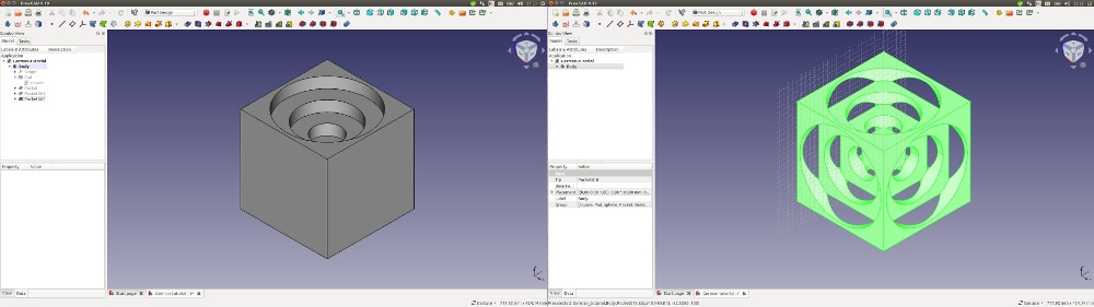 Two screenshots of designing the Turner’s cube in FreeCAD. Based on a Roland Frank tutorial.
Lesson 2. Whiffle Ball
This tutorial was mostly done in the Part workbench applying the CSG workflow. I inserted cubes, added cylinders to them and then applied the Boolean operation ‘make a cut of two shapes’. For instance: insert a small cube in a bigger cube, cut the smaller cube out and you’ll be left with a hollowed out cube.
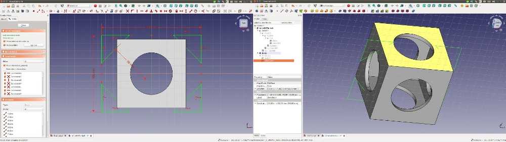 Sketch and object consisting of a cube hollowed out by applying cylinders and Boolean cut operations.
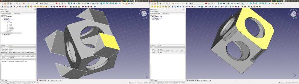 Oops! I did not get the geometrical positions quite right. Still have to practice my 3D senses.
A screen recording of the cube compressed to 154 Kb.
Lesson 3. Arduino casing
Roland Frank also did a tutorial on making an Arduino casing. Since I’ll probaly be making casing for my final project I followed it. First I download a STEP file with a reference design for the Arduino from Grabcad.
Measuring
In order to build a casing for the Arduino you need to know its measurements. Roland Frank showed several ways how to do that.
1. Select 2 outside faces of Arduino model: select measurement tool. Read out the length in the data tab. (This tool is not available in all work benches.)
2. To measure the pins on the board: Take measurement of the pins of the board. In the Draft workbench go to the edit tool group and toggle on center snap and perpendicular snap. These snapping tools are really important to easily select the correct points on the design. Now draw a line from center of hole to side of the board. The length of the line will be shown in de data pane (13,97 mm).
3. Measuring the dimensions of the components of the board. Switch to Part workbench. Insert a cube. Since you placed the origin in the center, the new cube will be inserted in the center. In the Part workbench you can select 2 faces and use linear measurement tool to measure the length between center and outer face.
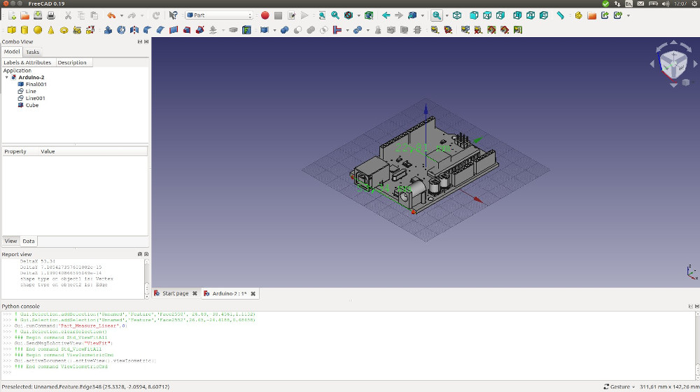
Measuring the downloaded Arduino STEP reference model. Based on the tutorial by Roland Frank.
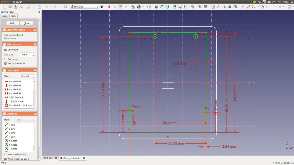
Applying measurements to a sketch. Based on the tutorial by Roland Frank.
Using mapped constraints
The sketch with the Arduino measurements serves as a reference sketch. You can give the constraints a name by double clicking on their represenation. (F.i. the length constraint is represented by a red arrow and a number in millimeters). The named constraints can later be used in a formula. In this case I want to make a wall of the Arduino casing of 1,6 mm. I can use the length constraint of the inner wall as a reference when modelling the outer wall by inserting the formula Sketch001.Constraint.X+1,6mm.
This is done as follows:
- Close the sketch on which you have modelled the inner wall.
- Open a new sketch, draw a second triangle around the previous one.
- The constraints of the outer rectangle need to be mapped to the inner rectangle.
- Select outer points of outer rectangle.
- Click horizontal length constraint.
- Click circle icon in the box.
- Start typing the name of the sketch you want to map to.
- Press ‘C’ for constraints to appear.
- Type ‘Constraints.X’, the value of constraint X now appears.
- We want an offset of 1 mm and a wall thickness of 1,6 mm. So the outside dimension of the model, need to have the measurement of constraintX + 2x offset (2 mm) & 2x wall thicknes (3,2 mm). The formula is: Sketch.Constraints.X+2mm+3,2mm.
Note: you must define the unit sort. In this cas ‘mm’ otherwise you’ll get an error.
You must also insert a dot after the constraint and type X.
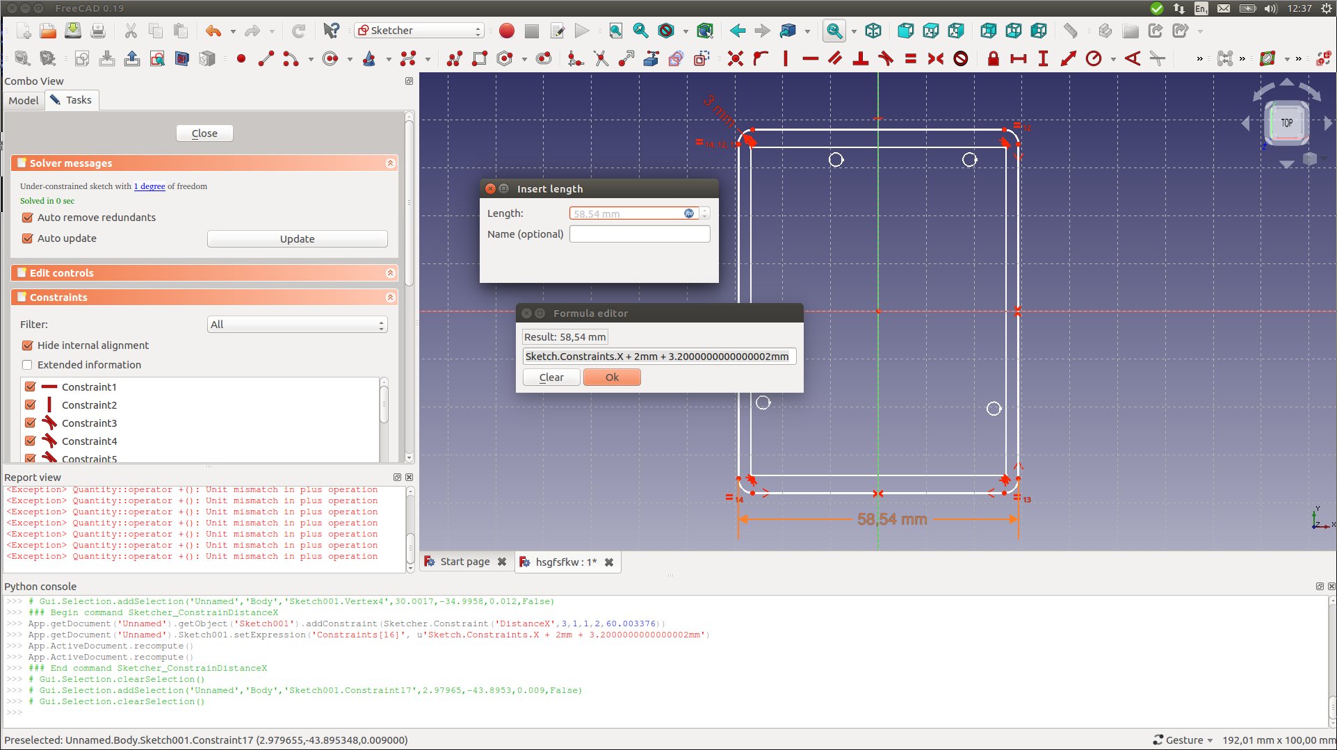
Applying a formula to named constraints.
After creating and closing the sketches I continued as follows:
- Apply padding. Choose 2 dimensions. 1th length 11 mm, 2nd length 1,6.
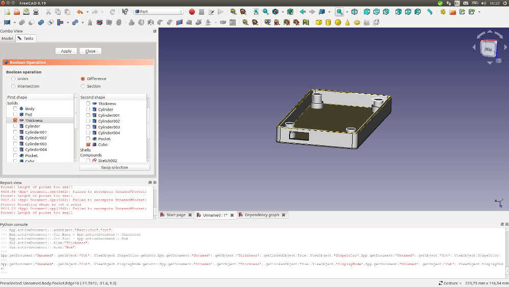
- Apply wall thinkness: select top face.
- Switch to Part workbench.
- Make sure to select only top face.
- Apply thickness.
- Apply a negative value to have a wall in the direction of the inside (-1,6 mm).
Padding of the pins:
- Select reference sketch.
- Edit > duplicate selection.
- Part design workbench: ‘map sketch to face’.
- Choose duplicated sketch002. You can select which dependencies to duplicate. Unselect dependencies.
- Select bottom face apply map sketch to face & choose sketch002.
- Go to sketcher. Select four lines and toggle to construction mode, the lines now become blue. This ensures they will not be used for the upcoming pad operation.
And here is where I got stuck. The padding of the pins ended up in a padding of the entire surface. Over and over again. FreeCAD’s undo operation does not work as I would expect. In most programs the last action you’ve done is rolled back. In FreeCAD this does not appear to be the case. When I hit CTRL Z it seemed as if nothing happened. The Pyhton viewer would print undo 0 or something. Keep hitting CTRL Z and suddenly your back to the first rectangle on your first sketch. I’ve looked online but found no answer. There must be some logic to it but I have yet to figure it out.
Next to CTRL Z’s behavior, copying a project also does not appear to be straight forward. I hoped to save a copy of my project on a certain point in order to start from there if (rather when) the primary project failed. But copied projects would not respond to any input. This resulted in me doing the beginning of this Arduino project over and over again till I hit the padding wall & failed again. It this point I got rather frustrated. I abandoned the project. But I should’ve done that sooner. (See the ‘What went wrong’ chapter.)
My own casing
After that I started to fool around with the program myself by making my own casing. It was far more crude than Roland Frank’s. And more importantly, the resulting files will probably not be printable by a machine as they contain many mistakes. But having to think about how to do things myself did get me engaged in the program in a different way because I now had to solve the puzzles myself.
My crude casing.
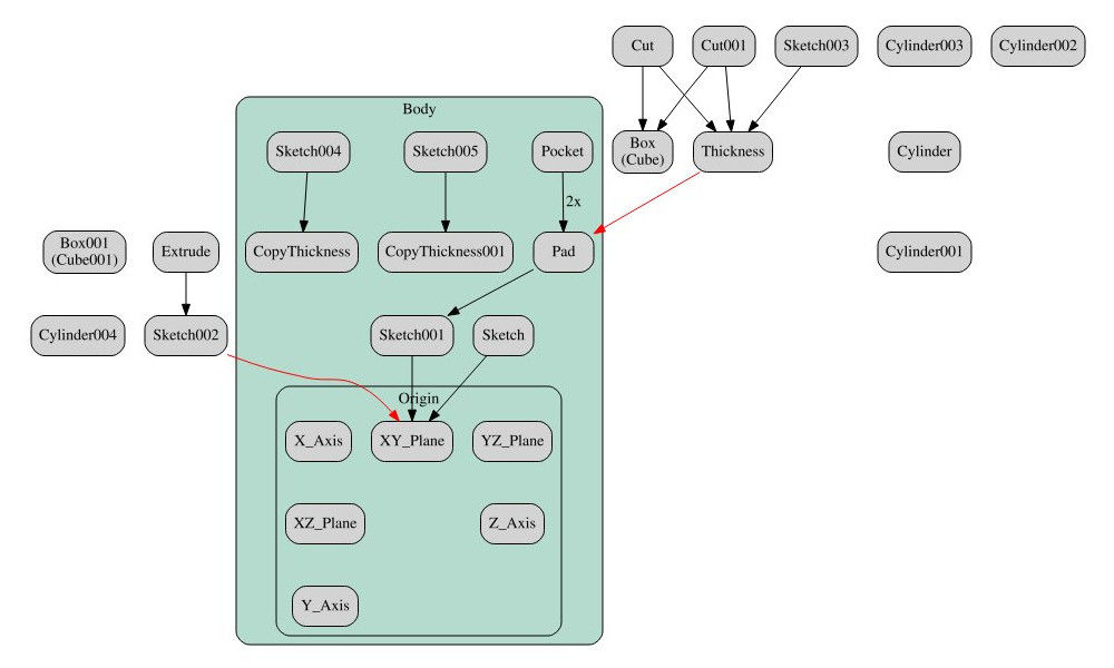
My messy dependency graph.
FreeCAD Urls
Here is the Freecad manual.
Here are Patient FreeCAD tutorials by Roland Frank Learn FreeCAD tutorials
2D design
2D design tools divide in raster and vector tools. Raster tools store individual pixel values. Vector tools describe paths or vectors. Source: Anke Brocker, class of 2018.
Raster image:
Pro: image is clear.
Contra: inflating deprecates image. High res = heavy weight.
vector image:
Pro: Scaling does not result in lack of quality.
Con: hard lines, no gradient.
Gimp
I already knew Gimp for manipulating photos and creating simple text-based images. I made a banner for my website. It was only 16kB but tried if I could shrink it further with ‘imagemagick’. I did convert to .jpg but that made it 18 kB. convert -quality 50% reduced it to 10 kB but quality was lousy.

Here is a screenshot of the .XCF project in Gimp
In Gimp it often occurs that you are using tools and nothing happens. Here is a webpage aptly named ‘Getting unstuck’.
Inkscape
Inkscape is an open source graphic design tool. You can render vector shapes and text with it. I’ve added this section in week16 because my documentation of week02 lacked documentation on a vector graphic design tool. So I know by now that Inkscape is used for preparing design files for the laser cutter. I’ll describe that process here because in week16 I used the laser cutter and realized I had already forgotten how to prepare files for the laser cutter. So it will be a good refresher.
On Ubuntu you can download Inkscape with:
sudo add-apt-repository ppa:inkscape.dev/stable
sudo apt update
sudo apt install inkscape
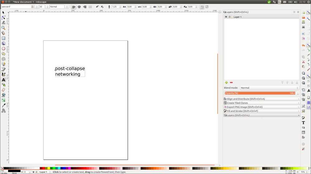
When you open the program it launches a new project. Under file > document properties you can set the dimensions of your project. Here I’ve added some text which you can do by selecting the A icon on the left of the panel
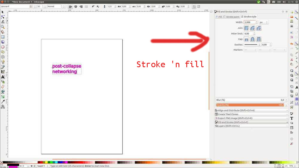
An important function is fill and stroke under object > fill and stroke. If you click it the fill and stroke panel will appear on the right. It is grayed out until you select an element in your design. The panel has two tabs. Under the first one you can change colar and gradient. The second tab is important. Here you can set the width of you strokes.
If you have really thin lines, you won’t be able to see them. If you don’t want to use fill and stroke you can also adjust the view under view > display mode > outline. I’m writing both these options down because in week16 I ran into this problem of invisible lines.
In week03 I did a general Inkscape tutorial. Here I will just look at Inkscape in relation to the lasercutter.
Wiki.imal.org gives some general info in Inkscape for lasercutting:
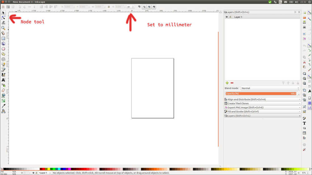
The lasercutter expects millimeters but Inkscape is set to pixels by default. Adjust to mm or your lasercutted object will significantly shrink.
Stroke width should not matter because the lasercutter decides its own width. But if you want to be precise you can set the stroke very small 0.01mm and use display mode to make it visible for yourself.
When you scale an object, stroke width will be scaled proportionally. Not the best thing for lasercutting. You can prevent this: under preferences > transforms uncheck scale stroke width and scale rounded corners.
Paths
Information for this paragraph was found on tutorviacomputer.com.
The most important thing I forgot in week16 is that for lasercutting you need to convert your object to a path: Path > object to path. Converting to paths can not be undone.
Paths consist of nodes which are represented by squares or circles. The pieces between the nodes are called segments. You can manipulate the nodes with the nodes tool. When you click the nodes icon in the left pane, new icons appear at the top of the panel: the nodes workbench.
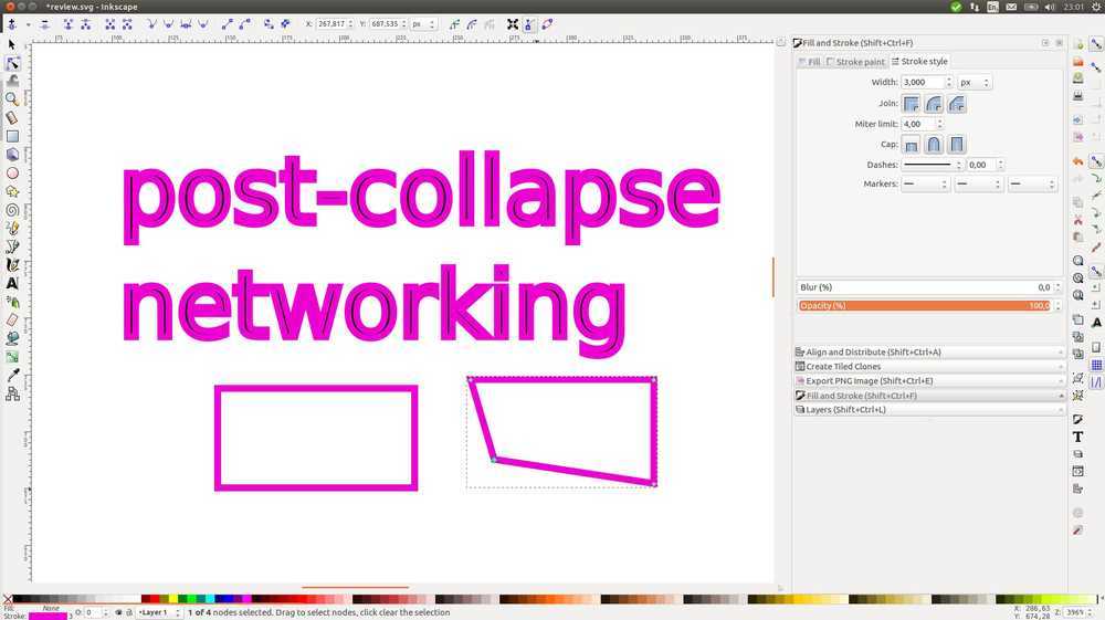
In this screenshot you see two identical squares. The one on the left has been turned from an object into a path. I pulled on the lower left node.
In case of a text, you can select the entire text and turn it into a path. But to see the nodes you must click an individual letter.
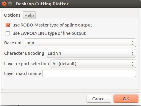
You export to .DXF by using save as. A window opens: Select ROBO-master and unselect LWPOLYLINE. Set base unit to mm.
Preventing Inkscape from shrinking your design
When you made a design for the lasercutter or CNC machine in another program, you often run it through Inkscape to prepare the file for the machine. It can happen that the design comes out smaller. You load it into the lasercutter software and the design is a fourth of its original design. There are two ways to deal with this.
1. Open Inkscape, open file . document properties. Set default units to mm. Then use import to import your design file. Don’t use open. If you open the design any other way, Inkscape’s document properties will start with pixels as default. Even if you change that later, chances are your design is already shrunk.
2. If this does not help, you can do a work-around. In Inkscape, when the pointer is selected the size of the design is shown at the top of the panel. Make sure you selected your entire design. Then in the lasercutter software, you can adjust the size of the design to match exactly the one shown in Inkscape.
2D design
I added this segment in week 16 to complete my documentation. I’ve done so much 3D design in the last couple of weeks that I really had to think hard what one designs in 2D, hahaha. I’ll use Inkscape because I refamiliarized myself with that last night for the segment above.
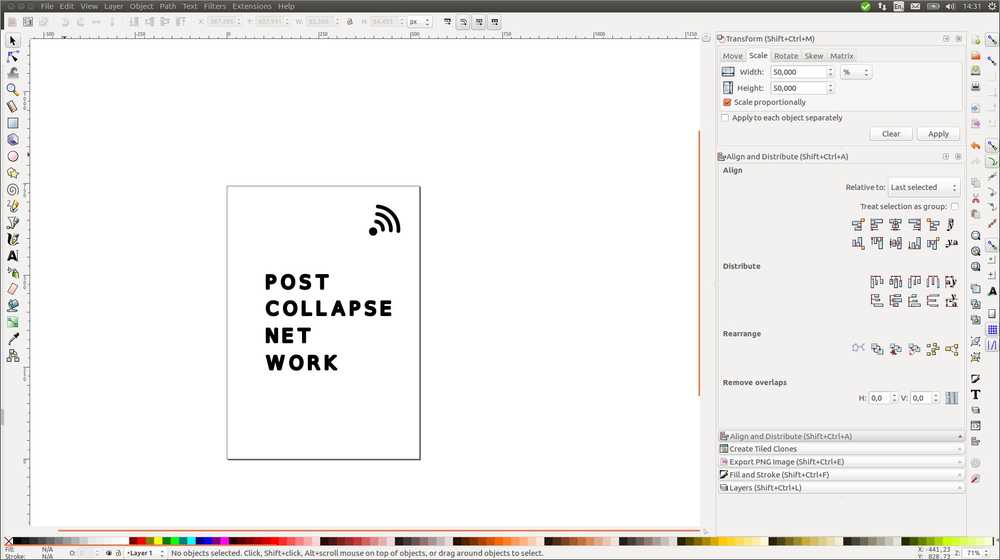
But I’ll design the lettering/logo of my project which is named post-collapse network. I may use the lettering for the cover of my book (if there is time to make a second mold during wild card week). Therefore I set the dimensions of the Inkscape project to A5: 148mm x 210mm.
The letters need to have special properties if I want to mill them on the CNC. They ned to be big enough for the drill to reach in. I used 10mm in week16 and that worked well. There also needs to be much spacing between the letters for the drill to reach. To have an idea about the dimensions I want to view the grid and set it to 1 mm. You can toggle view grid on and of under the view dropdown menu. You can change the settings of the grid under file > document properties > grids.
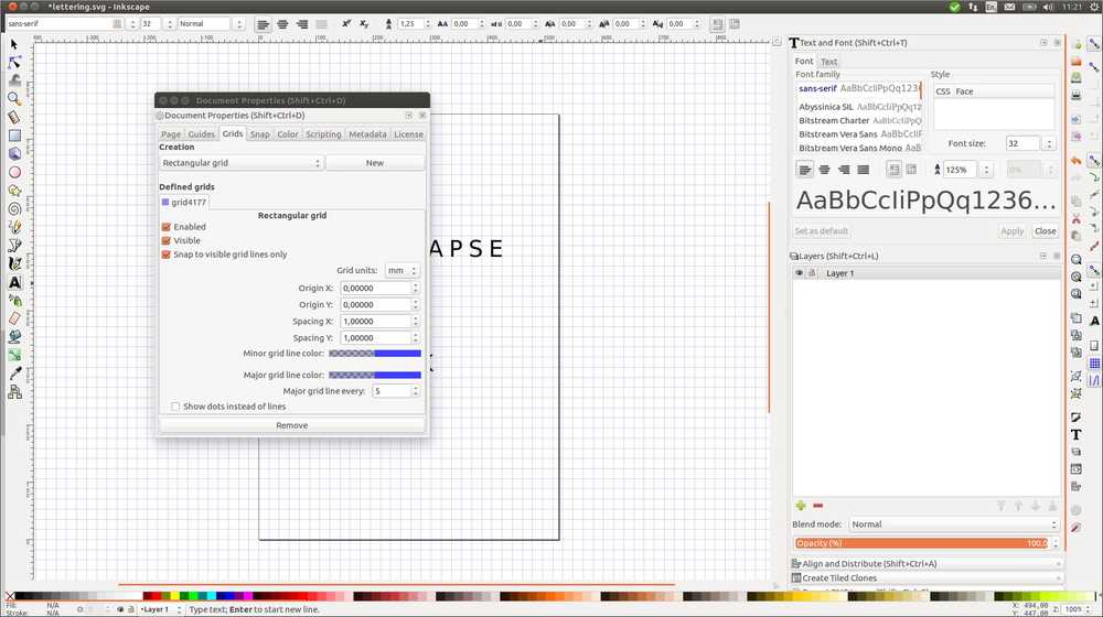
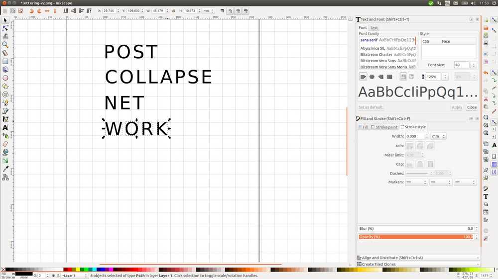
In this picture the text icon is selected. At the top are little windows with nubers, here you can change font size, spacing etc.
I also shows the grid settings window.
You can see a panel at the left. It shows the font size. You can not use this to change the font. You need to do this at the top of the panel.
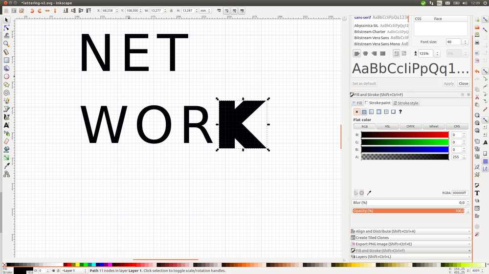
I want to make the thickness of the fonts 3mm so the 3mm drill can reach. You need to turn the object into a path path > object to path. Then ungroup the word into individual letters object > ungroup.
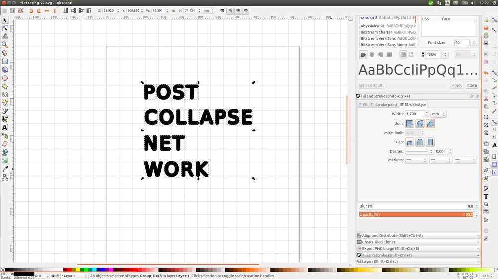
To make the lines thicker I want to use fill and stroke. Under the first tab select a stroke paint. It is set to default to none. And so long it is set to none, anything you do under the second tab stroke and style won’t take hold.
A select all do object to path, ungroup, selct stroke paint flat color and set width to 1,7mm. The 1,7mm is counter intuitive since I want the width of the lines to be 3mm. But I checked against the grod background and this is what gives 3mm lines. I also change the join from miter join to round join as the CNC machine does not like straight corners.
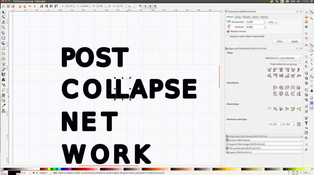
I want to set the letters all 3mm apart. Select a letter. Place it exactly at the rim of the previous letter. Select object > transform. Under the move tab, enter 3mm and click apply.
To align the letters exactly to each other before moving them: Align and distribute. Select last selected from the dropdown menu. Select the two letters by holding the Shift key. Then align keft edges of object to right edge of the anchor.
To have all first letters of the word be aligned vertically, I want to snap to grid. This is an icon on the right side of the panel. However, snapping seems to happen only at 1mm. So to adjust snapping distance: file > document properties > snap to grids. But none of this works. It won’t snap to grid.
I want to change the length of a move step. That is, when you use the arrow key to move an object. edit > preferences > steps > arrow keys move by. I set it to 0.1mm and use this to place letters on the grid line instead of snapping.
Then, I align the letters as described above. And then I move the letter 3mm as described above. Repeat for all letters.
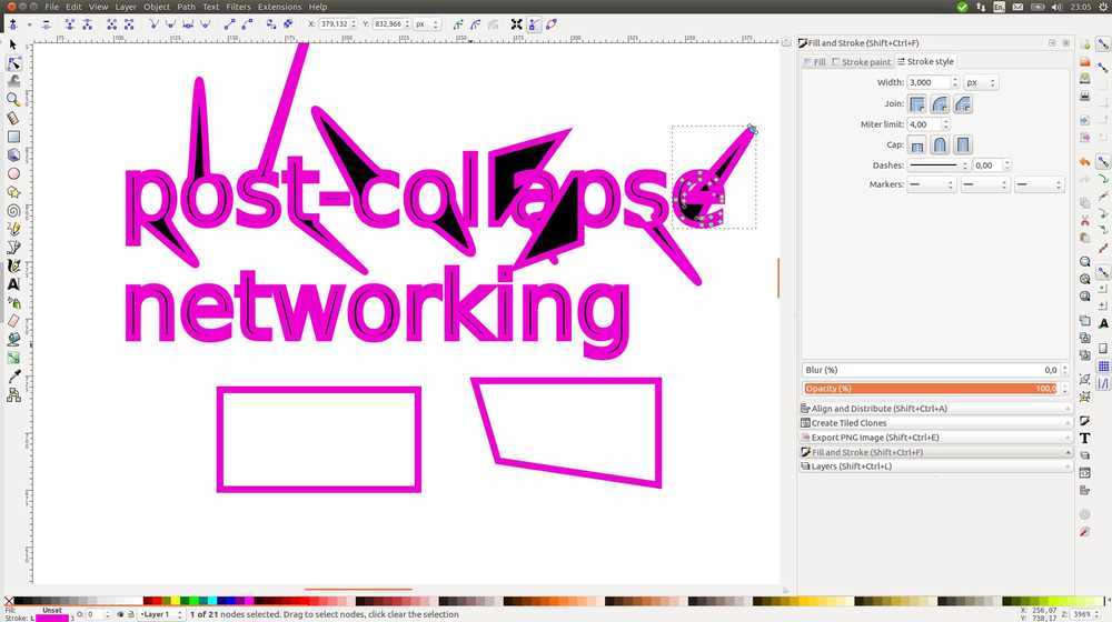
For the logo I am using the wireless signal symbol. Final design:
But I have a problem. The nodes aren’t at the edges of the letters. That means the lasercutter won’t cut at the edges. This is probably because making a line thicker with fill and stroke does not translate to it being the actual outline. That’s why you should set it to 0.04 to see the real outline. This is done by selecting the node tool and and clicking convert selected object's strokes to path.
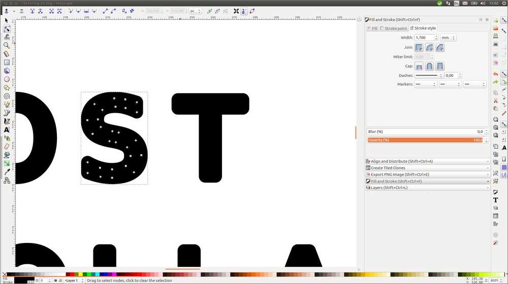
See the difference between the ‘S’ and the ‘T’:
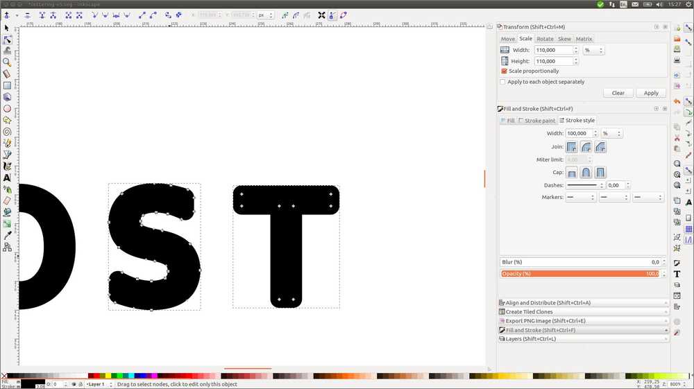
Oh, there is an easier solution. When changing your object to a path, you can choose stroke to path instead of object to path.
Rendering
This section is also added in week16 to complete the assignment and documentation.
Light tracer
At the suggestion of my global reviewer Yuichitamiya I try Light Tracer. This is a rendering program that operates in the browser. You can load up 3D models and Light Tracer will animate it with physical properties. Like making it look as if it is cast from metal or made from glass.
Firefox has a hard time with Light Tracer. It gives a pop-up ‘a webpage is slowing down your browser, do you want to continue?’. I click yes and after a while the app is loaded. I import the whiffle ball from my FreeCad excursions and the app just immediately turns it into a metal cube.
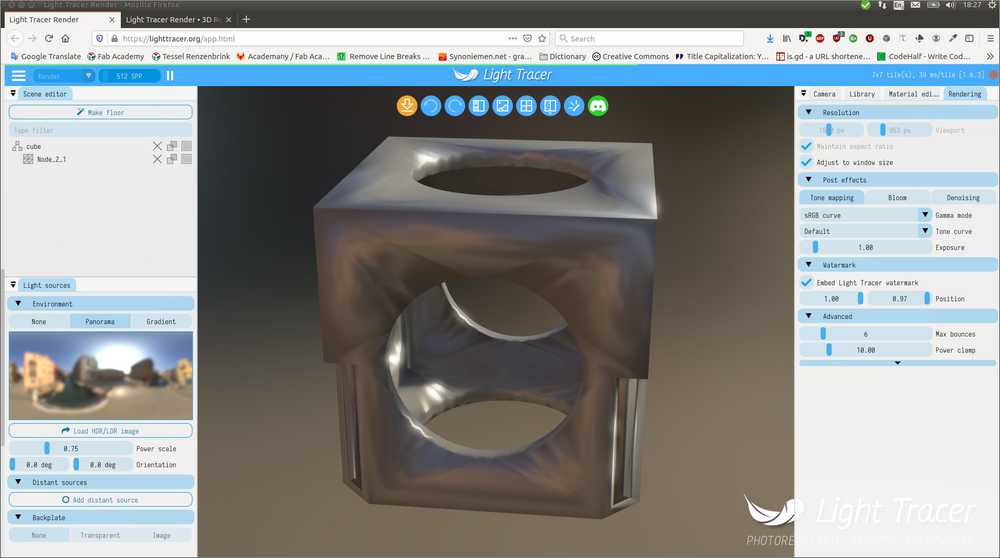
I then select the material editor at the right side of the pane and select glass. As you can see in this picture Firefox has a hard time rendering. This is after a minute or so. 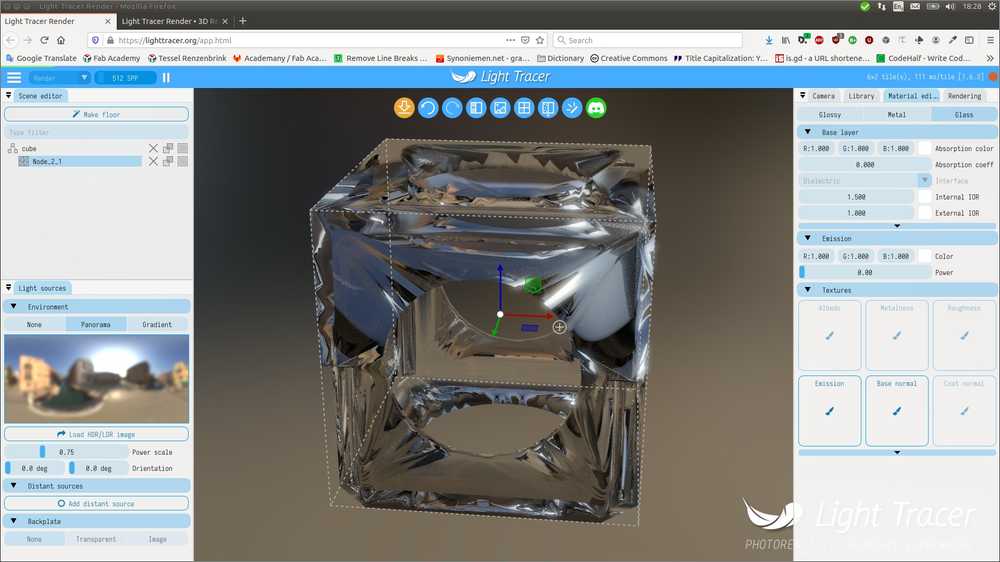
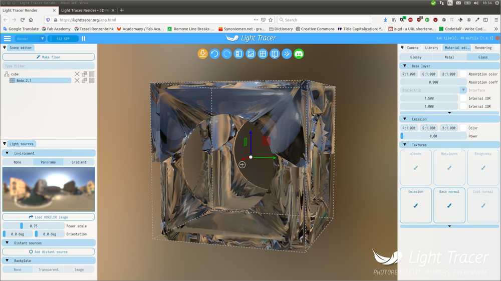
I reload the page and it comes out a bit better:
There are quite some settings you can play with like background, lighting and there is a library of finishes such as copper or shiny metal. You just click on the finish and the cube is rerendered with a new coating. There is also gummy bear green.
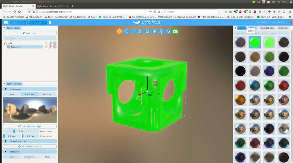
Light Tracer can be exported as a .glb extension. I’ve uploaded the project file to the source files above.
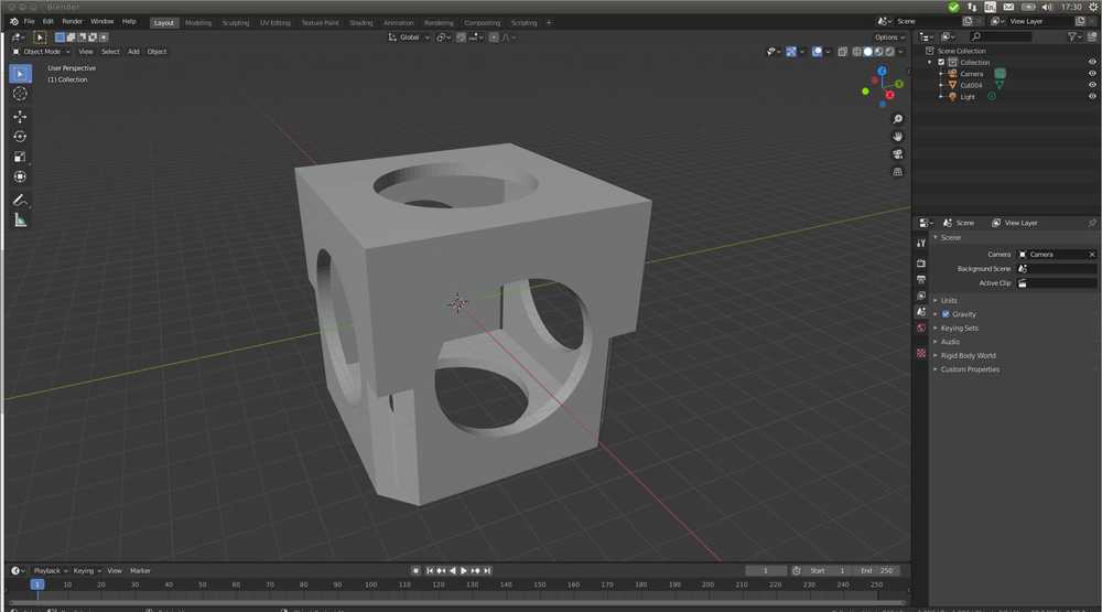
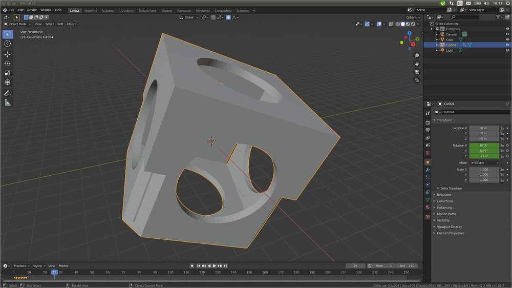
Blender
I am also going to try Blender. During global and regional review I have seen people do fantastic things with Blender, so I want to give it a quick look. It’s open source and available for Linux. To my surprise it was already on my system. I must have installed it in week02 and comepletely forgotten about it. You can download it here for all operating systems.
I start with importing my whiffle ball project from FreeCad. Blender takes many file types and FreeCad exports in many file types. The first overlapping one I see is .OBJ. I export my whiffle ball as .OBJ and click open in Blender. The directory appears to be empty. It takes a while to realize Blender wants you to import .OBJ instead of opening it.
To make an animation you add keyframes. This is a screenshot of the current location, rotation etc. of the object. You can than change the position of the object and add another keyframe. You can then play back the keyframes and you’ll have an animated movie of your object.
Here is the official Blender manual where I looked up how to add key frames.
Set program to object mode at the top right of the panel.
Set keyframe to 1 at the bottom left of the panel.
Make a keyframe by pressing ‘i’. A dropdown menu appears and you can choose what to record. For instance, only location, or location and rotation, etc. I choose location/rotation/scale. Click and a yellow square will appear on your timeline: your first keyframe.
I try zooming out the object a little with a two-finger swipe on my touch pad. And repeat creating a keyframe for each movement. But this does not result in an animation. When I play back by pressing the play button, all frames show the latest screenshot. The reason is probably that I am zooming out but am recording rotation and location etc. So even though I see visual changes on my screen, that what is being recorded does not change. I try a few other settings like visual rotation, visual scaling. But the result is the same for the same reasons. There is probably a camera mode or something that you can use to record what I am doing. For now I just rotate the cube a bit, make a keyframe, rotate, keyframe etc. This works and I have a short animation of the cube turning.
Blender files are stored with a .blend extension. I’ve uploaded the project file to the source files above.
Video capturing and editing
I did quite a bit of video editing in my life. I’m familiar with Final Cut Pro and OpenShot. For the video of the cube above I used SimpleScreenRecorder to record my screen. It’s a pleasant, easy to use program. I edited the video in OpenShot. I have quite forgotten OpenShot’s fast keys. Here is a site with keyboard short cuts for OpenShot (scroll down quite a bit). The biggest challenge is exporting the video as a very light weight file. I tested several settings:
Formats: MP4 (h.264), MP4 (Xvid),
Settings: CIF15 fps, as lower frame rate is lower file size. I settled on PAL 512x288 because of its small screen size.
Bit rate quality to 384 kb/s.
This left my 4 second video at 219 kB and fairly crappy quality. I’m fairly sure the quality - file size ratio can be improved but I’m leaving it for now.
I then used ffmpeg to remove the audio ffmpeg -i video.mp4 -an mute-video.mp4. This got the file size down to 172 kB. For more Ffmeg commands.
Then applied: ffmpeg -i input.mp4 -vcodec libx265 -crf 24 output.mp4. Explanation: ‘setting the Constant Rate Factor, which lowers the average bit rate, but retains better quality. Vary the CRF between around 18 and 24 — the lower, the higher the bitrate. ‘Source: Unix Stackexchange. The result is a 154 Kb with even crappier quality :).
Simple Screen Recorder has compression options build in. I’m going to look into that if that is not an easier workflow.
In the end I did not succeed in self-hosting the video on this webpage. Therefore I am hosting it on
Vimeo and embedding instead.
These are the html codes I tried to host the video:
 <video width="320" height="240" controls>
  <source src="cube.mp4" type="video/mp4">
Your browser does not support the video tag.
</video>
<video width="100%" controls>
   <source src="video/cube.mp4" type="video/pm4">
        </video>
Henk said that coverting to ‘.webm’ with ffmpeg might help to avoid the ‘video format not recognized’ error. I found the command here:
ffmpeg -i input-file.mp4 -c:v libvpx -crf 10 -b:v 1M -c:a libvorbis output-file.webm
But embedding the ‘webm’ file did not work either.
What went wrong
Move on when getting stuck!
Making the Arduino casing in FreeCAD I was unable to replicate a part of the tutorial which prevented me from moving forward. I kept redoing the work to try and get past the error. I spent hours on it and finally did not accomplish it. I got really frustrated and started to really dislike FreeCAD. Finally I let go and started a project of my own, rather than following the tutorial. FreeCAD immediately became fun again. My project wasn’t very sophisticated but having to figure out how to do things engaged my brain much more. It made me having to actively think about how the logic of the program works. To be clear, I could not have done anything without the splendid tutorials. But when I got stuck I should’ve let go and tried other things. Interestingly, after having let go, fooling around more freely and a good night’s sleep, I woke up with a clear idea of what had gone wrong. (The sketch was attached to the wrong face of the object). Keeping stubbornly going at it made me lose my enthousiasm and narrowed my thinking dramatically. I could not think of anything else to do than repeating myself. Note that last week’s ‘what went wrong’ contained this same type of error: not letting go when something does not work. Appearantly there is a larger lesson for me to learn here.
Documentation
I did better note keeping this time but started cleaning the notes up later. That costs a lot of time. Try to integrate proper note keeping on the go.
Error with MkDocs
Spinning up mkdocs serve threw an error:
txl@T460:~/Documents/FabAcademy/tessel-renzenbrink$ mkdocs serve
Traceback (most recent call last):
  File "/usr/local/bin/mkdocs", line 6, in <module>
    from mkdocs.__main__ import cli
  File "/usr/local/lib/python3.5/dist-packages/mkdocs/__main__.py", line 8, in <module>
    import click

File "/usr/local/lib/python3.5/dist-packages/mkdocs/__main__.py", line 8, in <module>
    import click
ImportError: No module named 'click'
Searched online for “mkdocs ImportError: No module named ‘click’” Found github.com/mkdocs where the problem seems to be having multiple pythin versions installed.
sudo apt-get update
sudo apt-get upgrade
No dice
/usr/local/lib/python3.5/dist-packages/mkdocs$ cat __main__.py
I see:
# Disable the warning that Click displays (as of Click version 5.0) when users
# use unicode_literals in Python 2.
# See http://click.pocoo.org/dev/python3/#unicode-literals for more details.
click.disable_unicode_literals_warning = True
I uncomment
#click.disable_unicode_literals_warning = True
No dice. Revert. The above mentioned trouble shooting web page said something about conflicting python installations. This seems to be a problem on my system. I have python 3.5 installed but
python ---version
gives back Python 2.7.12.
/usr/local/lib$ ls
python2.7  python3.5  python3.6
I am considering reinstalling mkdocs. But will that affect my files in the git directory? How did we get the personalized git repo prepared by Fiore on our system? That was by installing git. MkDocs will be in my system’s files, not the git dir. Therefore reinstalling should not affect my git dir.
As we saw in week01 troubleshooting MkDocs: If programs working together, f.i. MkDocs and Material-theme, are installed by different installers, f.i. apt-get & pip, stuff does not work. Yesterday there was another Python install for FreeCad. Maybe that Python installation is now interfering with MkDocs.
When I request
python --verion
It prints Python 2.7.12
But my MkDocs is in
/usr/local/lib/python3.5/dist-packages/mkdocs
But this is normal behavior, see AskUbuntu
I then decided to uninstall mkdocs to re-install. But that trew an error too:
uninstall mkdocs
txl@T460:~$ pip uninstall mkdocs
Found existing installation: mkdocs 1.0.4
Uninstalling mkdocs-1.0.4:
  Would remove:
    /usr/local/bin/mkdocs
    /usr/local/lib/python3.5/dist-packages/mkdocs-1.0.4.dist-info/*
    /usr/local/lib/python3.5/dist-packages/mkdocs/*
Proceed (y/n)?
ERROR: Exception:
Traceback (most recent call last):
  File "/usr/lib/python3.5/shutil.py", line 538, in move
    os.rename(src, real_dst)
PermissionError: [Errno 13] Permission denied: '/usr/local/bin/mkdocs' -> '/tmp/pip-uninstall-q9f_kogj/mkdocs'

During handling of the above exception, another exception occurred:

Traceback (most recent call last):
  File "/usr/local/lib/python3.5/dist-packages/pip/_internal/cli/base_command.py", line 186, in _main
    status = self.run(options, args)
  File "/usr/local/lib/python3.5/dist-packages/pip/_internal/commands/uninstall.py", line 79, in run
    auto_confirm=options.yes, verbose=self.verbosity > 0,
  File "/usr/local/lib/python3.5/dist-packages/pip/_internal/req/req_install.py", line 687, in uninstall
    uninstalled_pathset.remove(auto_confirm, verbose)
  File "/usr/local/lib/python3.5/dist-packages/pip/_internal/req/req_uninstall.py", line 394, in remove
    moved.stash(path)
  File "/usr/local/lib/python3.5/dist-packages/pip/_internal/req/req_uninstall.py", line 283, in stash
    renames(path, new_path)
  File "/usr/local/lib/python3.5/dist-packages/pip/_internal/utils/misc.py", line 334, in renames
    shutil.move(old, new)
  File "/usr/lib/python3.5/shutil.py", line 553, in move
    os.unlink(src)
PermissionError: [Errno 13] Permission denied: '/usr/local/bin/mkdocs'
Then tried upgrading:
pip install --upgrade mkdocs
Defaulting to user installation because normal site-packages is not writeable
Requirement already up-to-date: mkdocs in /usr/local/lib/python3.5/dist-packages (1.0.4)
Collecting click>=3.3
  Downloading Click-7.0-py2.py3-none-any.whl (81 kB)
     |████████████████████████████████| 81 kB 2.3 MB/s
Requirement already satisfied, skipping upgrade: Markdown>=2.3.1 in ./.local/lib/python3.5/site-packages (from mkdocs) (3.1.1)
Requirement already satisfied, skipping upgrade: livereload>=2.5.1 in /usr/local/lib/python3.5/dist-packages (from mkdocs) (2.6.1)
Requirement already satisfied, skipping upgrade: tornado>=5.0 in /usr/local/lib/python3.5/dist-packages (from mkdocs) (6.0.3)
Requirement already satisfied, skipping upgrade: PyYAML>=3.10 in /usr/lib/python3/dist-packages (from mkdocs) (3.11)
Requirement already satisfied, skipping upgrade: Jinja2>=2.7.1 in /usr/lib/python3/dist-packages (from mkdocs) (2.8)
Requirement already satisfied, skipping upgrade: setuptools>=36 in /usr/local/lib/python3.5/dist-packages (from Markdown>=2.3.1->mkdocs) (41.2.0)
Requirement already satisfied, skipping upgrade: six in /usr/lib/python3/dist-packages (from livereload>=2.5.1->mkdocs) (1.10.0)
Installing collected packages: click
Successfully installed click-7.0
It says it is downloading click and that was in the core of my errors. When I try mkdocs serve it works. I’m not wholly satisfied since I am not really sure what caused the problem.
LESSON: When a program doesn’t work try update and upgrade first.
Gitlab push failed
- Pushing to Gitlab failed. This wasn’t shown in the command line but on Gitlab the commits page showed a red cross. Gitlab also sent an email with an error message:
    return os.path.dirname(os.path.abspath(theme.load().__file__))
  File "/usr/local/lib/python3.8/site-packages/pkg_resources/__init__.py", line 2443, in load
    self.require(*args, **kwargs)
  File "/usr/local/lib/python3.8/site-packages/pkg_resources/__init__.py", line 2466, in require
    items = working_set.resolve(reqs, env, installer, extras=self.extras)
  File "/usr/local/lib/python3.8/site-packages/pkg_resources/__init__.py", line 792, in resolve
    raise VersionConflict(dist, req).with_context(dependent_req)
pkg_resources.VersionConflict: (Markdown 3.2 (/usr/local/lib/python3.8/site-packages), Requirement.parse('markdown<3.2'))
ERROR: Job failed: exit code 1
Then Henk explained that the error was remote, not on my local system. It was an issue with mkdocs + material theme. There was a fix already which involved editing the tessel-renzenbrink\requirements.txt file.
Add
markdown==3.1.1
to the first line. Then add, commit & push to Gitlab.
Issue solved.
-
On Saturday Git failed again. This time there was a global issue sent out with a new fix: remove the
mkdocsline from requirements.txt. Leaving only the linemkdocs-material. Then it worked again. -
Another git-fail on Monday. Error message:
Running with gitlab-runner 11.11.2 [deleted]
  on runner on main Gitlab [deleted]
Using Docker executor with image python:alpine ...
Pulling docker image python:alpine ...
Using docker image [deleted]
ERROR: Job failed (system failure): Error response from daemon: No such container: [deleted]
First hit on the internet is someone saying it happens sometimes and when you try again usually it will work. And indeed, when I commit again it works.
Global lecture
Beware of data accumulation on gitlab! Install the program ncdu and have fie sizes printed with du
-sh * | sort -n. Images need be no more than 1000 pixels wide.
Neil says: You don’t fail (the FabAcademy). You keep working until your done. Now that is meant of course as a reassurance. A reminder that the FabAcademy is not like a regular educational institute where you have too abide by the institute’s set time tables. However, as I was dispairing over FreeCAD the first few days of this week, it started to feel like a curse that I’ve voluntarily called upon myself: You ain’t going anywhere untill the works done. Yikes! ;-).
Discussing student’s final projects Neil remarked: Look at what is done before on your project’s topic. Learn from others and see what you can improve. Don’t make something that is less than what is already made or the same. The point is to learn and add. The final project needs to have all the skills incorporated in it. See requirements for final project.
Design tools
Assignment: model something in as many ways as you can. Post what you have done. Get going with design tools: 2D, 3D.
- Mypaint: many kinds of brushes. different types of material: drawing
- PNG is for lossless compression. JPG is better for compressing pictures (website).
- Bitmaps are pixels, Vectors are geometry.
- FreeCAD: constraint solver: you dont just draw but create relationships. Drawing with constraints.
Declarative design: you say what you want to do and tool helps you. For instance: the object has to be able to carry 40 kilo’s.
Generative design: structural optimization: tools helps solve contraints in design.
Blender: superb rendering, used high end movies.The UI is improved. Free flowing design. Strong for rendering and animation. It does real time render and has a material library.
Then Neil showed 20 actions you can do with FreeCad. This is worth looking into now that I understand FreeCad better. All the actions are archived here in short video’s.
When you have models than you have to put it into something. STL files are for 3D printing. STEP files are a nice format for interchange: export from one design tool to another.
Unreal and unity game engines: have free versions: have geometry engines, programming interfaces and can ttalk to sensors. You could do your entire final project in these game engines.
Blender has physics engine. For instance: apply gravity and see your object fall.
Media handling:
Simplescreenrecorder: screen captured video’s:
Video editor: KDENlive en OpenShot both open source.
Blender has non linear video editing suite.
Ffmpeg is used for compression. Video’s need to be compressed to max. 1 MB. Ffmpeg cheatsheet.
HTML 5 for placing audio & video on the website. MP4 is most widely supported.
Local lecture
Freecad
Rutger’s advise: read the weekly assignment well so you know what you are doing.
Spiral design: make simple thing first before moving on to more difficult.
Checking which packages are installed on your system:
console
dpkg -l freecad*
ii means installed un means not installed.
If there is a package you no longer want you can uncomment it in the etc/apt source list.
We installed FreeCAD and FreeCAD-daily. The latter is more up to date and works far better.
console
sudo apt-cache search freecad
sudo apt-get install freecad-daily
console
Henk showed Open Scad, a 3D modelling program that works with programming rather than a GUI. In Henk’s documentation of week 6, you can find more about it. You can use existing sketches to get to know the program.
Henk also recommended Antimony
I did several FreeCAD tutorials by Apeksha Siddharth. They are very clear and easy to follow.