Week 3 - Group assignment - Computer-Aided design
Assignment
Characterize your lasercutter's focus, power, speed, rate, kerf, and joint clearance
Focus
To determine the laser cutter’s ideal focus distance, we had to run an experiment to find the distance between the laser head and the material being cut at which the beam from the laser was the smallest.
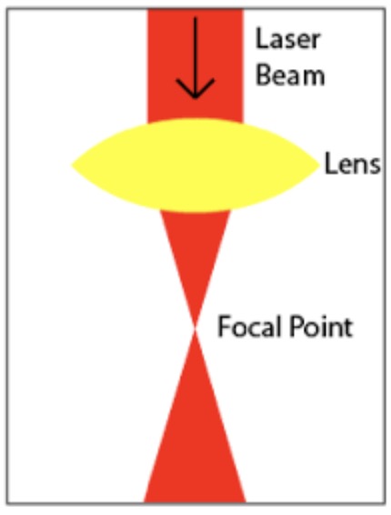
The laser beam is reflected off of mirrors to focus at a single point. The beam is wider both before and after the focal point, forming an hourglass shape, seen in the picture below.
I googled how to find this point, and a quick survey of the results suggested that there are two basic methods to find the focal point.
The first involves increasing the laser head by increments of 1mm, and carving a line with the laser after each adjustment. However, such a test requires a tool which allows you to precisely measure the distance between the head and the material. Something like the one seen in this video from BRM:
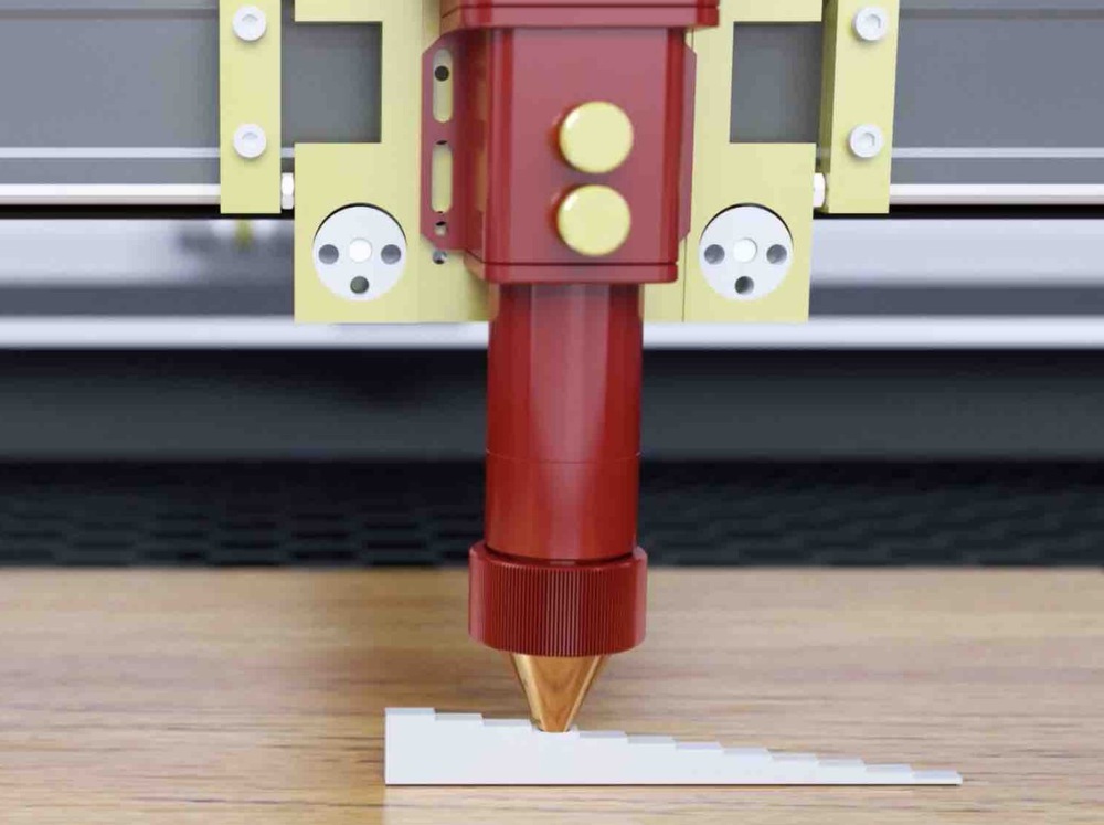
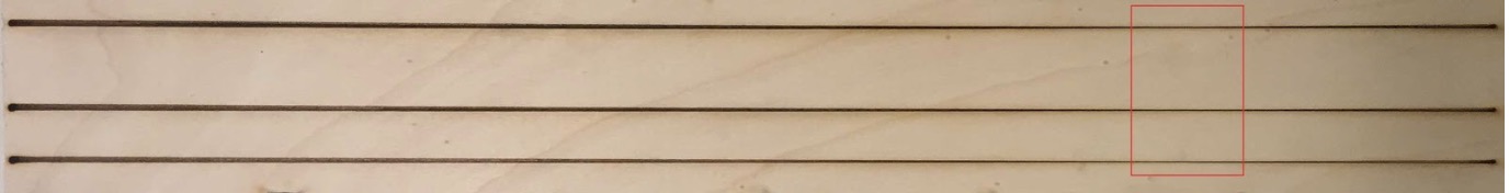
Other guides that used this method had similar measuring tools, with a different individual block for each mm increment. We had no measuring tools with this capability at Waag, so we had to go with the second method. For this method, a ramp needs to be created in the laser cutter. The laser should then be set to draw a line across the length of this ramp. This line will vary in thickness, and the point at which the line is the thinnest is the point at which the laser is at the ideal distance from the material’s surface.
Here is an example instructional video of the method.
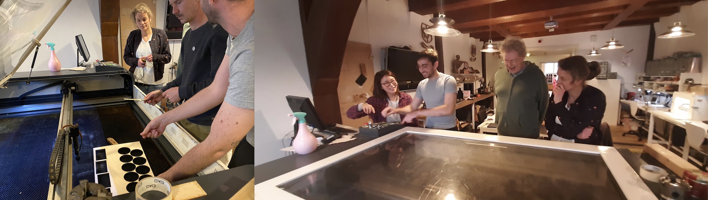
We set up our ramp using a piece of scrap wood, and propped it up on some other pieces of wood found around the lab. At its highest point, the ramp measured 27mm in height. We decided to draw three lines down the length of the ramp, all at speed 30, and at power settings of 20, 30, and 50, with the laser cutter set to ‘Cut.’
We set the laser head to 4mm distance from the ramp at its highest point, and had it draw lines of 48cm (the wood was 49cm).
The lines were the thinnest in the range of 9-13cm down the ramp.
I had to relearn some algebra in order to find what this meant the focus distance was. While the highest point was 27mm, the point 480mm down the ramp was not at a height of 0, but about 4mm, or the height of the wood at the lowest point of the ramp.
This means I first had to characterize the triangle created by this ramp, I then used that triangle to solve the distance between the surface and laser head at the point where the line was most thin. I calculated using 11cm as the distance the laser had traveled before reaching optimum focus, as it falls in the middle of our range of 9-13cm. The math I used is pictured below:
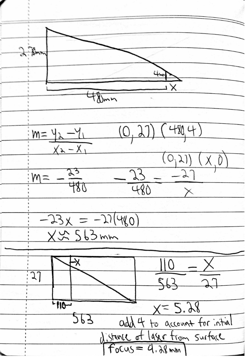
If we account for the entire range on the lines that the laser was in focus, this means ideal focus distance is between 8.3mm and 10.3mm.
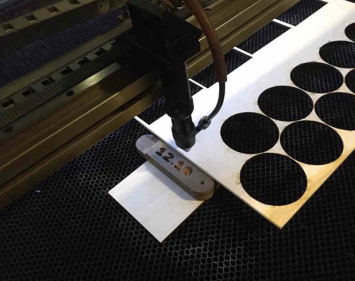
We also used a bit more crude method. Before removing the ramp from the laser cutter, we moved the head back over the thinnest point of the line, and Harm attempted to measure the distance between the head and the wood using digital calipers. This measurement was 11.6mm.
The tool Waag uses to set focus distance places the head 12.10mm away from the material. We will test our results against this number soon and see which is more accurate.
Speed, power and kerf
The kerf is the width of material that is removed by a cutting process. The speed parameter describes the movement of the laser head. The power parameter describes the output is the output power of the laser. The offset is the amount of distance by which something is out of line.
The idea
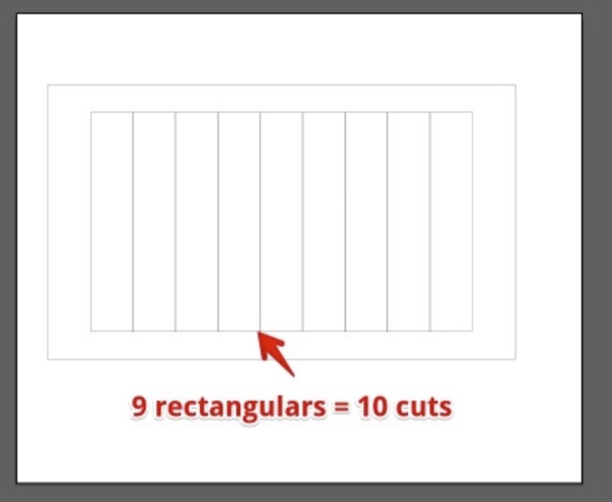
To characterize speed, power and kerf we looked at the Waag's Class of 2019 how they did that. Rutger was our mentor for the day and we looked specifically at his documentation. We took their idea of measuring the kerf at different speeds and power settings by creating a design of a horizontal rectangle divided in 10 vertical rectangles. The horizontal rectangle is 100 mm wide. The laser cutter will cut out 10 vertical lines to create the inner rectangles. When you measure the width of the combined 10 rectangles after the cut, the sum total will be less than 100 mm. The negative difference divided by 10 will be the diameter of the kerf. For instance: If, after the cut, the width of the 10 vertical rectangles combined is 96,35 mm, you can conclude that the cutter took away 3,65 mm of material. Since you made 10 lines, you divide by 10 to get the diameter of a single cut line: 0,365. When you divide this by 2 you'll know the offset. This is the number you add to your design in order for the cutter to make the true measurement of 100 mm.
The process
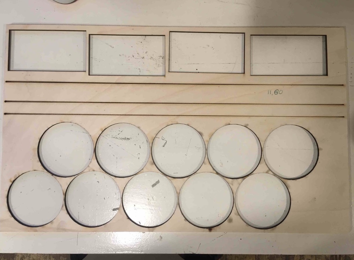
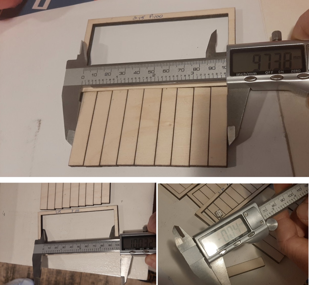
Harm made an .ai file containing the design of the rectangles. We then cut 4 instances at different speeds and power parameters. The result is a table with the kerf and offset of our laser cutter for different speeds and power parameters. We used wood of 4 mm. You can do this test again for other materials.
The laser went over the inner lines two times. So this would make the kerf bigger. The laser went over two times because I made the lines in illustrator with rectangles. The sides overlapped.
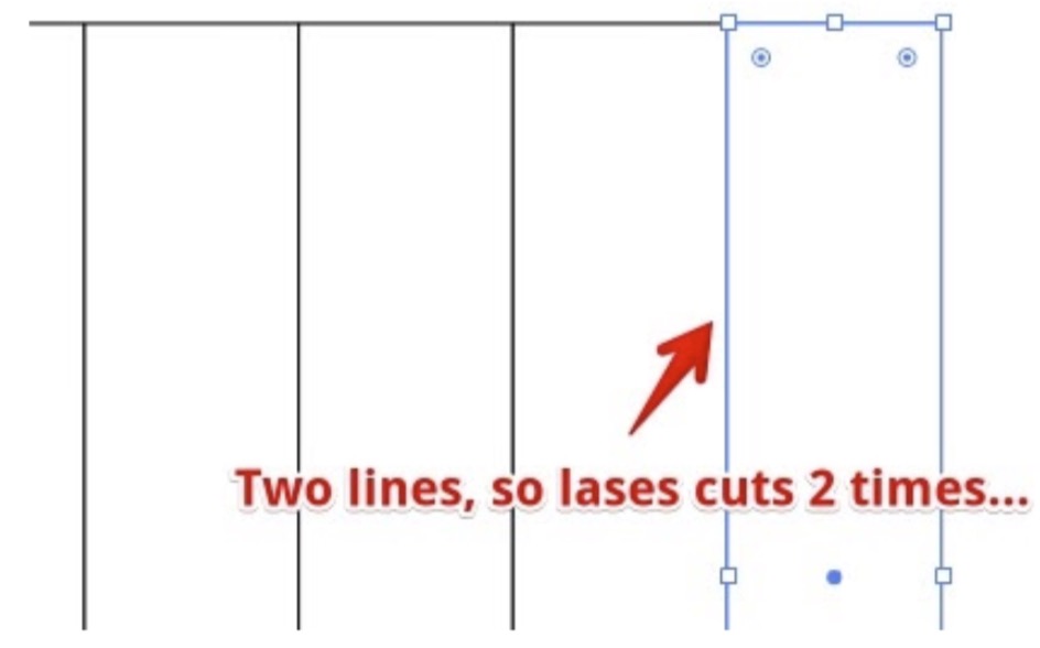
I created a new file and we tested this laser. Now it went over the lines just once.
Measure the kerf
Try to keep the cutted triangles and the caliper horizontal. Don't forget to zero the caliper (slide it back and press the ‘Zero button)
| total size(mm) | speed | power | total after cut(mm) | result(mm) | number of lines | kerf(mm) | offset(mm) |
|---|---|---|---|---|---|---|---|
| 100 | 15 | 50 | 97.51 | 2.49 | 10 | 0.249 | 0.1245 |
| 100 | 15 | 100 | 96.35 | 3.65 | 10 | 0.365 | 0.1825 |
| 100 | 30 | 50 | 98.63 | 1.37 | 10 | 0.137 | 0.0685 |
| 100 | 30 | 100 | 97.68 | 2.32 | 10 | 0.232 | 0.116 |
Rate
The laser doesn't actually cut a line. Rather it burns a series of little piercings. The rate parameter determines how far apart these holes are spaced. A high rate places them close to each other to the point where they overlap. A low rate places them further apart. We were not able to test this parameter as the rate of our laser cutter is fixed. Not physically but by degree. One shall not mess with the rate parameter.
Joint clearance
Joint clearance is the distance between mating surfaces of a joint.
How we did
The thickness of the cardboard box we used was 2.8cm. The kerf we got from the previous test was 0.137cm. We subtracted the kerf from the each number on the left side of the photo below.
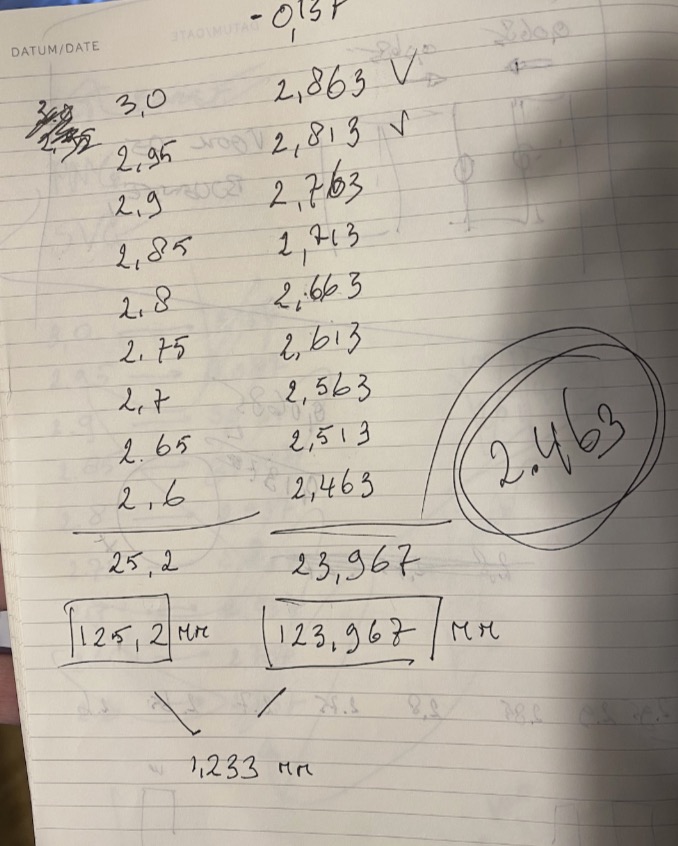
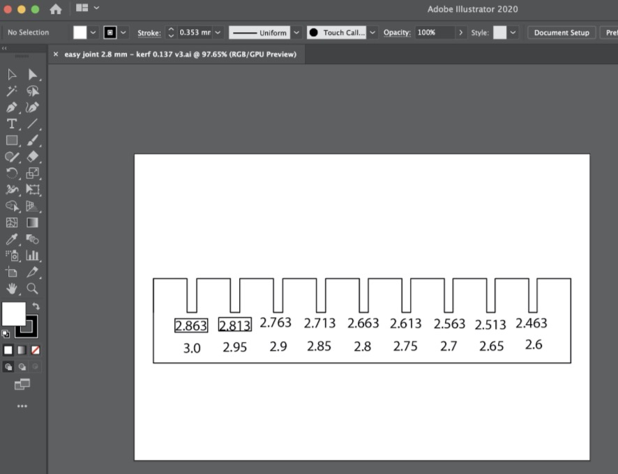
The original comb design has the numbers on it as you can see the photo below. But we didn’t know how to convert text into a vector graphic at that time. So we handwrote the numbers on the combs.
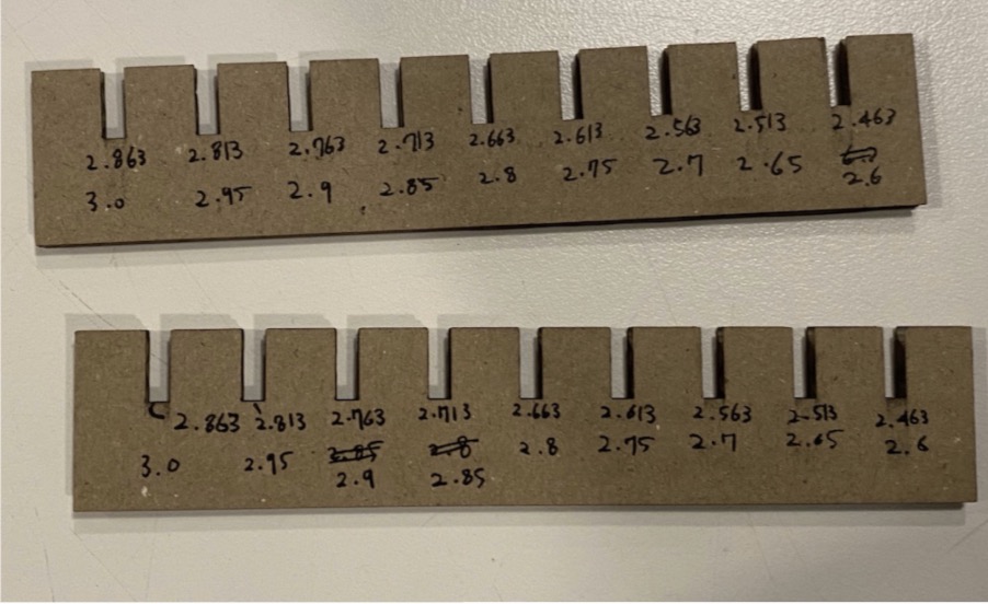
We tested which slot has the tightest fit. The 2.7 slot was too loose, but the 2.65 one made a pretty good grip together. The best one was the 2.6 one. When we first fitted them together, it felt a little bit too tight. But after taking them apart and putting them together several times, they fitted perfectly.
What went wrong
Almost all of us made the mistake of not putting on the exhaust machine when we started cutting for the first time. Most of us also opened the lid of the cutter with one hand. It then bends out of shape and lands on the sides with a loud clang. Henk commented: 'you can all of you make this mistake one time. Because the noise makes me jump out of my skin.' A mistake was made with the kerf table. We had to try different speed and power settings. The same settings were repeated twice in the table. Resulting in us doing one setting twice.
When making the ten rectangles for the kerf test, there were two lines in the design. This made the laser cutter go over the lines twice. Not really handy when you are doing a kerf test :).
Also, when we(Hyejin & Rinke) imported the comb design .ai file to the laser cutter software, we didn't convert the numbers into vector graphics. So the numbers didn't show up on the software, but we both didn't know how to convert a text into a vector graphic. We hand wrote those numbers after cutting the design with the machine. Also, we forgot to change the rectangles in which the numbers were written into the engrave mode. After a lot of trial and error, we managed to print out nice looking combs for the joint clearance test.
What went well
It was the first week we did a group assignment together. It was really fun working together. For this week's group Rutger should be included too. He explanined the machines. In a single day we learned how the machines worked and were able to cooperatively get some work done on it. A very nice day.