Week 9
INPUT DEVICES
- Group assignment
- Probe an input device(s)'s analog and digital signals
- Document your work (in a group or individually)
- Individual assignment
- Measure something: add a sensor to a microcontroller board that you have designed and read it.
MESURE SPEED
My final project is a water turbine and that is why I decided to try to mesure the speed of my motor with a Hall effect sensor.
A Hall effect sensor is a device that is used to measure the magnitude of a magnetic field. Its output voltage is directly proportional to the magnetic field strength through it. Hall effect sensors are used for proximity sensing, positioning, speed detection, and current sensing applications.
Hall effect sensor
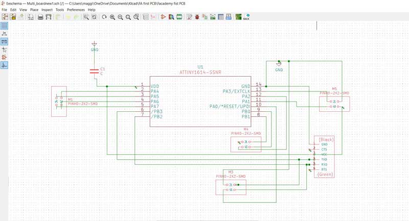
To control the Hall sensor I decided to make a new multifunctional board with ATtiny 1614 that i can connect to various components.
Here is the schematic of the ATtiny 1614 board that i made in Kicad
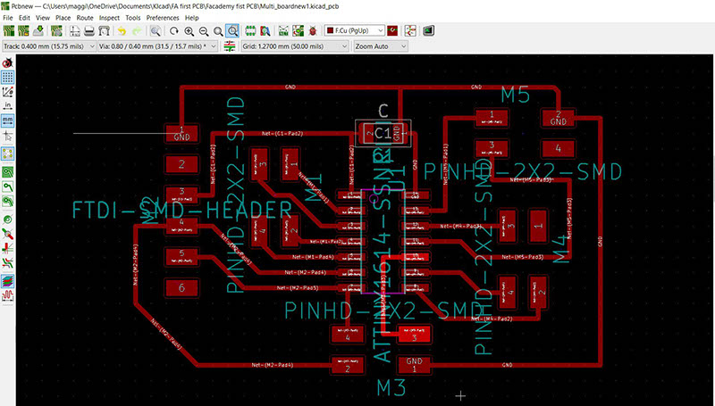
Managed to route my board with out any complications
Exported my board as a SVG file and opened it in Inscape. Tweaked it and exported to PNG format for Fab Modules
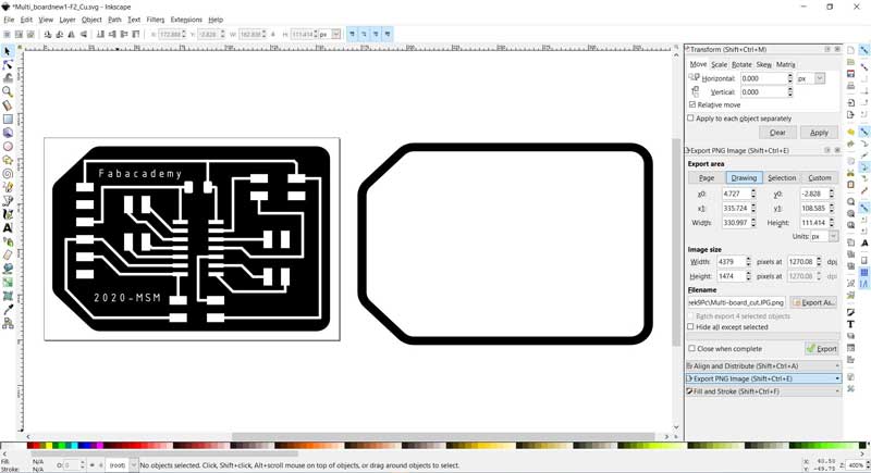
Here below are the files that I made in Kicad and milled out on the Roland SRM-20
Multi-board_traces.3dm / / Multi-board_cut.3dm
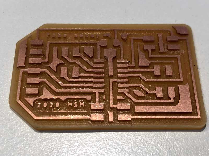
Here is the finished board after milling on the Roland SRM-20
Started soldering the components to my my board
Here is the Multi board finished

I will also make a input device board with a hall effect sensor and connect it to my new multifunctional board
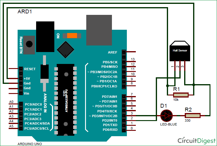
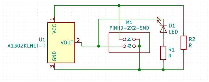
Found this Arduino schematic of a Hall effect setup that will help me to make my input device board
I managed to get my hands on a A1302KLHLT-T LH SOT 23W Hall effect sensor. Here is the data sheet
From the data sheet we can see how to correctly connect it to the ATtiny 1614 board
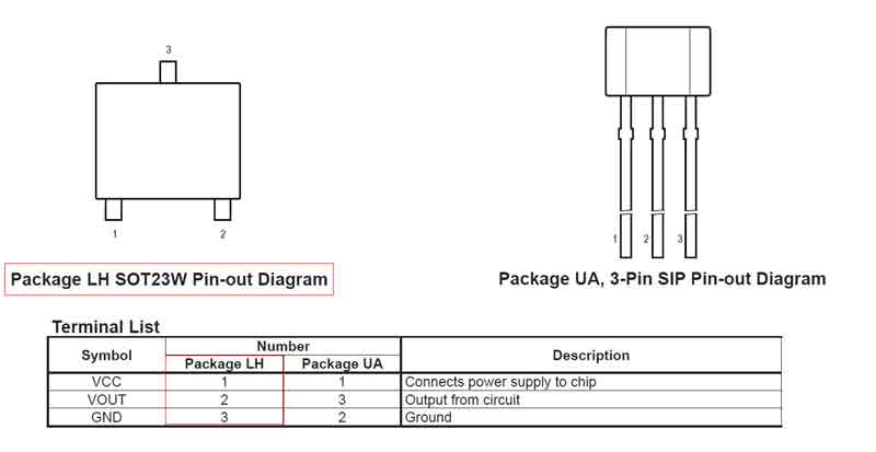
The hall effect, in short, is a relationship between electric and magnetic fields through a semiconductor that allows electricity to flow when a magnetic field is applied within the vicinity of a given hall sensor. In our case, we will be using the SOT 23W Hall effect sensor, which is a unipolar sensor. Unipolar sensors are great for scenarios where only one pole of magnet is needed. This allows us to stick a magnet to a moving object and as it cycles through its rotation, each time it passes the hall sensor, the hall sensor registers its passing and we can say that one period has been completed.
Kicad schematic of the Hall effect sensor board
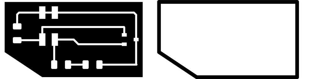
Here is the Hall affect after I exported it from Inkscape. Files read to be cut out in the Roland SRM-20
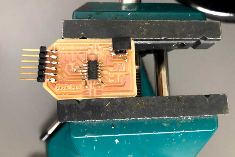
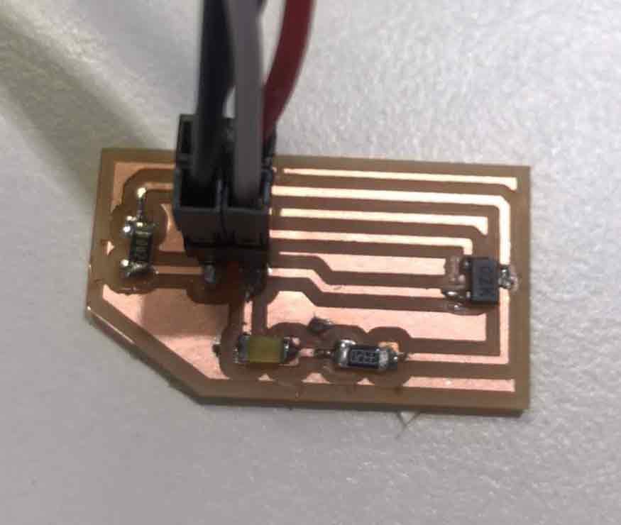
Finished soldering and connecting my Hall Affect sensor board. .
I will use this Arduino code to make the led blink when magnet passes the Hall effect sensor and it will also give a magnetic strenght reading to the computer
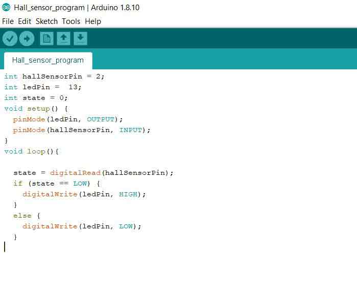
When I was connecting my sensor board I noticed that the voltage of my Hall Sensor was 3.3 volt but my board design was using 5v. To get the correct voltage i connected to the 3.3 v output on my Ardoino board.
The moment of truth will it work!!!! Will the light turn on when the magnet approaches
It worked !!! I have never been so happy to see a light turn on...
When I bring the magnet close to the sensor I get a High number of almost 600. When the magnet is far away the reading is about 300 and if I flip the magnet around and bring it close to the sensor the reading is somewhere around 30
Mesure RPM
Next step is to try to sense the speed of a computer fan that has a magnet attaced to one of the blades
The unipolar hall sensor can function as a tachometer. I will demonstrated a simple experiment using a 5V blower fan, hall sensor, and neodymium magnet attached to the fan. The setup allowed us to print out values for the approximate RPM of the fan, which can give us a more accurate idea of the flow rate of the fan.
Here is the code that i will use that i got from this website
https://makersportal.com/blog/2018/10/3/arduino-tachometer-using-a-hall-effect-sensor-to-measure-rotations-from-a-fan// digital pin 2 is the hall pin int hall_pin = 2; // set number of hall trips for RPM reading (higher improves accuracy) float hall_thresh = 100.0; void setup() { // initialize serial communication at 9600 bits per second: Serial.begin(115200); // make the hall pin an input: pinMode(hall_pin, INPUT); } // the loop routine runs over and over again forever: void loop() { // preallocate values for tach float hall_count = 1.0; float start = micros(); bool on_state = false; // counting number of times the hall sensor is tripped // but without double counting during the same trip while(true){ if (digitalRead(hall_pin)==0){ if (on_state==false){ on_state = true; hall_count+=1.0; } } else{ on_state = false; } if (hall_count>=hall_thresh){ break; } } // print information about Time and RPM float end_time = micros(); float time_passed = ((end_time-start)/1000000.0); Serial.print("Time Passed: "); Serial.print(time_passed); Serial.println("s"); float rpm_val = (hall_count/time_passed)*60.0; Serial.print(rpm_val); Serial.println(" RPM"); delay(1); // delay in between reads for stability }
Magnús St. Magnússon © 2020| v1
Madefor FabAcademy