Week 4
Electronics Production

Week 4 - Assignments
• What is the FabISP?
• Genealogy
• Download the Board Files and Mill the Board
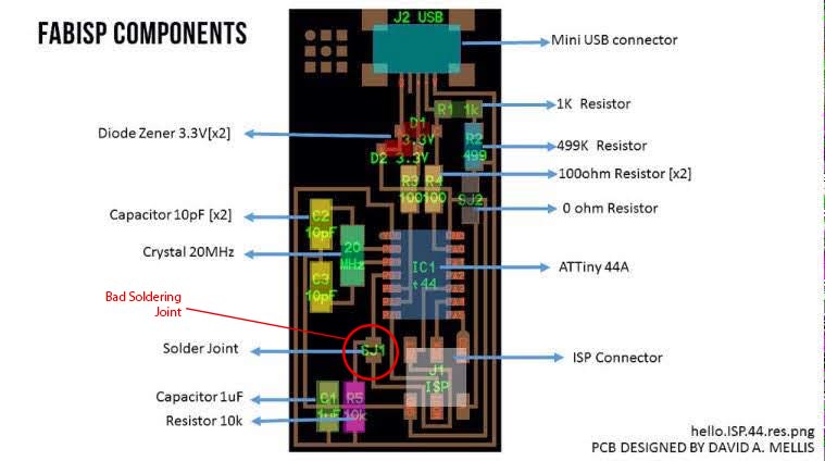
• Components
• "Smoke Test"
• Troubleshooting Short Circuits
• Install Necessary Software for AVR Programming
• Power the FabISP Board
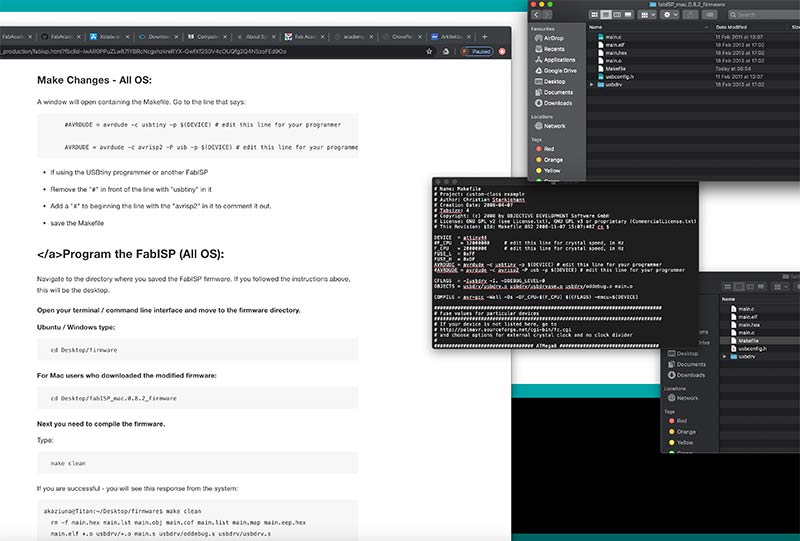
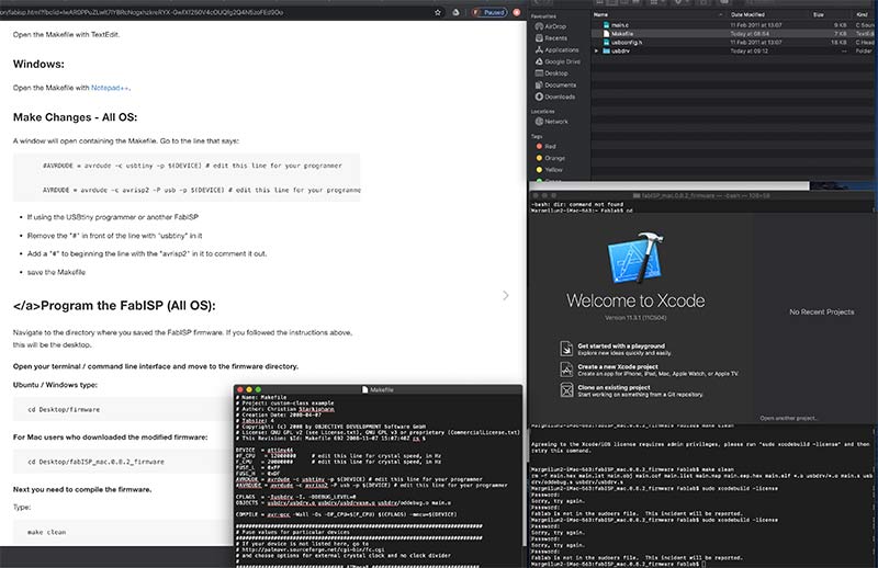
• Edit the Makefile
• Program the FabISP (All OS)
• After You Have Programmed the Board
What is the FabISP
The FabISP is an in-system programmer for AVR microcontrollers, designed for production within a FabLab. It allows you to program the microcontrollers on other boards you make.
The Electronics Production assignment is to mill the board, stuff it with components and program it. We will be using these programmers through the semester to program the other boards we create.
• This one uses a mini Usb connector to make durable
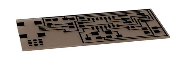 FabISP
Download the Board Files and Mill the Board
Roland SRM-20
Circuit Board Traces
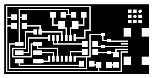 Download the traces png.
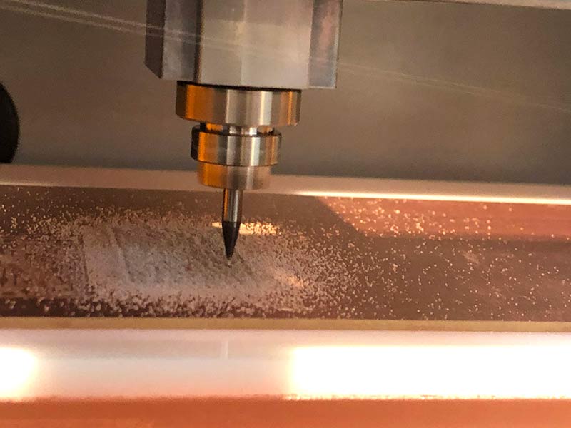
Mill using the fab modules and a 1/64" bit.
 Download the outline png.
Mill using the fab modules and a 1/32" bit.
Roland SRM-20 is the machine that we have in our lab to mill out the boards
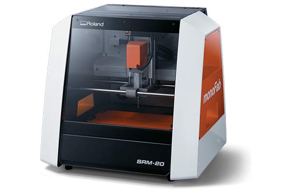
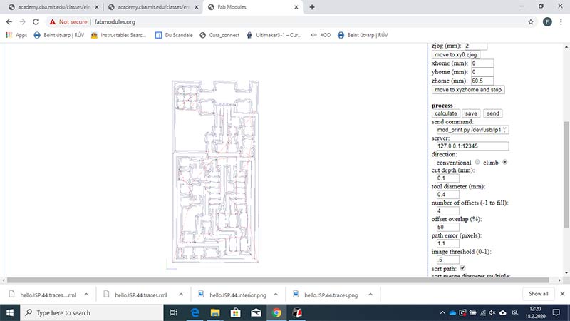
To make files that the machine can use we have to convert the images to RML format
We can use this website to make the files.
www.fabmodules.org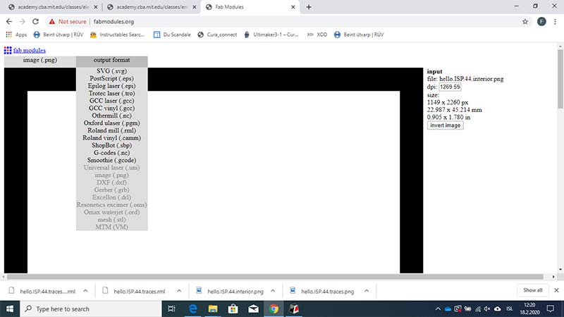
Import the PNG image of the board and the website will convert it to a usable RML file.
Do this with both files
Now we can load the RML files in to the Roland control program
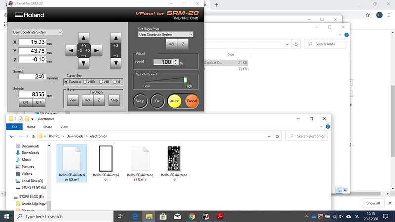
Then we have to sett the x/y and Z possition
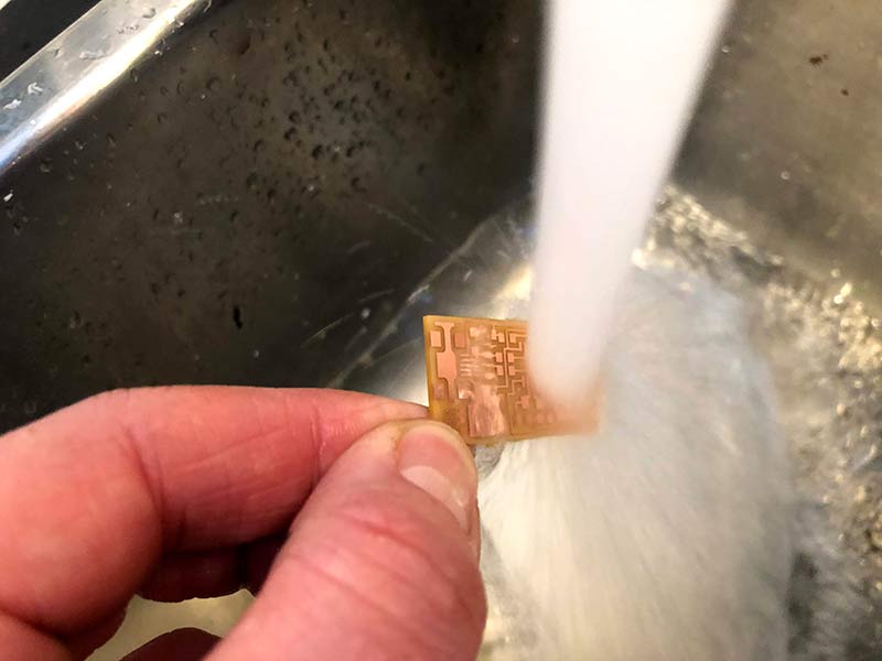
When the milling is finished we can clean it and start the soldering process
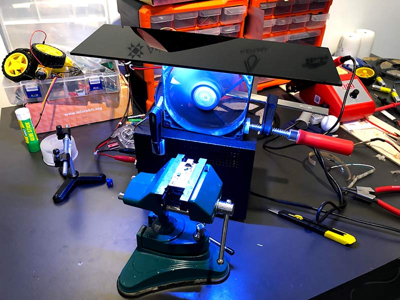
Because I did not hava a good setup for making PCB I made one with materials laying around in the lab
I had a old computer laying around and took out the fan and attached it to the power supply for ventilation
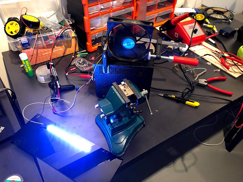
Then I took a led strip and attached it to a black plexi glass i found laying around and connected it to the power supply
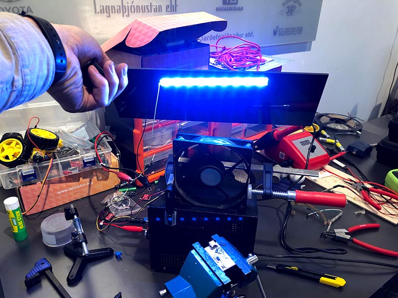
Vola.. Ventilation and a good light for soldering small parts.
Ready for Soldering
Soldering

Soldering
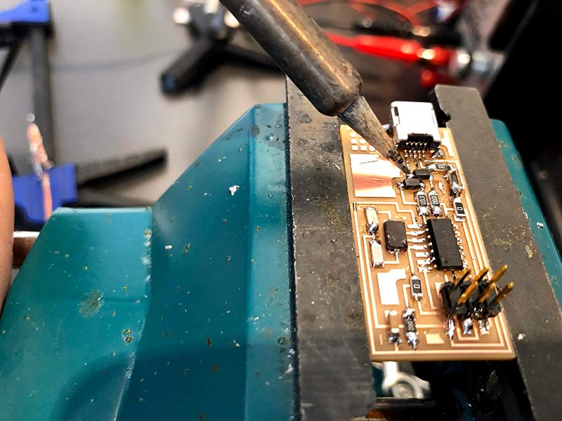
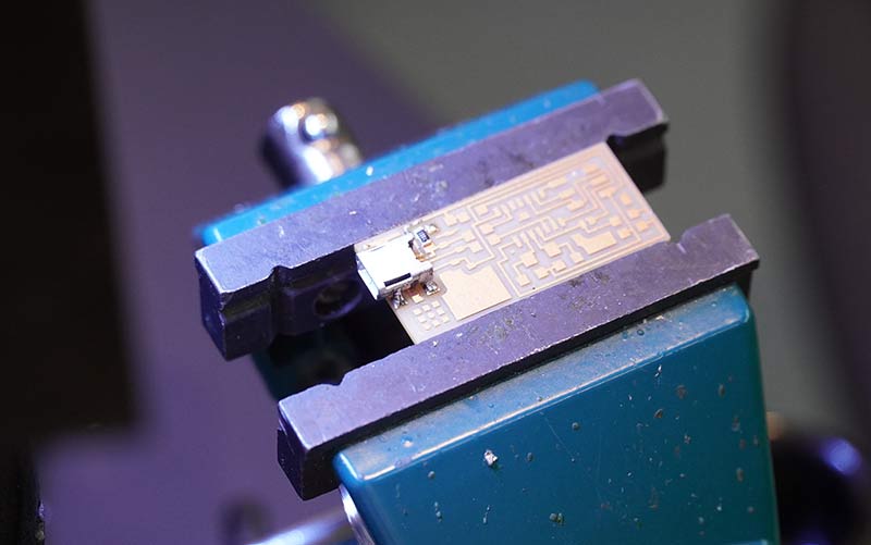
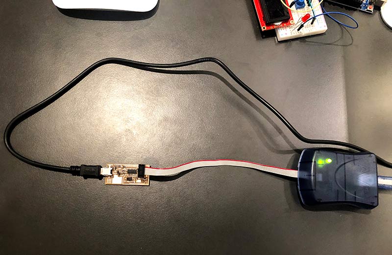
Testing the PCB
I checked the board for errors

Everything looked good but i got a Red ligt on my AVR connection
The red light is a indication of a bad connection
I found out that i had no connection on the board that is marked in red in the picture
When that was fixed I got a green light on the AVR connector.
PCB Programing
When talking about programing the AVR i had lot of issues. I started out downloading Ubuntu for a old computer that i desided to use for programing
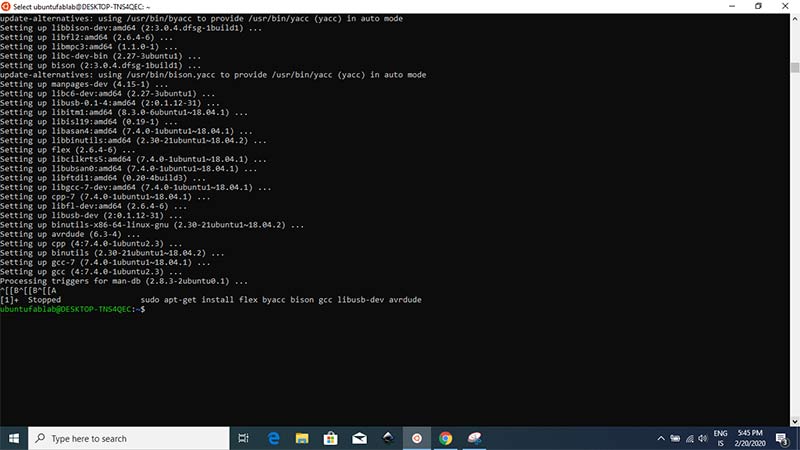
I followed the istructions and installed AVR and the firmware
After many failed attemts we found out that the windows opertating system and the drivers on my computer was to new and was not able to connect to the board
So we decided to try the Mac that i have in the lab


We followed the Mac Os istructions.
After many failed attemts found out that the new Catalina os x is not supporting 32 bit programs any more
Magnús St. Magnússon © 2020| v1
Madefor FabAcademy