Final Project
The portable water turbine
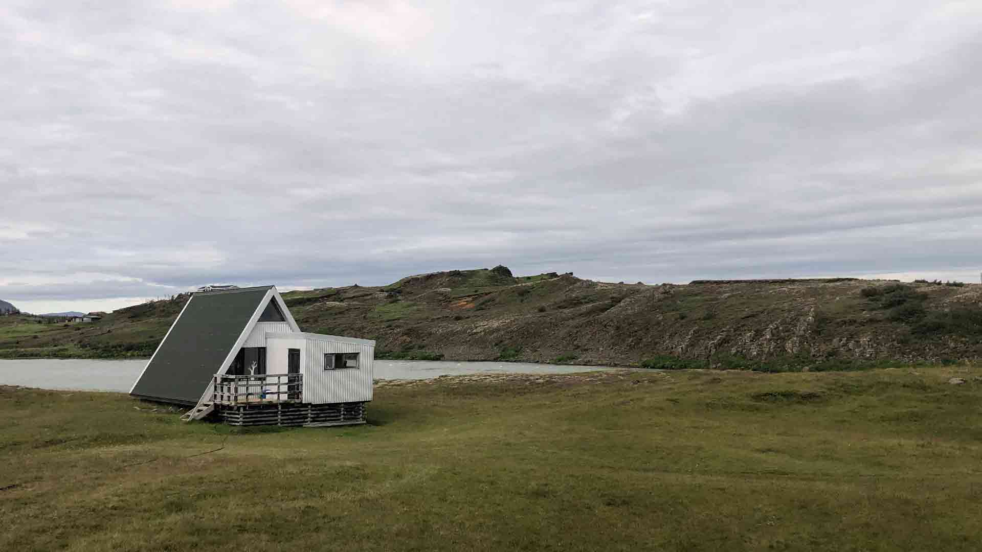
I have a little fishing hut by a river in a rural part of south Iceland. This hut is quite primitive with no running water and almost no electricity. When I say almost, its because I have solar cells on the rooftop to engine a few lights to help over the darkest hour. As for other equipment, I have a gas stove to cook and a gas heater to keep warm and prevent the hut from molding. Some might say that this hut is to primitive to use but for me its quite the opposite. Sometimes the only therapy you need is to get away from the hectic everyday life and experience the peace and quiet, and that is what I get in my hut.
That said, of course here are some aspect of my hut that I would like to adjust. The solar cell for example does not function as it could due to scars sunlight in the winter time in Iceland. That, combined with the long dark days, makes it hard to rely on solely.
Like I said before, the hut is situated by a river. In Iceland we have a long history of harvesting rivers and streams for electricity. Iceland gets about 71% of its electricity this way and another 22% from geothermal harvesting. These facts are part of the Icelandic culture and shape the way we think about our nature. Therefore, it was a natural step to try to harvest the river by my hut to make my own electricity with some kind of a water turbine.
But I didn’t want to stop there. As much as I love my hut, I also enjoy traveling through the wilderness of Iceland, by cars, horses and on my feet. And as much as I enjoy the peace and quiet, I also know that the weather in Iceland can change rapidly and you should always have a fully charged phone or an emergency locator of any kind. This, as well as the fact that the Icelandic wilderness is full of rivers and water streams got me to the idea to find a way to make a small, portable water turbine, efficient enough to charge a phone, a radio or similar.
ABOUT ME As a trained pilot and graphic designer working for a furniture manufacturer, I have always been fascinated by how things work. I am a craftsman by nature and have a deep need to understand “the material” and its capacity. Being married for over twenty years, a father to three kids and living in the countryside has also been the theme for most of my adult life, making me inclined to always try to find practical ways to better my surrounding for the benefit of the whole. My Fab Academy project regarding a portable water turbine originates from these elements and will hopefully benefit others as well.Final project
| Developer: | Magnus St. Magnusson |
| Category: | Electric generating device |
| Skill: | Electric, 3d design, 3d printing, CNC mill |
| Date Post: | 04 February, 2020 |
| Tags: | Electric Turbine, Electric generation |

The path to the final project
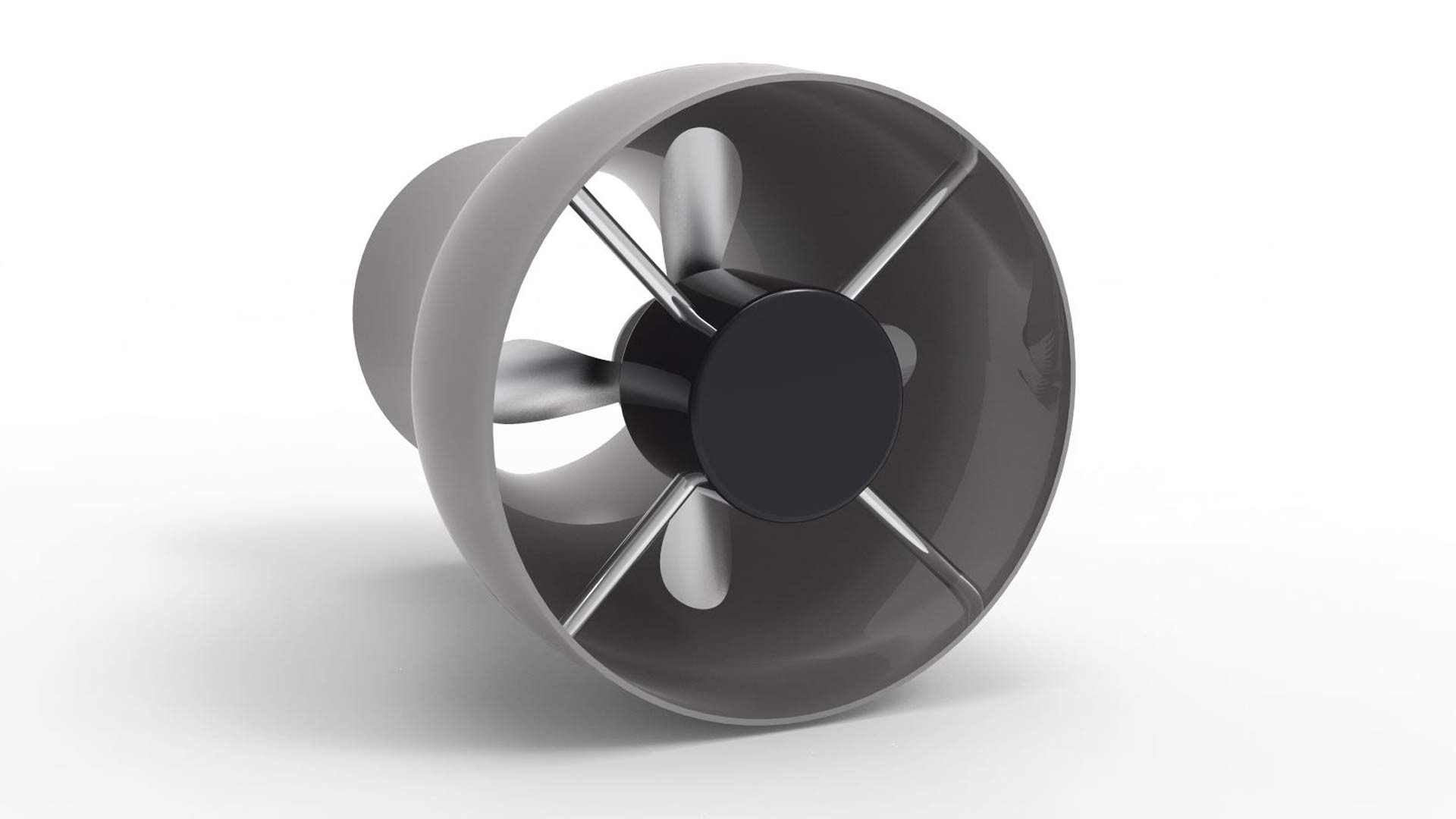
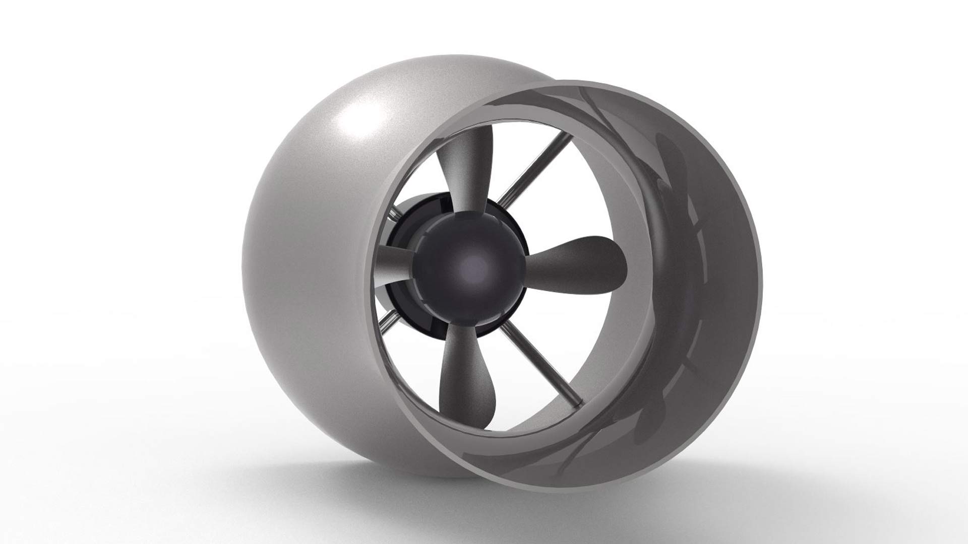
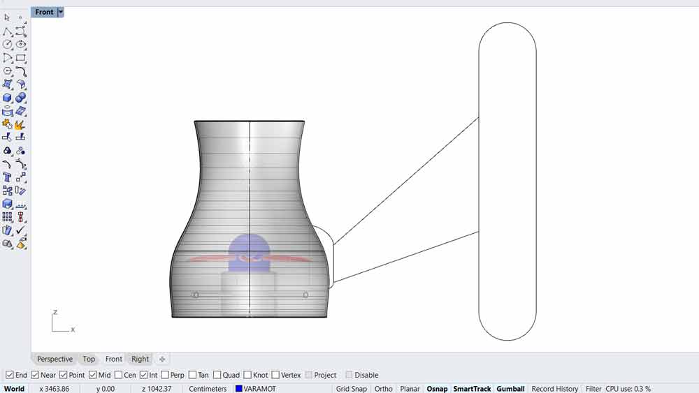
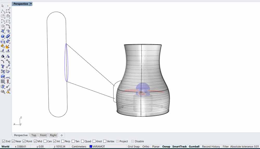
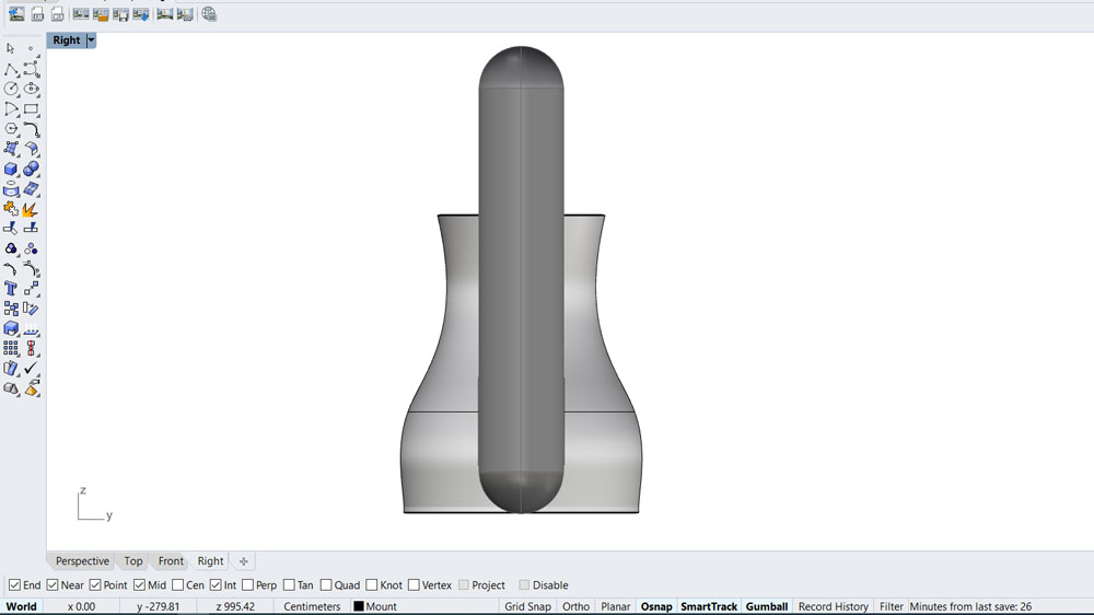
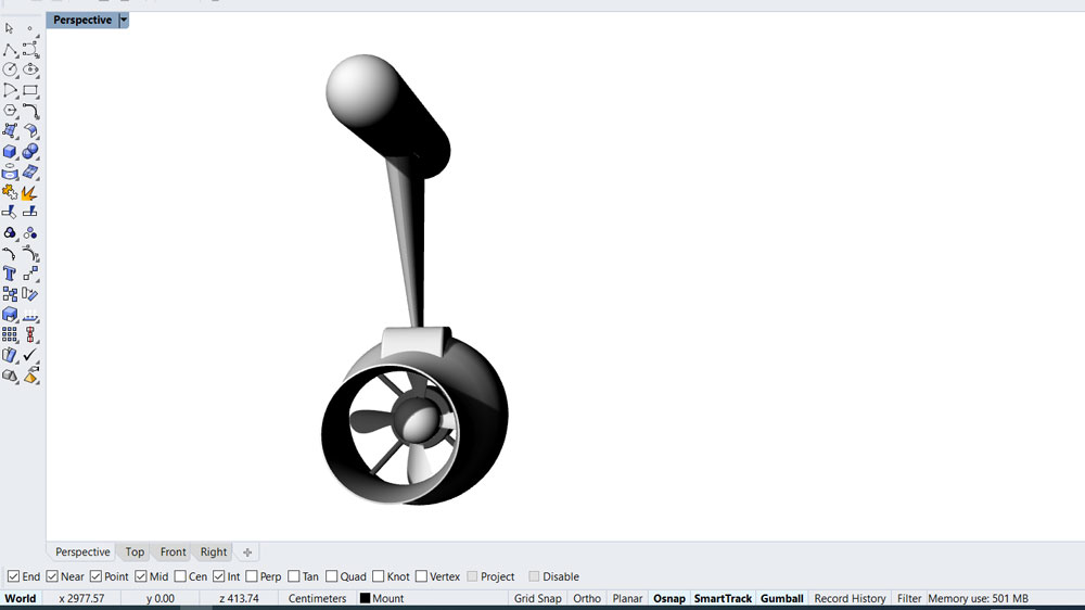
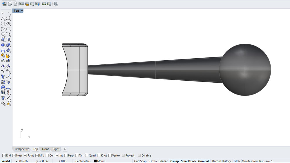
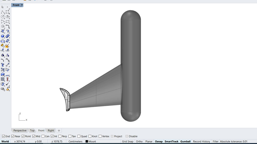
I started out by designing a 3D model of a water jet turbine
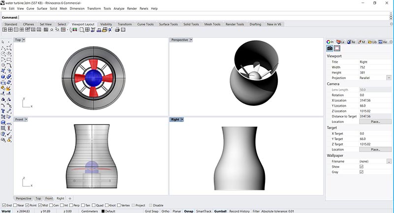
Rhino 3d file
[ water-turbine.3dm ]I made a turntable rendering to show the turbine from all sides
Click on the picture and move the mouse left and right to turn the drawing
Double click to see the water turbine in full screen
I then decided to design and make a logo for my Water turbine final project
Pressed my Water turbine logo on a T-shirt

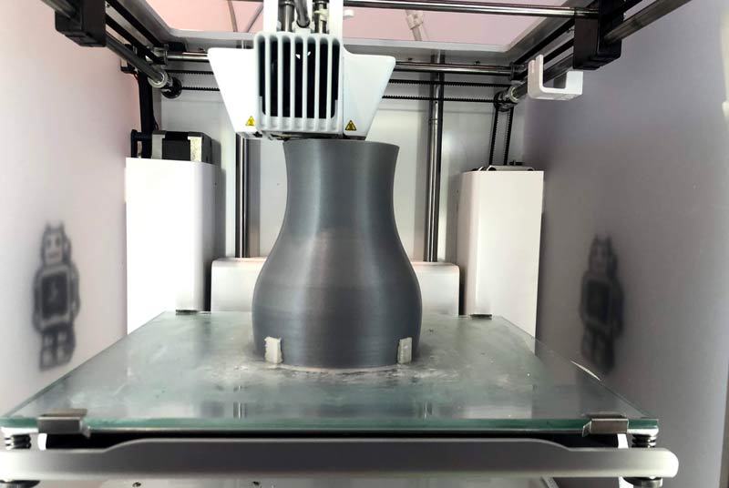
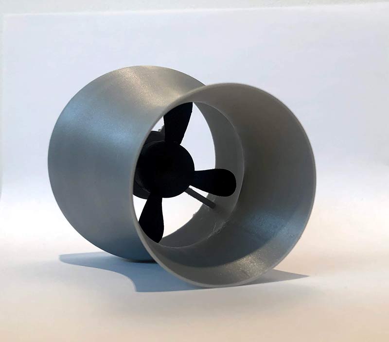
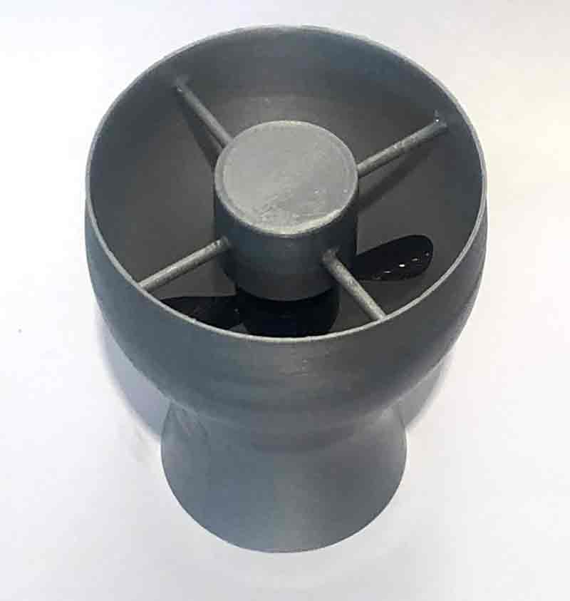
3d print of the final project
Water Jet Turbine
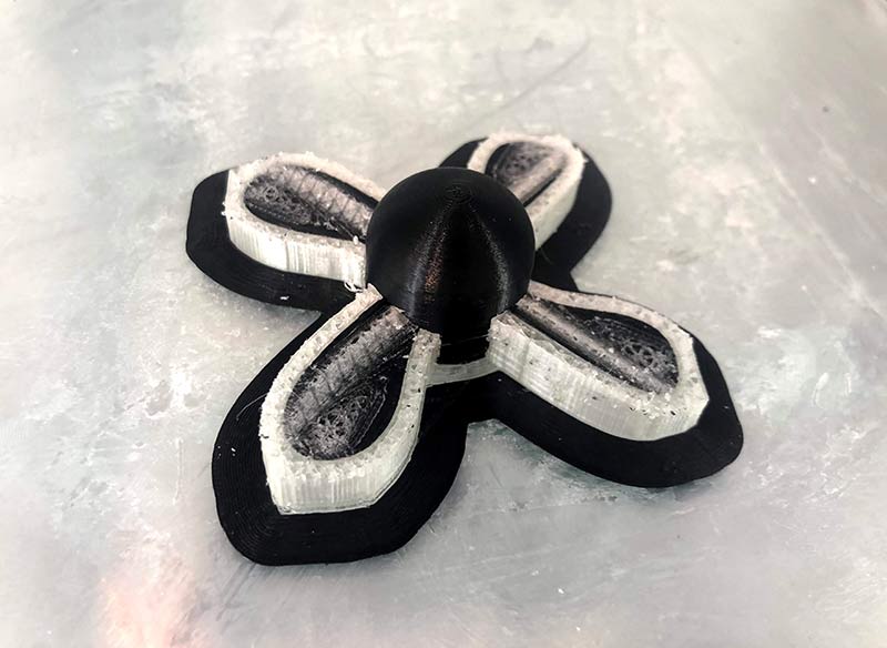
The prop was printed separatly and attached to the model
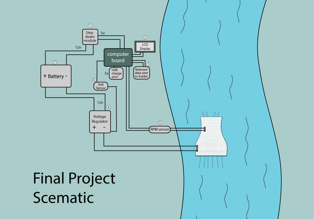
Final project schematic
Here is the schematic of the water turbine that i designed to get a overview of the components i need and how to connect them all together.
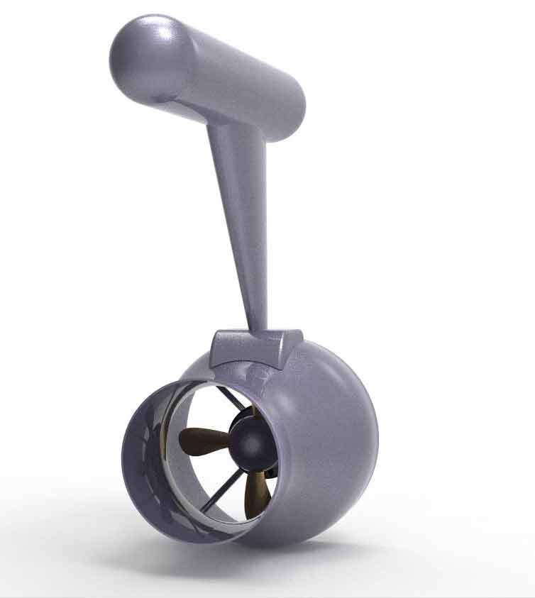
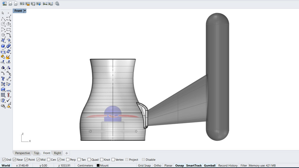
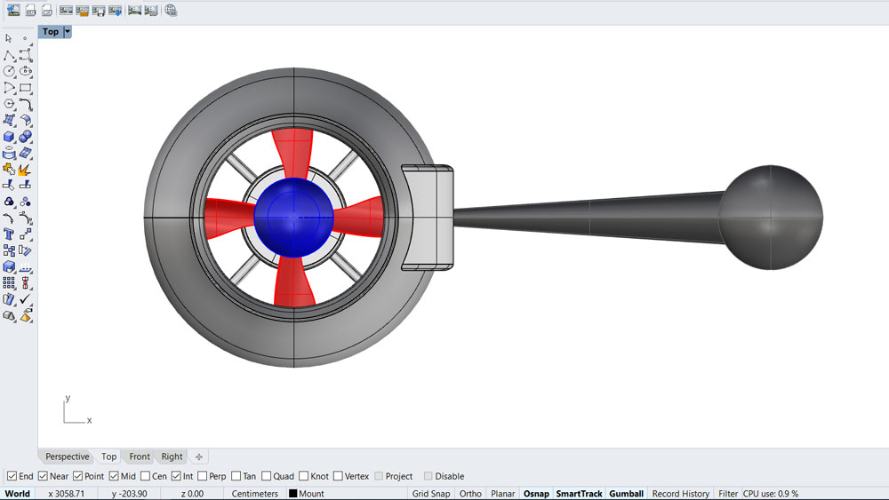
Bracket
In week 16 - Moulding and Casting I designed a pracket that will be connected to my Water Turbine
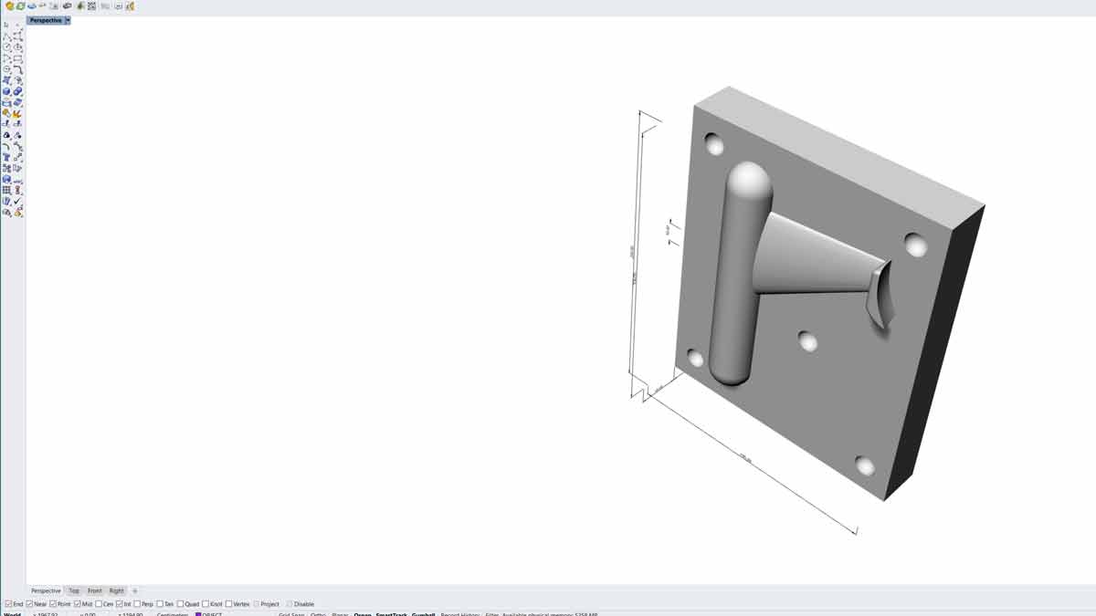
Here is a rendered image of the Water Turbine with the bracket .
Components of the project
1) Voltage stepdown
For voltage stepdown i will use Vellman VMA404 adjustable voltage step down module
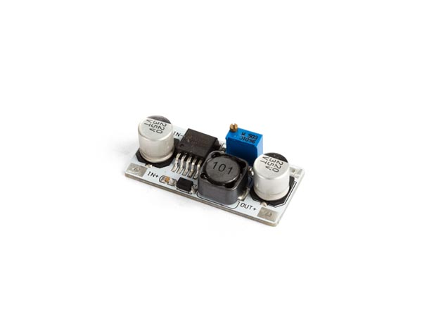
- input voltage: 3 to 40 VDC
- output voltage: 1.25 to 35 VDC
- max. output current: 2.5 A
- chip: LM2596S
- dimensions: 49 x 26 x 12 mm (1.14 x 1.02 x 0.47 " )
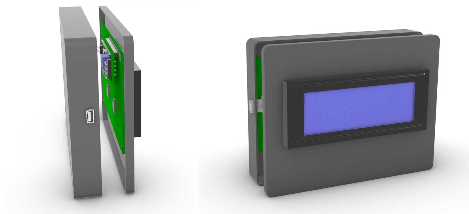
2) LCD display
My plan is to use a i2c 2004 LCD display screen for information on the charging and speed
https://www.amazon.com/SunFounder-Serial-Module-Display-Arduino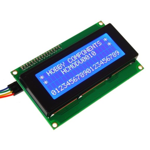
- I2C Address: 0x20-0x27(0x20 default)
- Number of Characters: 20 characters x 4 Lines
- Blue LED backlight with white char color
- Adjustable contrast
- Supply voltage: 5V
- Interface: IIC/TWI
- View direction: Wide viewing angle
- Dot size: 0.55 x 0.55 mm / Dot pitch: 0.60 x 0.60 mm
- Character size: 2.96 x 4.75 mm /Character pitch: 3.55 x 5.35 mm
- Size: 98x60x24mm
- Weight: 75g
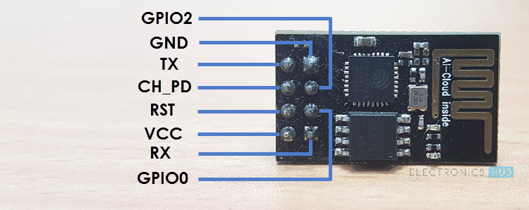
3) WiFi module
I want to be able to monitor my charging with a app on my cell phone remotely so i will use a ESP8266 WiFi module
https://www.amazon.com/dp/B01N98BTRH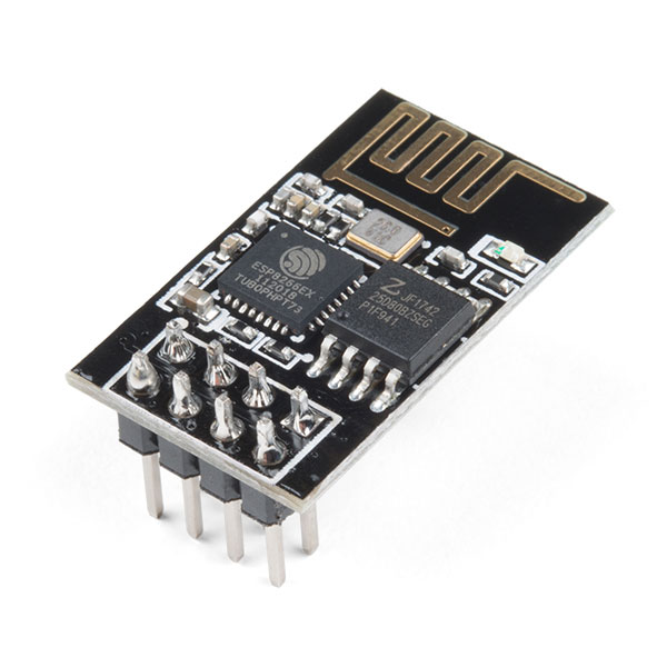
What is ESP 8266 module
ESP8266 is a wifi SOC (system on a chip) produced by Espressif Systems . It is an highly integrated chip designed to provide full internet connectivity in a small package.
ESP8266 can be used as an external Wifi module, using the standard AT Command set Firmware by connecting it to any microcontroller using the serial UART, or directly serve as a Wifi-enabled micro controller, by programming a new firmware using the provided SDK. The GPIO pins allow Analog and Digital IO, plus PWM, SPI, I2C, etc. This board has been around for almost a year now, and has been used mostly in IoT contexts, where we want to add connectivity for example to an Arduino project. A wide adoption has been facilitated by the very modest price, ranging from 2.50 to 10 USD depending on the features offered by the manufacturers.
Technical information
- 802.11 b / g / n
- Wi-Fi Direct (P2P), soft-AP
- Built-in TCP / IP protocol stack
- Built-in TR switch, balun, LNA, power amplifier and matching network
- Built-in PLL, voltage regulator and power management components
- 802.11b mode + 19.5dBm output power
- Built-in temperature sensor
- Support antenna diversity
- off leakage current is less than 10uA
- Built-in low-power 32-bit CPU: can double as an application processor
- SDIO 2.0, SPI, UART
- STBC, 1×1 MIMO, 2×1 MIMO
- A-MPDU, A-MSDU aggregation and the 0.4 Within wake
- 2ms, connect and transfer data packets
- standby power consumption of less than 1.0mW (DTIM3)
4) Charging control module
To regulate my charging i will use a charging board that keeps a constant 12V charge so my battery is protected from a variable current from the water turbine
XH-M603 Charging Control Module Digital LED Display Storage Lithium Battery Charger Control Switch Protection Board 12V

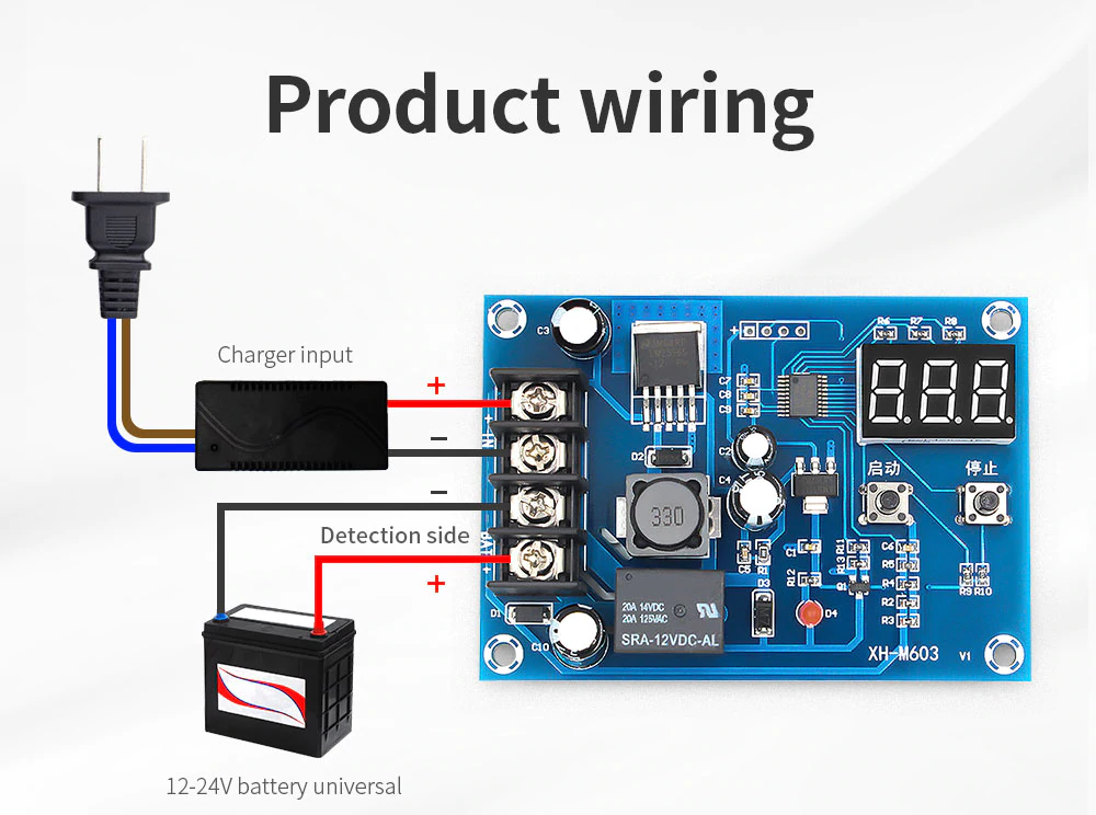
https://www.aliexpress.com/item/32946441318.html?spm=a2g0s.9042311.0.0.5bfd4c4d8RK5Gn
4) RPM sensor
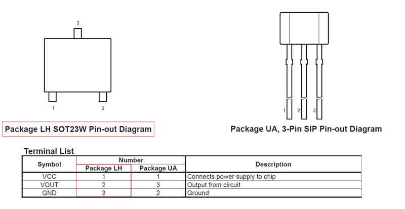
To sense the RPM of the water turbine i will use A1302KLHLT-T LH SOT 23W Hall effect sensor
The hall effect, in short, is a relationship between electric and magnetic fields through a semiconductor that allows electricity to flow when a magnetic field is applied within the vicinity of a given hall sensor. In our case, we will be using the SOT 23W Hall effect sensor, which is a unipolar sensor. Unipolar sensors are great for scenarios where only one pole of magnet is needed. This allows us to stick a magnet to a moving object and as it cycles through its rotation, each time it passes the hall sensor, the hall sensor registers its passing and we can say that one period has been completed.
In week 6 i designed a board with a Hall sensor that i connected to a Attiny 1614 board that i also made.
Packaging
I have started designing the main control box of the turbine. It will house all the electrical components and will be 3d printed
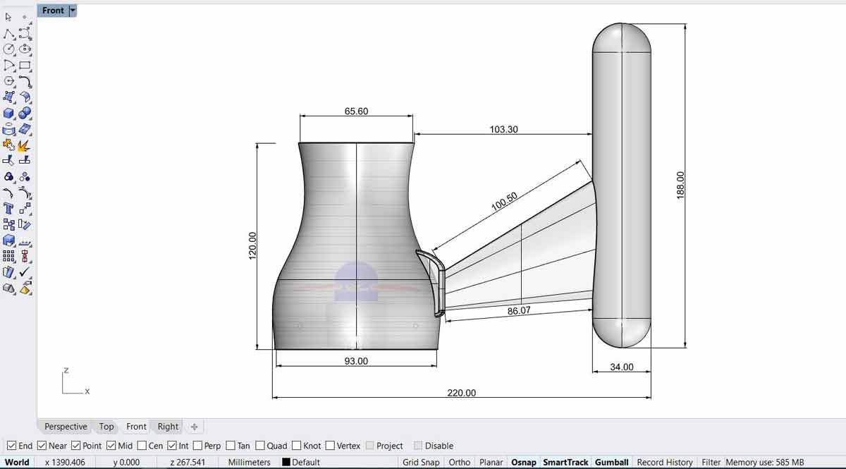
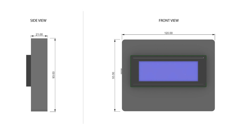
Dimensions of the the control box
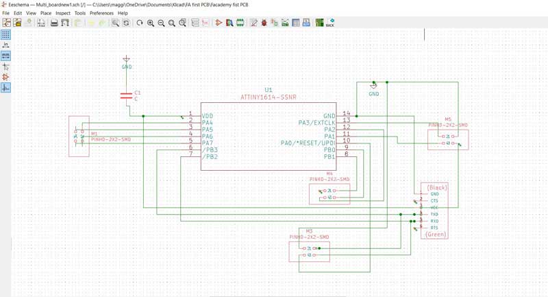
Main Control Board
The board I made to control all the elliments will be a computer board with ATtiny 1614 that i can connect to all of the input and output devices
Here is the schematic of the ATtiny 1614 board that i made in Kicad
MESURE SPEED
My final project is a water turbine and that is why I decided to try to mesure the speed of my motor with a Hall effect sensor.
A Hall effect sensor is a device that is used to measure the magnitude of a magnetic field. Its output voltage is directly proportional to the magnetic field strength through it. Hall effect sensors are used for proximity sensing, positioning, speed detection, and current sensing applications.
Hall effect sensor
I will also make a input device board with a hall sensor and connect it to my new multifunctional board
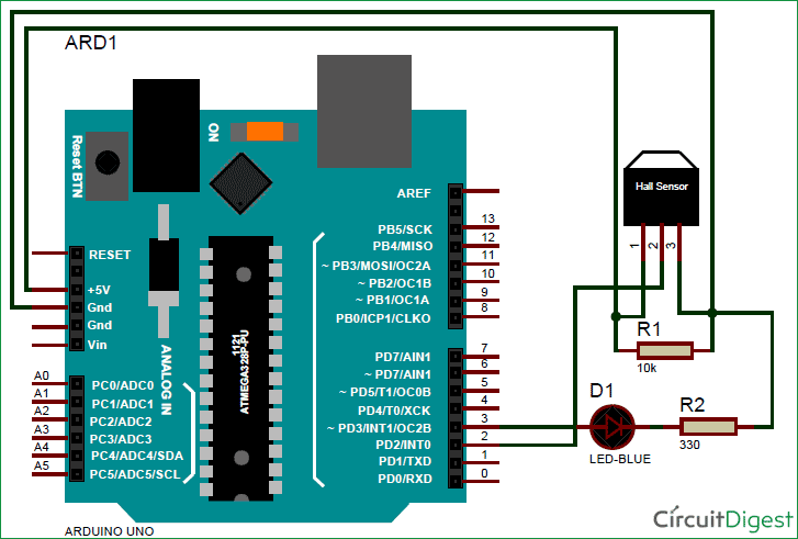
Found this Arduino schematic of a Hall affect setup that will help me to make my input device board
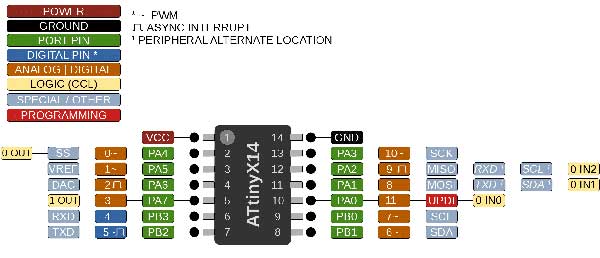
I managed to get my hands on a A1302KLHLT-T LH SOT 23W Hall affect sensor. Here is the data sheet
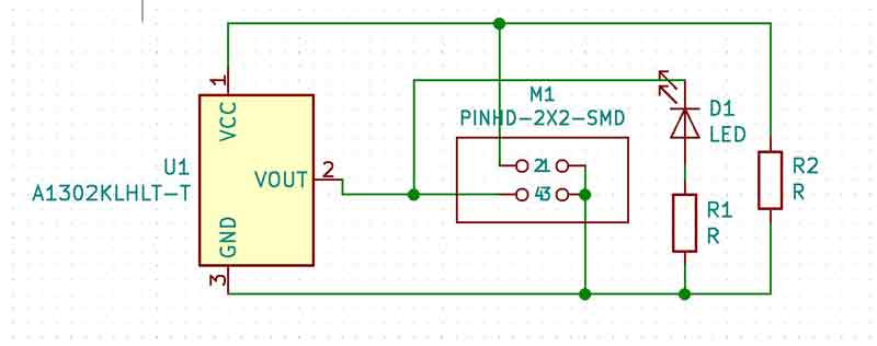
From the data sheet we can see how to correctly connect it to the ATtiny 1614 board
Kicad schematic of the Hall effect sensor board
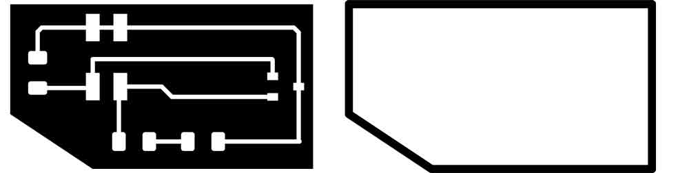
Here is the Hall affect after I exported it from Inkscape. Files read to be cut out in the Roland SRM-20
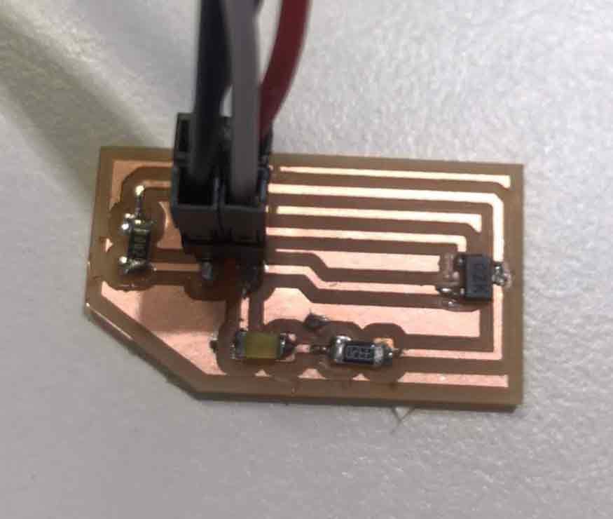
Finished soldering and connecting my Hall Affect sensor board. .
https://makersportal.com/blog/2018/10/3/arduino-tachometer-using-a-hall-effect-sensor-to-measure-rotations-from-a-fan
I will use this Arduino code to make the led blink when magnet passes the Hall effect sensor and it will also give a magnetic strenght reading to the computer
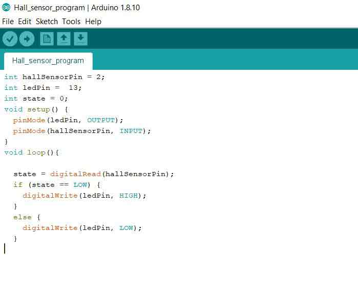
When I was connecting my sensor board I noticed that the voltage of my Hall Sensor was 3.3 volt but my board design was using 5v. To get the correct voltage i connected to the 3.3 v output on my Ardoino board.
The moment of truth will it work!!!! Will the light turn on when the magnet approaches
It worked !!! I have never been so happy to see a light turn on...
When I bring the magnet close to the sensor I get a High number of almost 600. When the magnet is far away the reading is about 300 and if I flip the magnet around and bring it close to the sensor the reading is somewhere around 30
Mesure speed
Next step is to set try to sense the speed of a computer fan that has a magnet attaced to one of the blades
The unipolar hall sensor can function as a tachometer. I will demonstrated a simple experiment using a 5V blower fan, hall sensor, and neodymium magnet attached to the fan. The setup allowed us to print out values for the approximate RPM of the fan, which can give us a more accurate idea of the flow rate of the fan.
// digital pin 2 is the hall pin
  int hall_pin = 2;
  // set number of hall trips for RPM reading (higher improves accuracy)
  float hall_thresh = 100.0;

  void setup() {
    // initialize serial communication at 9600 bits per second:
    Serial.begin(115200);
    // make the hall pin an input:
    pinMode(hall_pin, INPUT);
  }

  // the loop routine runs over and over again forever:
  void loop() {
    // preallocate values for tach
    float hall_count = 1.0;
    float start = micros();
    bool on_state = false;
    // counting number of times the hall sensor is tripped
    // but without double counting during the same trip
    while(true){
      if (digitalRead(hall_pin)==0){
        if (on_state==false){
          on_state = true;
          hall_count+=1.0;
        }
      } else{
        on_state = false;
      }

      if (hall_count>=hall_thresh){
        break;
      }
    }

    // print information about Time and RPM
    float end_time = micros();
    float time_passed = ((end_time-start)/1000000.0);
    Serial.print("Time Passed: ");
    Serial.print(time_passed);
    Serial.println("s");
    float rpm_val = (hall_count/time_passed)*60.0;
    Serial.print(rpm_val);
    Serial.println(" RPM");
    delay(1);        // delay in between reads for stability
  }
Designing the mould
For this week I wanted to design and make a moulding cast that I could use for my Final Project.
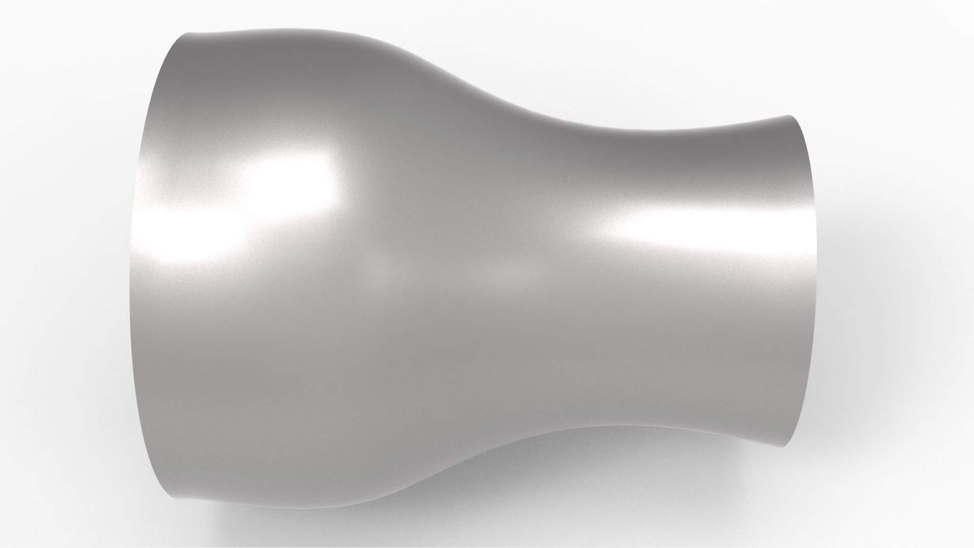
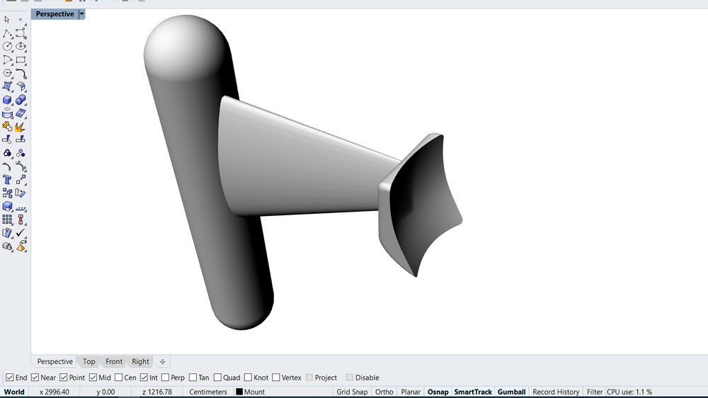
So I decided to make a mount for my Turbine. This item will stear the turbine in line with the current and make it steady under water
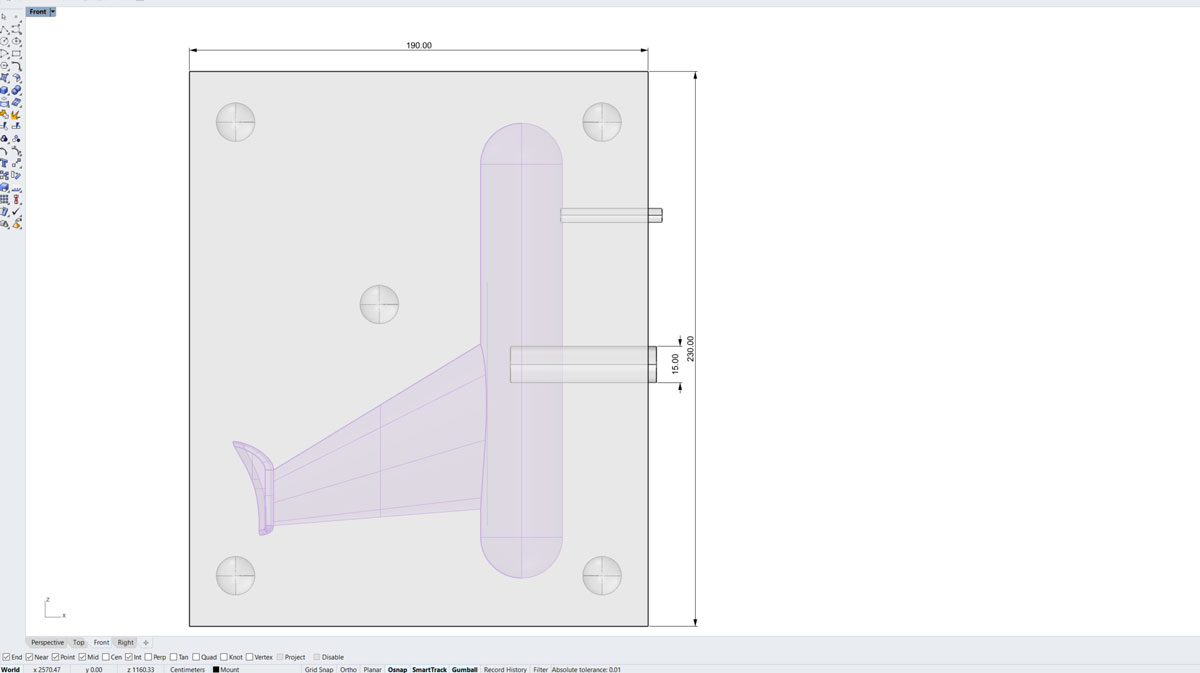
Started by drawing a wireframe of the turbine mount
After drawing the outlines and tweaking them around a bit I got the shape I was happy with and then made a 3d model from the outlines.
Making the mould
After I finished drawing the bracket that I was going to mount to my Turbine. Then the next step was to make mould around it
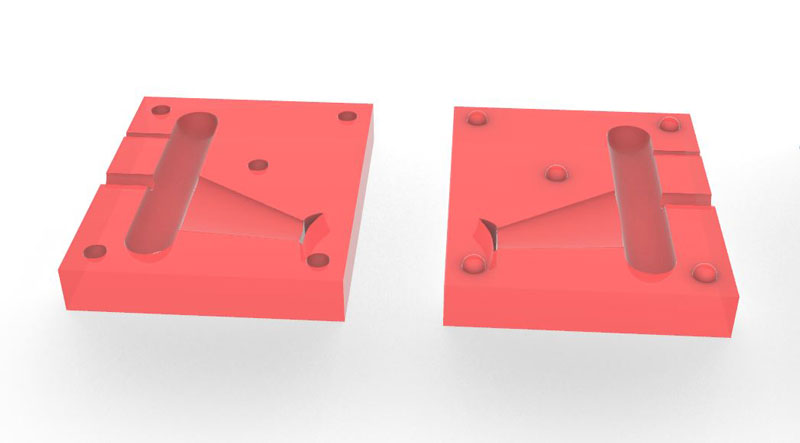
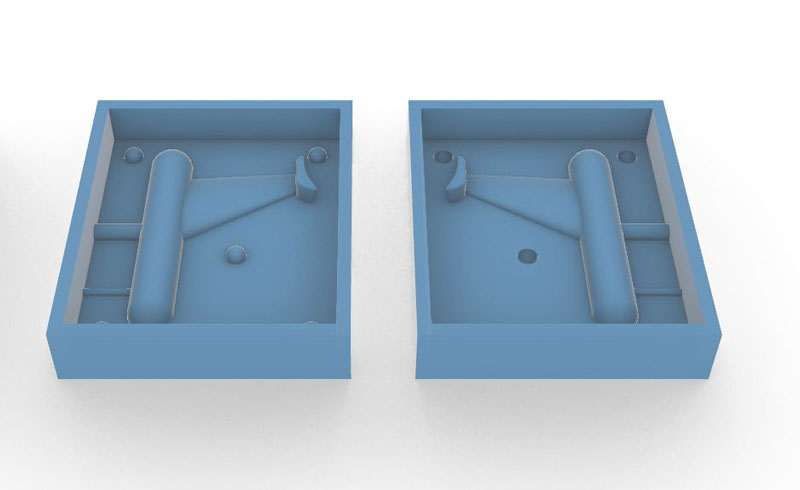
Mould
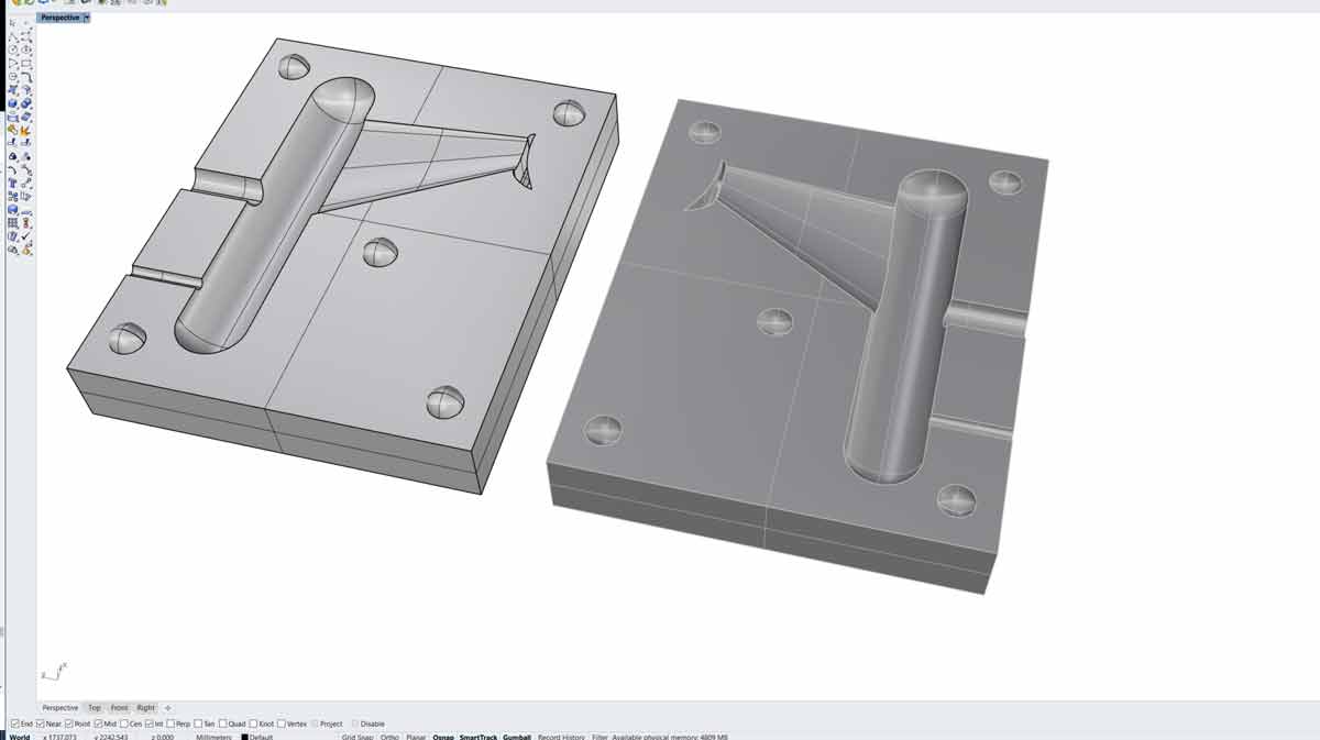
Made a two sided mould with cutouts to stear the two sides correcly in place
Made also one poaring hole 15mm wide and one 6mm air hole to let trapped air out when making the item

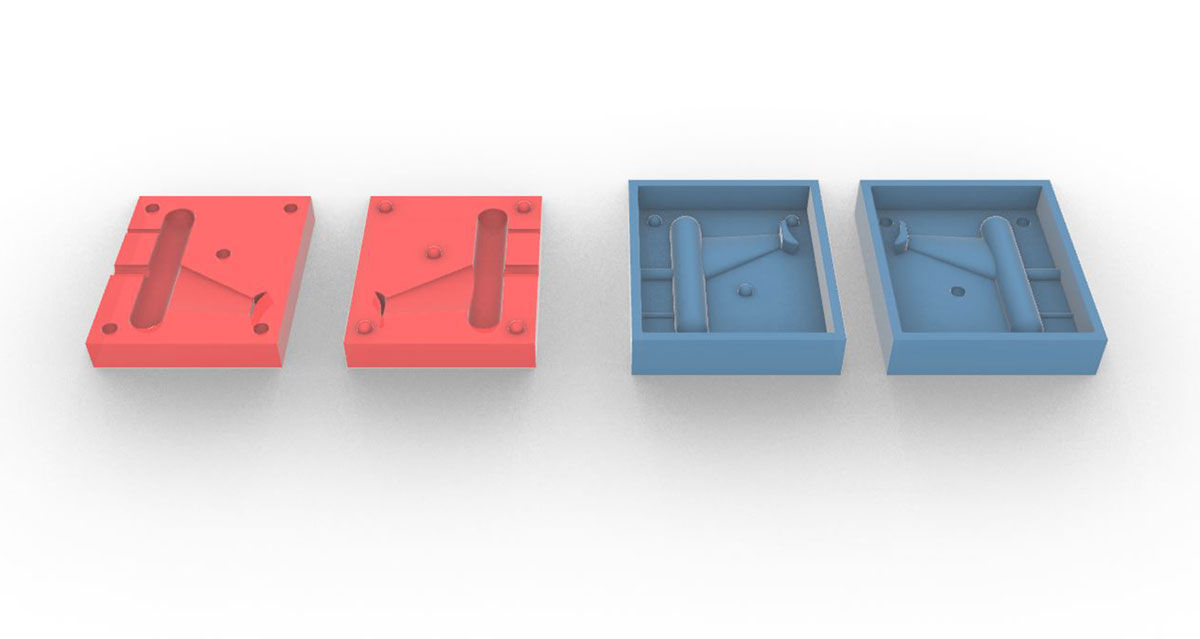
Here are both sides of the finished mould
Mould ready for Milling
Was not able to finish my mould this week because I did not have the nessasary materials to work with.
I will travel next week to Fablab Akureyri in North of Iceland to finish my Mould :-)
Here below is the file that I made in Rhino
turbine Bracket Mould.3dm /Final project video
Experiment
Experimenting on how Electric motors work.
Magnús St. Magnússon © 2020| v1
Madefor FabAcademy