4. Electronics production
This week is a great journey for me to compare 2020 Electronics production week to 2024. Here’s the group page. I will tell more about group assignment below.
Group assignment 2024
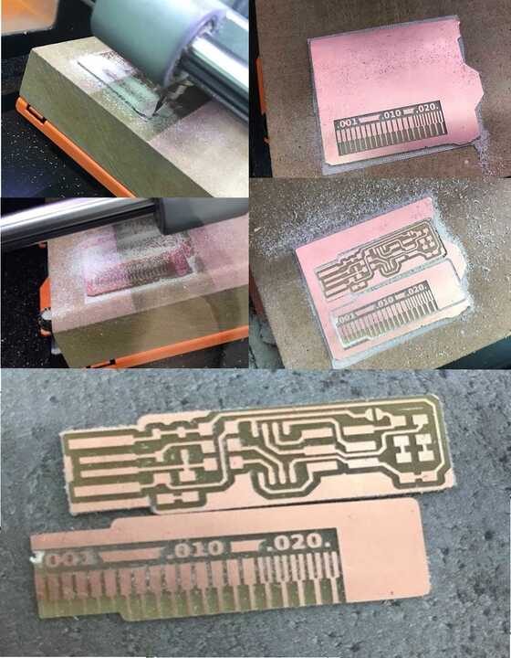
For a group assignment, we tested a V-cutter. We noted the diameters at each depth and adjusted settings for different thicknesses, starting with a simple test in Inkscape.
Using Fab Mods, we generated G-code from SVG files, setting a tool diameter of 0.4mm and a starting depth of 0.8mm to engrave lines from 0.1 to 0.5 mm thick. After previewing the cutting path, we loaded the G-code and began engraving, To save time, we manually write G-code to create a single line with increasing depth.
%
G17
G21
G40
G49
G54
G80
G90
G94
S11000
G00Z2.0000
M03
G00Z2.0000
G00X0.0000Y0.0000Z2.0000
G01 Z0 F100
G01 X40 Z-1.6
Z50
M05
M30
%
This code produced the following result:

We also drew the V-cutter shape with actual dimensions and solved it mathematically. Assuming a tip diameter of 0.2 mm, Areg developed a formula for calculating the parameters.
During testing, Areg and I created a SolidWorks drawing that automatically measured each depth. We used a tip diameter of 0.1 mm for calculations but could adjust to 0.2 mm if needed. Despite some uncertainties, we used theoretical approaches to calculate depth and thickness at a 30-degree angle using the model’s parameters.
2020 Making an in-circuit programmer FabTinyISP
First of all, I had to make PCB by milling material, as the material we used FR1. FR-1 is a hard, flat material that consists of a thin layer of copper over a non-conductive phenolic resin. It’s usually about the thickness of two or three credit cards
To mill FR1 I used the Roland SRM-20, which is small 3 axis milling machine.
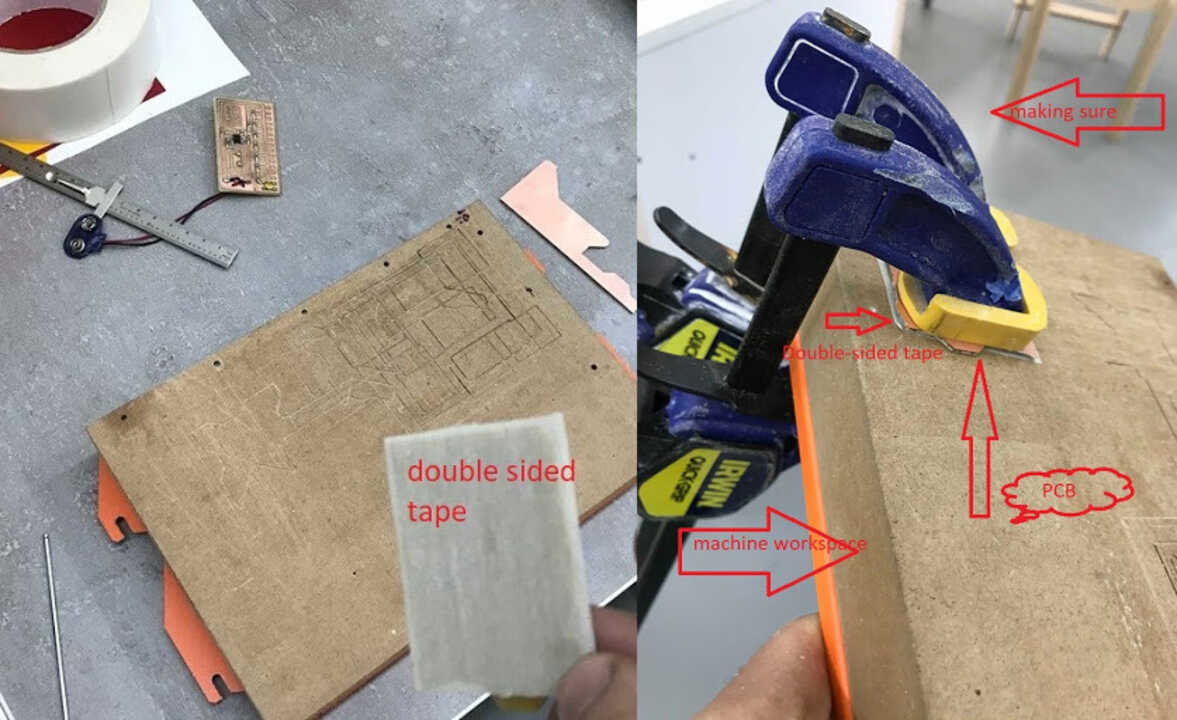
To start milling firstly I need to attach the PCB plate on the workspace of the machine, to do that I use the Double-sided tape.
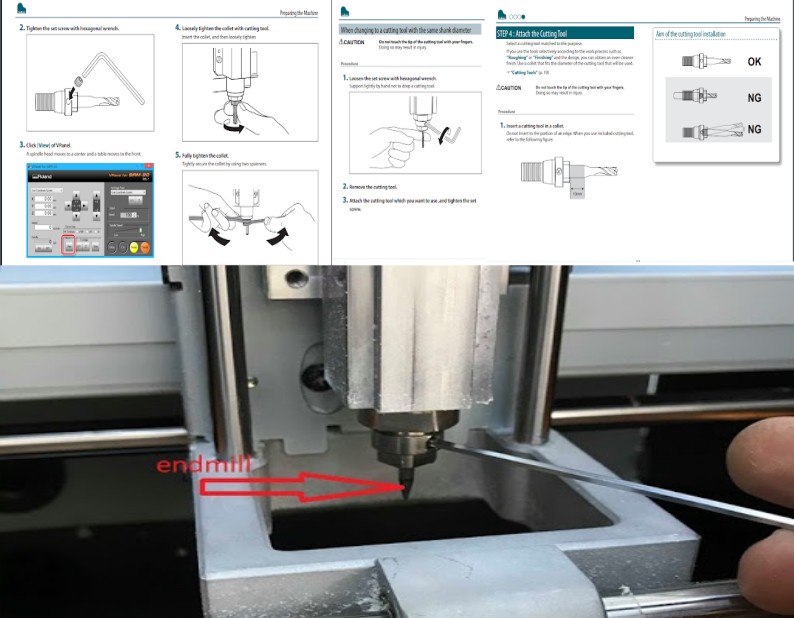
After putting the workspace back into the machine, I select the endmills I need - a 1/64 for milling traces and a 1/32 for profile cutting. First, I load the 1/64 end mill onto the spindle.
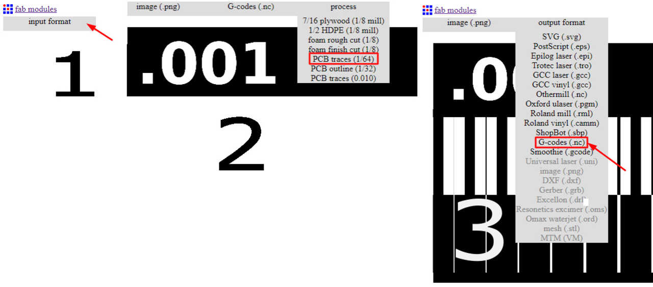
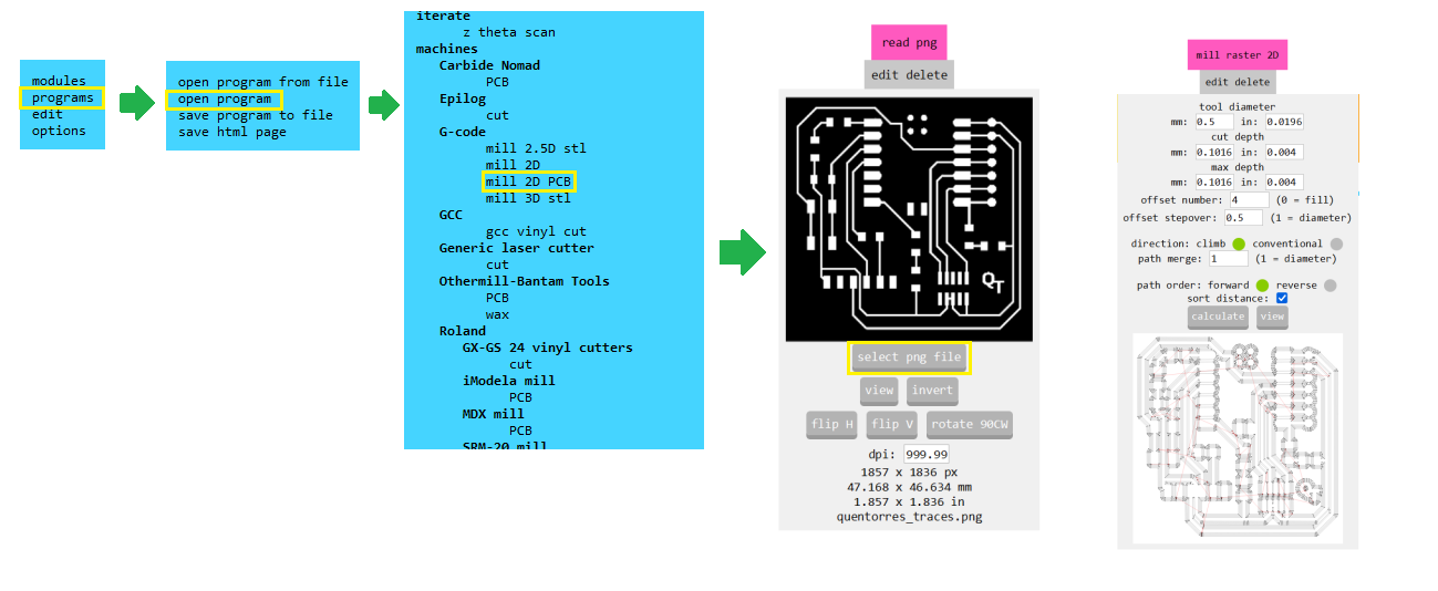
To make the CNC machine perform a task, I need the G-code. To generate the G-code, I use Fab Modules. Fab Modules provide a straightforward and enjoyable process. The first step involves inputting the format, which, in our case, is png. Next, I choose the output format, .nc, which corresponds to G-code. Then, I select the endmill, and that’s all; I can save it. Actually, it’s quite simple—all parameters have been chosen and set. Although I experimented with settings, I eventually reverted everything to its original configuration to minimize risks.
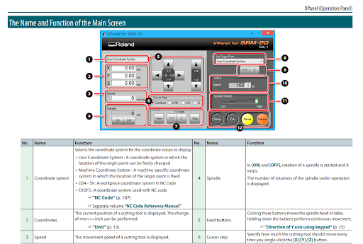
After obtaining the NC files, I open VPanel, which is Roland’s software. VPanel is user-friendly and simple software with just a few buttons.
After completing all the steps described above, I was ready to start machining. To do that, I pressed the ‘cut’ button, selected (input) .nc files, then pressed ‘output,’ and the magic began. However, not everything went as planned. What I mean is that I mixed up the G-codes, and as a result, my CAM test looks like a USB, but that wasn’t critical because the important part survived.
After completing the milling process, I removed the parts, cleaned the machine, and started reading tutorials about soldering. The second step was to solder components onto the PCB. At that time, I had no experience in soldering, which is why I tried soldering with non-working boards that were unneeded and got used to it in one hour. Our instructors helped me a lot to gain some skills in soldering. One of the rules they taught me was to keep the heating element clean by using a wet sponge. For soldering, first of all, I need a heating component to heat the point on the board, then press solder onto the heated point. It will melt and connect the component to the board. The soldering iron temperature is set to 350 degrees Celsius
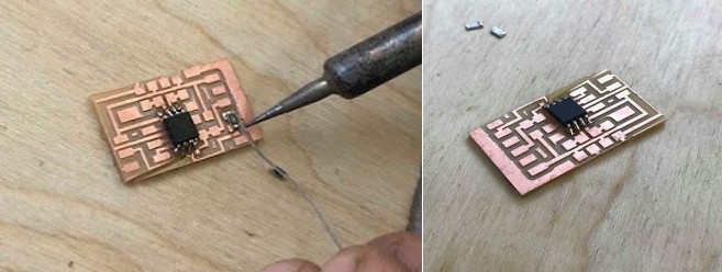
Having gained some experience, I started working on my PCB. The next suggestion from our instructor was to clean the board before starting soldering. Then we needed to gather the components
1x ATtiny45 or ATtiny85
2x 1kΩ resistors
2x 499Ω resistors
2x 49Ω resistors
2x 3.3v zener diodes
1x red LED
1x green LED
1x 100nF capacitor
1x 2x3 pin header
Programming
The final step was to program the board as a programmer. For that I used Brian’s documentation.
I used Azniv’s programmer. This was done in a few steps. First of all, Linux is needed for programming. Then, using the command line, I installed the software (CrossPack). To complete the installation, I followed the steps outlined in Brian Mayton’s tutorial, FabTinyISP_english, from FabAcademy. The tutorial is written very thoroughly and explains everything in detail. I can’t write too much about programming because I only followed the steps described in the tutorial, and unlike every other time when I do something with a tutorial, it worked perfectly.
I utilized an Ubuntu computer of Fab Lab that had both both “avrdude” and “avr-gcc” installed if you need to install them go HERE, and Azniv Hovhannisyan’s FabISP you can do it with AVR programmer AVRISP MKII that all Fab Labs have in house.
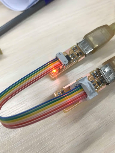
First we need to connect the programmer’s ISP pinheaders to our target board, then open the terminal at the code location. And execute the command “make flash.”
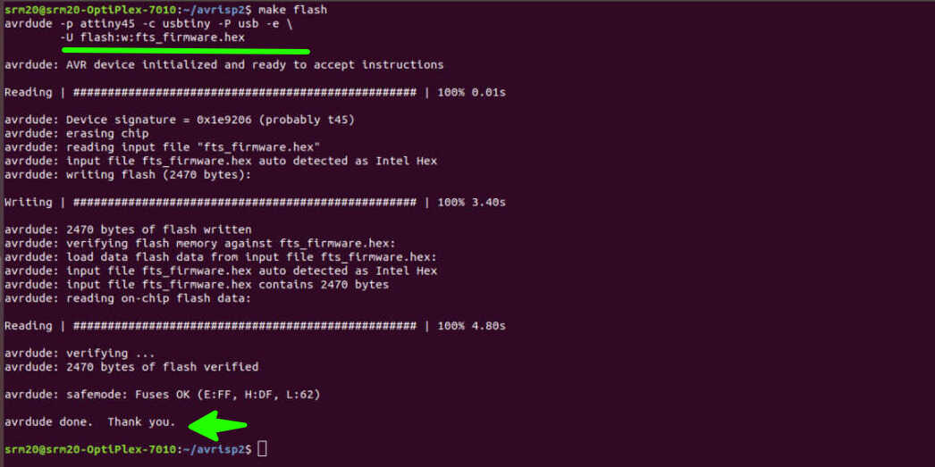
After this we run “make fuses” command I forgot to make the screenshot of this step.
Following this, I used the command “lsusb.” If a “Multiple Vendors USBtiny” device is detected, the process has succeeded. Strangely, I had to perform this procedure twice, possibly due to a connection issue.
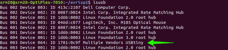
It’s important to make sure your USBtiny is recognised since in next two steps we disable the reset pin which means our ATtiny45 is not going to be programmed anymore the programming ability is desabled.
In order to do that we run “make rstdisbl” This disables the reset pin and “avrdude” will never ba ble to interface with this chip again.
After this we remove the
2024 Making of Quentorres. swd+uart adapter+hello board
This year we had to: Make and test a microcontroller development board extra credit: personalize the board extra credit: make it with another process
In 2020 I used FabModules but this time I got aquainted with Fab Mods which is much more powerful and capable program. I was surprised to learn that it has an integration with SVGpcb and even is able to drive Urumbu boards.
.Png to vector
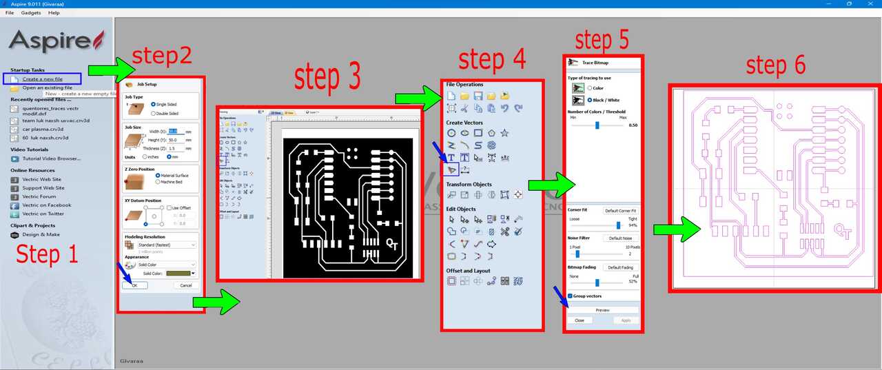
After experimenting with fab modules, I decided to pursue a different approach. Instead of using a .png file to generate G-code, I prefer working with vector files like .dxf or .svg for my modifications. The subsequent step involves transferring the PNG file to vectors. To achieve this, I utilized the CAD/CAM program known as Aspire 9.0, the same software used for our sizable CNC shopbot in the lab.
-
step 1. creating new file.
-
step 2. Setting up the sizes of our workpiece comes next. At this stage, we can input approximate dimensions, for example, 50x50, to define the size of the project.
-
step 3. Involves importing our PNG into Aspire, which is accomplished through a simple drag-and-drop process. Setting up the sizes of our workpiece comes next. At this stage, we can input approximate dimensions, for example, 50x50, to define the size of the project.
-
step 4. Using the tracing bitmap tool to extract vectors from our image is the next step in the process.
-
step 5. The original settings are suitable for our purpose, so we can proceed by simply previewing and applying them.
-
step 6. Remove the original PNG file from our workspace, and now our vector file is ready. We can proceed to export the vectors in any desired format. In my case, I find .dxf suitable as I plan to use AutoCAD for further modifications.
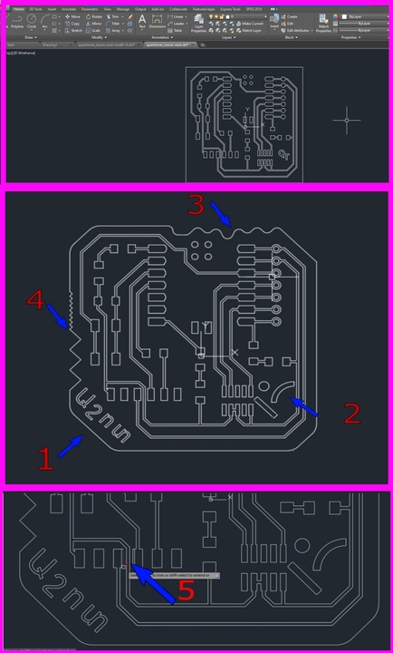
Modifying board in Autocad
Modifying the board in AutoCAD involves using various tools and commands to make changes to the vector file. You can manipulate and edit the design, adjust dimensions, add or remove elements, and perform other modifications as needed for your project. AutoCAD provides a comprehensive set of tools for precise and detailed design alterations.
-
modification 1. writing my name on borad in armenian
-
modification 2. inporting our lab’s logo and adding it to the empty spot of the boar.
-
modification 3 and 4. changing outter contour of the board by using line comand and fileting the sharp corners
-
modification 5. The most important modification. Since I am going to use a 0.5 mm end mill, which is a bit larger than the 1/64, there are traces that it can’t mill. To solve the problem, I trimmed two traces and made them 0.2 mm smaller
Last step is to export or save the autocad file in Dxf format. Now we are done with autocad and going bac to aspire for g code.
G-code with Aspire using one endmill for milling taces and cuting the board.
Import the Dxf file in Aspire
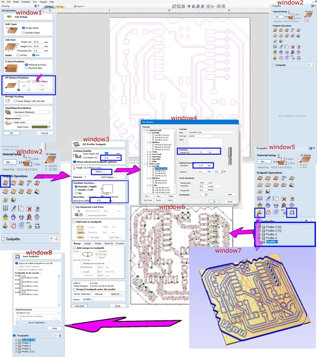 Uncheck the offset to set a new origin.
For traces in window 2, select the profile cutting tool and choose all vectors beside hole vectors.
In window 3, set the cut depth to 0.13 mm (because the thickness of copper coating on our board is 0.1-0.12 mm).
Also, in window 3, choose the end mill. Click on the select button; it will open window 4.
In window 4, choose the endmill (or create a new tool by changing the existing tool’s diameter).
Set the pass depth to 0.13 for traces. Press OK in window 4.
Choose the outside contour in window 3 and press calculate. Now we have calculated one toolpath, but it is not enough.
Copy toolpath profile1, choose it, and in window 3, set the offset to 0.25. Repeat the same 2 times so we will have 4 trace cutting profile toolpaths.
For the holes, choose the profile toolpath, set the cut depth to 1.6mm, and generate.
The last thing to do is to cut the outer profile, repeating the same thing by choosing the outer contour vector and changing inside to outside.
Then we can see the result on the main screen, window 6.
Check the result by pressing the preview toolpath button. It will show window 7. Press preview all toolpaths to see the simulation.
The last thing to do is to save the toolpath as a G-code. Press save and choose all toolpaths.
Uncheck the offset to set a new origin.
For traces in window 2, select the profile cutting tool and choose all vectors beside hole vectors.
In window 3, set the cut depth to 0.13 mm (because the thickness of copper coating on our board is 0.1-0.12 mm).
Also, in window 3, choose the end mill. Click on the select button; it will open window 4.
In window 4, choose the endmill (or create a new tool by changing the existing tool’s diameter).
Set the pass depth to 0.13 for traces. Press OK in window 4.
Choose the outside contour in window 3 and press calculate. Now we have calculated one toolpath, but it is not enough.
Copy toolpath profile1, choose it, and in window 3, set the offset to 0.25. Repeat the same 2 times so we will have 4 trace cutting profile toolpaths.
For the holes, choose the profile toolpath, set the cut depth to 1.6mm, and generate.
The last thing to do is to cut the outer profile, repeating the same thing by choosing the outer contour vector and changing inside to outside.
Then we can see the result on the main screen, window 6.
Check the result by pressing the preview toolpath button. It will show window 7. Press preview all toolpaths to see the simulation.
The last thing to do is to save the toolpath as a G-code. Press save and choose all toolpaths.
I have to be carefool with pass dephts and cutting speeds in gcode change spindel speed 11000, and feedrate 300mm/min.
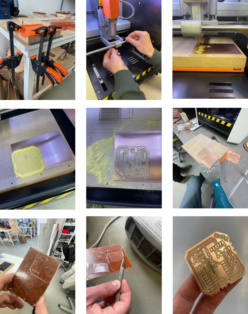
Cutting process
-
- Place FR-1 on the table and fix it with double-sided tape.
-
- Insert the endmill into the spindle.
-
- Set the origin point; in my case, it will be the left-down corner, as shown in the article above.
-
- Set the Z 0 point.
-
- Start the milling process.
-
- Remove the board from the table and clean the machine.
-
- remove tape by heating the board.
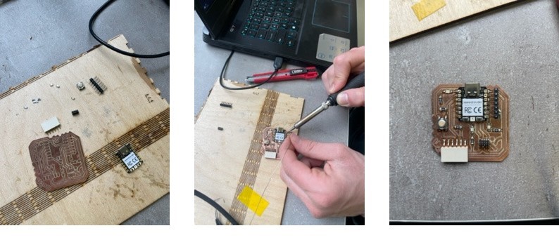
Soldering
Components we need. - SEEED STUDIO XIAO RP2040-1 - CONN HEADER SMD 10POS 1.27MM-1 - CONN HEADER SMD R/A 6POS 2.54MM-1 - Tactile Switch SPST-NO Top Actuated Surface Mount-1 - LED BLUE CLEAR 1206 SMD-3 - RES 1K OHM 1% 1/4W 1206-4 - RES 499 OHM 1% 1/4W 1206-1 - CONN HDR 7POS 0.1 TIN SMD*-2
Programming
As described in (Quentorres)[https://gitlab.fabcloud.org/pub/programmers/quentorres] documentation I downloaded (Arduino IDE)[https://www.arduino.cc/en/software] in my case it was version 2.3.1 then I started configuiring it to work with Xiao RP2040.
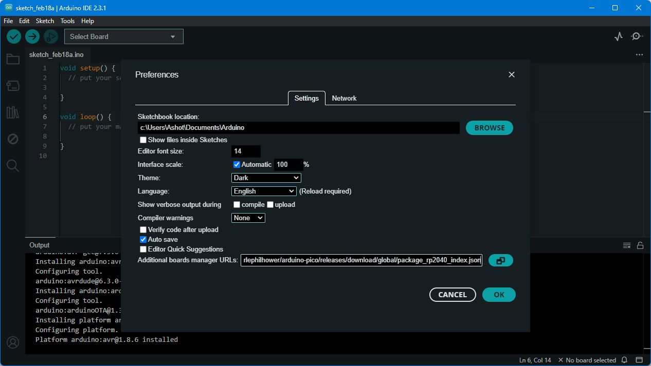
I added (Arduino-Pico by Earlephilhower)[https://github.com/earlephilhower/arduino-pico/releases/download/global/package_rp2040_index.json] in the Additional boards manager URLs under File > Preferances.
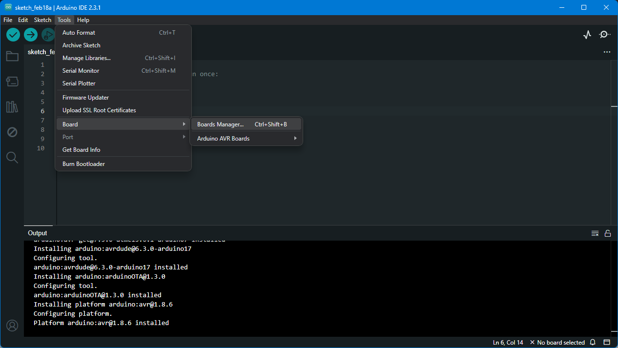
 Then navigated to Boards Manager
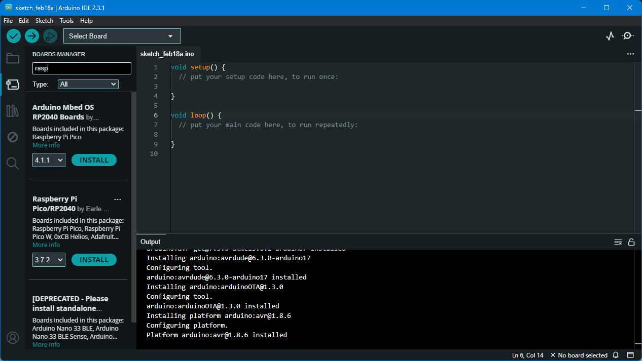
 And installed Raspberry PI Pico/RP2040 by using search bar.
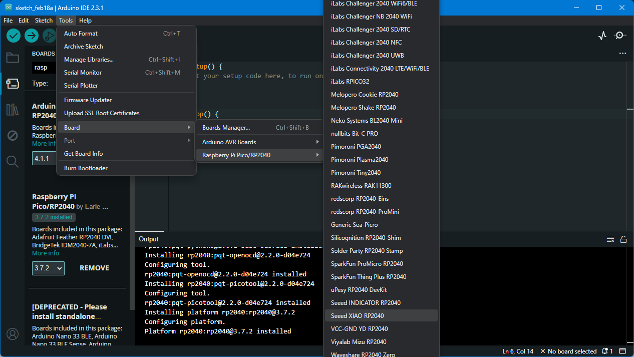
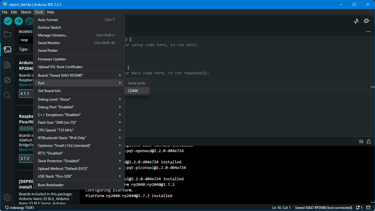
 Selected Seed XIAO RP2040 from Tools > Boards > Raspberry PI PICO/RP2040 > Seed XIAO RP2040.
 Then connected my board to PC and selected the port that appeared in my case COM8.
First I tried Blinking the LED that was connected to pin 26 as described in Quentorres tutorial using the Blink sketch from File > Examples > Basics > Blink. I just changed LedBuiltin to 26.
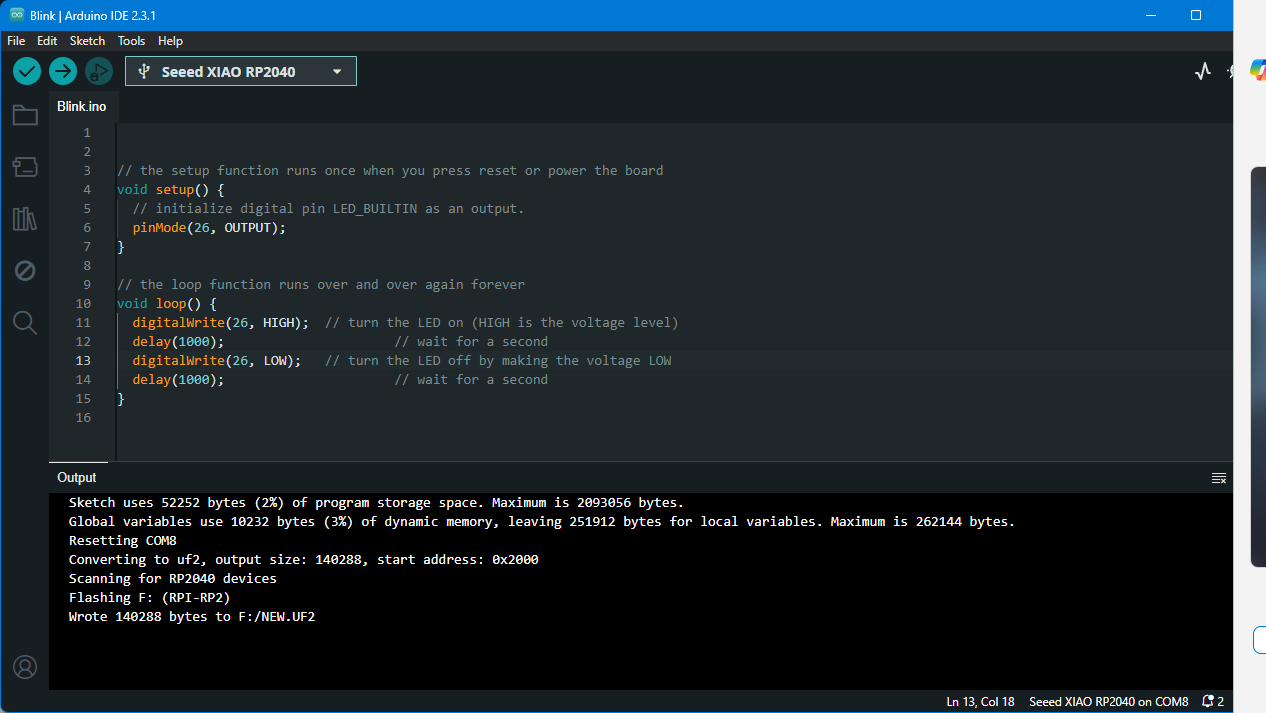 Here is the result!
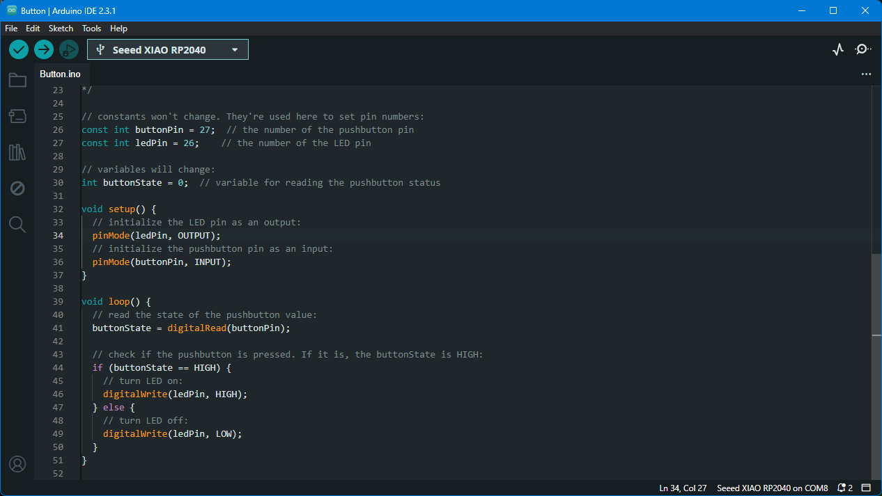
After this I decided to try something more and tried Blinking LEDs with the button. I used Button sketch from File > Examples > Digital > Button. First I tried blinkin the LED on pin 26
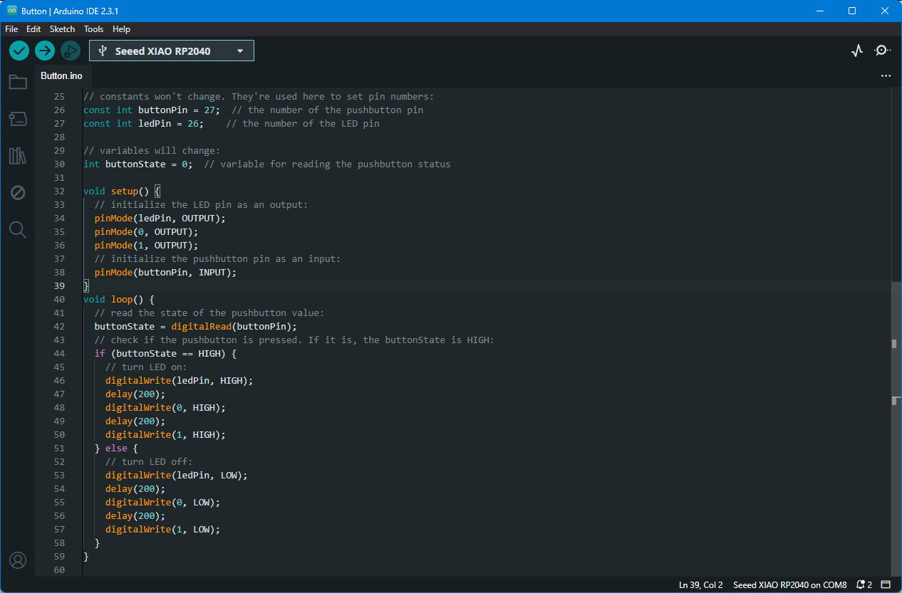
Then I’ve added two other buttons on pin 0 and pin 1 and made a sequence by adding delays after turning on each LED.
 Here is the result!
Here’s the selectable code in case someone needs to try it.
// constants won't change. They're used here to set pin numbers:
const int buttonPin = 27;  // the number of the pushbutton pin
const int ledPin = 26;    // the number of the LED pin

// variables will change:
int buttonState = 0;  // variable for reading the pushbutton status

void setup() {
  // initialize the LED pin as an output:
  pinMode(ledPin, OUTPUT);
  pinMode(0, OUTPUT);
  pinMode(1, OUTPUT);
  // initialize the pushbutton pin as an input:
  pinMode(buttonPin, INPUT);
}
void loop() {
  // read the state of the pushbutton value:
  buttonState = digitalRead(buttonPin);
  // check if the pushbutton is pressed. If it is, the buttonState is HIGH:
  if (buttonState == HIGH) {
    // turn LED on:
    digitalWrite(ledPin, HIGH);
    delay(200);
    digitalWrite(0, HIGH);
    delay(200);
    digitalWrite(1, HIGH);
  } else {
    // turn LED off:
    digitalWrite(ledPin, LOW);
    delay(200);
    digitalWrite(0, LOW);
    delay(200);
    digitalWrite(1, LOW);
  }
}
Conclusion
In 2020, I built an in-circuit programmer (FabTinyISP) using milling and soldering. I milled FR1 material with the Roland SRM-20, generated G-code with Fab Modules, and soldered components onto the PCB.
By 2024, the project evolved into Quentorres, a microcontroller development board. I used Fab Mods and AutoCAD to modify the design, adding my name in Armenian and refining traces for a 0.5 mm end mill. G-code was generated with Aspire, carefully setting pass depths and cutting speeds.
I soldered components like the SEEED STUDIO XIAO RP2040, connectors, a switch, LEDs, and resistors. Programming was done with the Arduino IDE for the Xiao RP2040 board, starting with simple LED blinking and moving to more complex sequences using buttons on pins 0, 1, and 26.