7. Computer-controlled machining
In 2020, I worked as a CNC machinist at our company, primarily operating a Chinese CNC milling machine, akin to a ShopBot, since 2018. During this period, I also had access to a metal milling machine and a turning machine, both equipped with CNC controllers.
My primary responsibility involved designing and crafting wooden patterns for our foundry. Throughout 2020, I utilized AutoCAD and Fusion 360 for these tasks. While at the workplace, I predominantly utilized the manufacturing features of Fusion 360, with occasional use of its design capabilities.
As of 2024, I am still employed at the same company, albeit in a different role. My current position occasionally involves designing various parts or mechanisms, and Fusion 360 remains one of my preferred tools for these tasks.
In 2020, my experience with Fab Academy played a pivotal role in helping me get started with Fusion 360, which has proven to be a valuable tool in my current role.
Group assignment
As part of our group assignment, we learned about machine safety, operation, and key components such as the spindle and Tool Holding Mechanism. We also familiarized ourselves with software like VCarve Pro and ShopBot 3. During practical sessions, we experimented with arranging pieces and cutting shapes, ensuring a snug fit within designated areas. Overall, the experience provided valuable insights into CNC machining processes and software utilization.
2020 experine
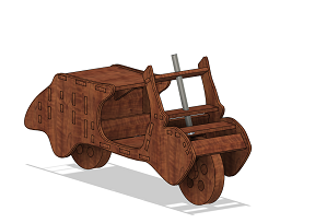
Machining Week marked the beginning of my final project journey. During this time, I made the decision to create a wooden, drivable scooter. In this pivotal week, my task involved designing and machining the frame for the scooter.
I initially attempted the design process in SolidWorks, but it proved time-consuming and somewhat challenging for me. Consequently, I decided to switch back to Fusion and commenced the design work in a more familiar and comfortable environment for me.
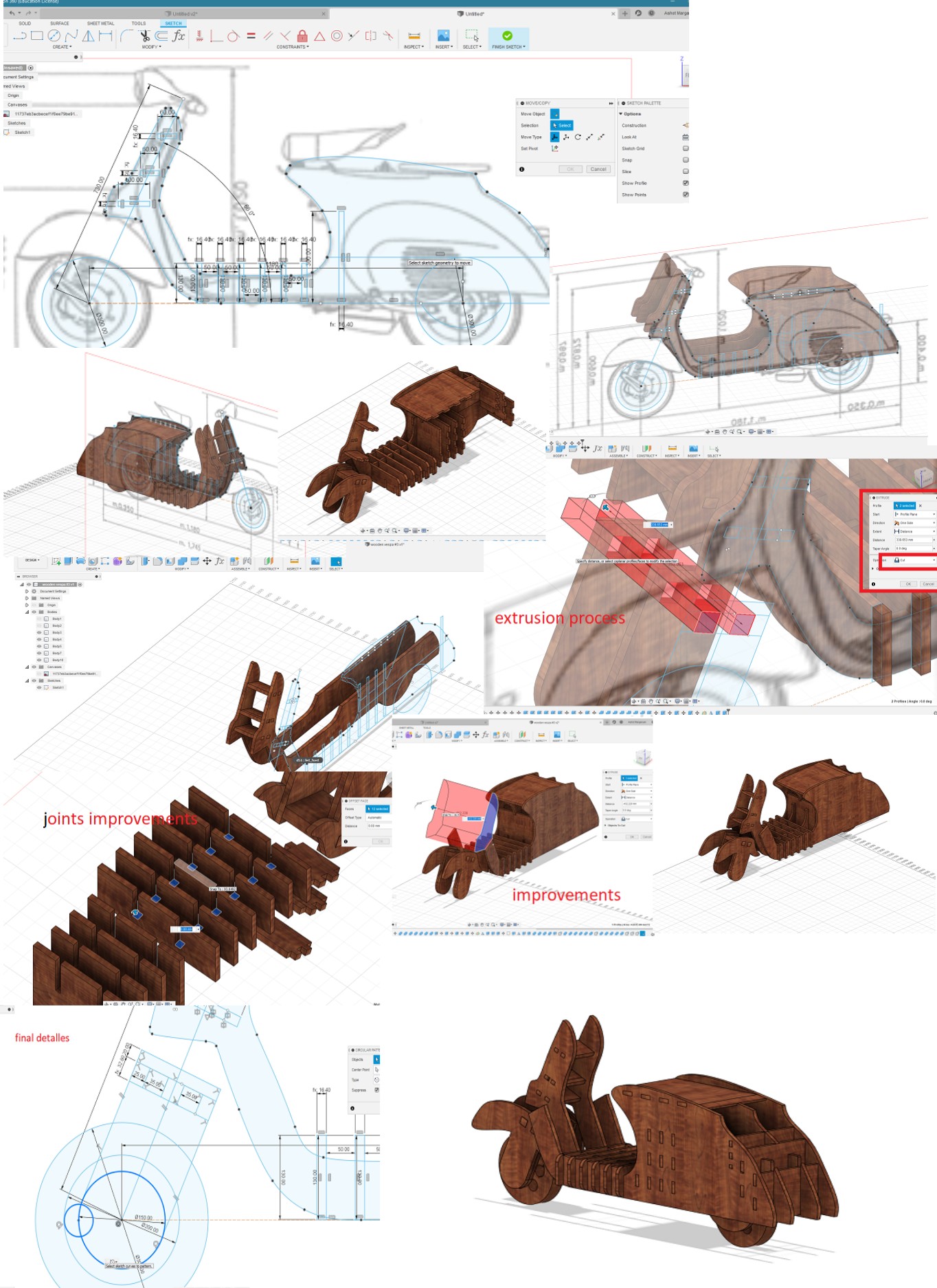
To design the wooden scooter, I required specific dimensions such as length, width, and height. I found a drawing on the internet and imported it into Fusion 360 for reference in my design process.
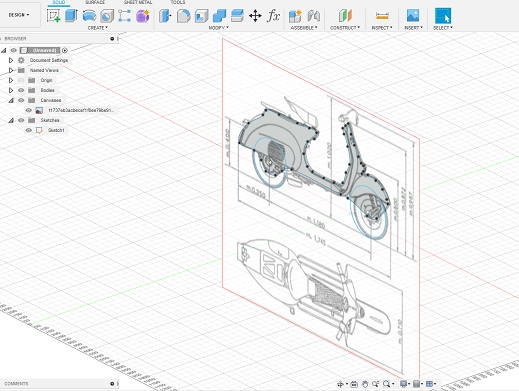
After importing the drawing with the actual scooter dimensions, I began sketching and outlining the main body panels. Subsequently, I extruded the side panel sketch and initiated a new sketch on it to design the joints. Following that, I mirrored the side panel and extruded the joints, choosing the cutting option in the extrude tool.
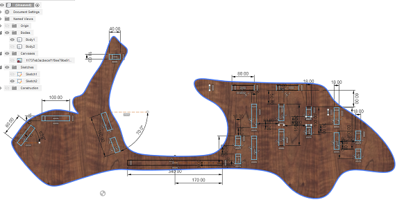
Using the same sketch, I designed the parts that would connect to the side panel and form the structure of the scooter.
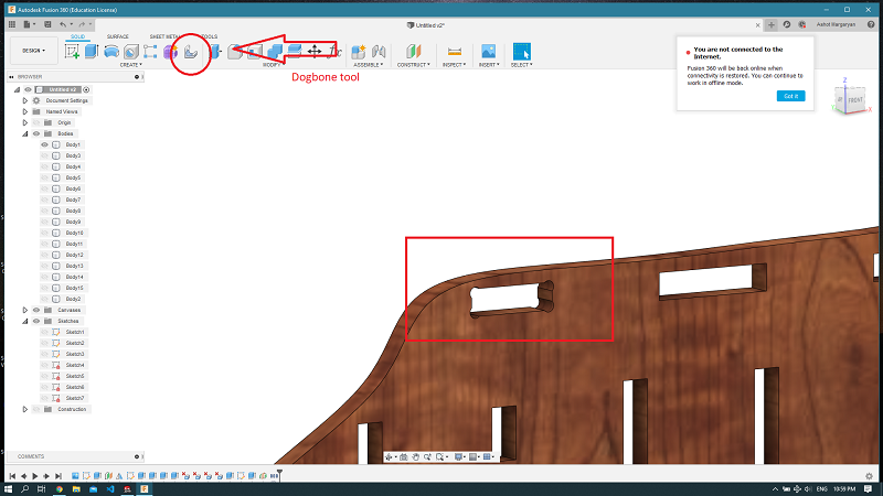
The Vespa was planned to be assembled using joints and assembled solely with the use of a hammer. Due to the scale of the project, numerous dog bone joints were required. To simplify my task, our instructor recommended a Fusion 360 add-in for creating dog bone joints in wooden joinery. My gratitude goes to them for creating such a useful tool. It operates by selecting the corners of the joints and configuring the end mill diameter and offsets.
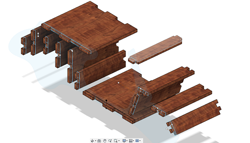
After a few hours of work, I completed the first version of the scooter design, which appeared a bit rough.
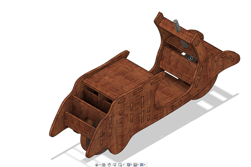
Consequently, I decided to remake the entire design. So, I started over by sketching and designing the other parts.
After completing the design, it’s time to move on to the machining phase, or more precisely, creating the toolpaths.
As our parts will be cut from 16mm plywood, and the standard size of a plywood sheet is 1520x1520 mm, we need to adapt to our ShopBot table size of 1200x2400 mm. Consequently, our setup will be 1200x1520, requiring us to cut the plywood sheet to fit the milling machine table. The dimensions of 1200x1520 are also crucial for creating our setup in the toolpath. The final step before transitioning from the design workspace to manufacturing is arranging our parts in one sketch. Fusion has a special arrangement tool for this purpose. It is evident that I will need more than one sheet of plywood, requiring me to manage and arrange the parts from the scooter multiple times for each new sheet.
CAM or Manufacturing in Fusion 360
There are numerous tutorials available for Fusion 360’s manufacturing environment. I would recommend Lars Christensen’s YouTube channel for learning both computer-aided design and computer-aided manufacturing in Fusion 360.
In the CAM environment, we have a toolbar at the top of our screen, and there are several steps to follow to create a functional toolpath. Let’s explore that toolbar. In Fusion, every window develops from left to right.
creating setup
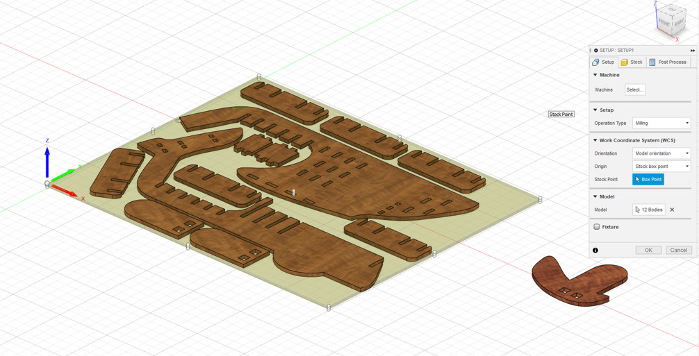
In Fusion 360, a “setup” refers to the configuration and definition of the machining environment for a particular job. It encompasses various parameters that specify how the CNC machine will interact with the workpiece during the manufacturing process. Key components of a setup include:
-
Work Coordinate System (WCS): This establishes the origin and orientation of the part within the CNC machine. It defines where the machining operations will take place in relation to the workpiece.
-
Stock Definition: This defines the raw material (stock) from which the final part will be machined. It includes dimensions such as the size and shape of the initial stock.
-
Model Orientation: Determines how the CAD model aligns with the CNC machine setup. This includes selecting the primary machining direction and ensuring the model is properly positioned in relation to the CNC machine.

creating toolpath
In Fusion 360, the distinction between 2D and 3D toolpaths lies in the dimensionality and complexity of the machining operation.
2D toolpaths are primarily used for machining simple 2D profiles or pockets, limited to movement in two dimensions (X and Y). They are suitable for flat parts or surfaces and commonly applied in contouring, pocketing, facing, or engraving operations. The workflow involves 2D sketches as input, defining the geometry to be machined, and generating toolpaths based on the sketch and tool information.
On the other hand, 3D toolpaths are designed for machining more complex 3D shapes and surfaces, involving movement in three dimensions (X, Y, and Z). They are ideal for parts with intricate contours or 3D sculpted surfaces, allowing for detailed machining operations. The workflow requires 3D models or surfaces as input, utilizing the 3D geometry to generate toolpaths that follow the contours and shapes of the model.
In summary, 2D toolpaths are simpler and suitable for flat or 2D parts, while 3D toolpaths are more advanced, catering to the machining of complex 3D shapes with intricate detailing on curved surfaces. Fusion 360 provides both options to accommodate a wide range of machining needs.
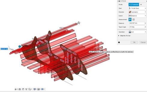
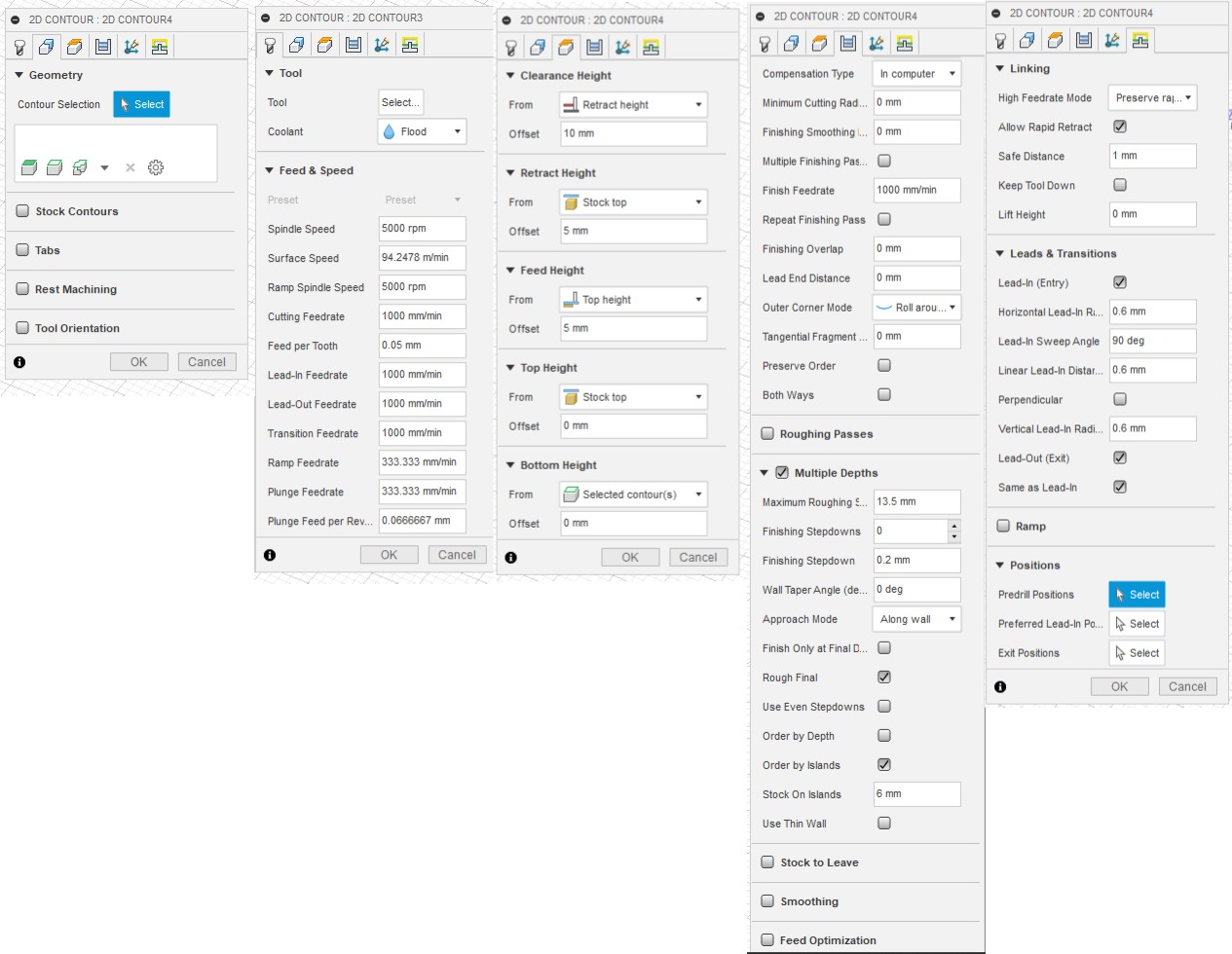
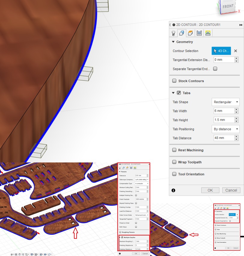
In our situation we need simple 2d contour toolpath. Creating a 2D contour toolpath in Fusion 360 involves a series of steps.
Selecting the Operation:
In the toolbar, go to the “2D” dropdown menu and choose “Contour.”
Setting Up the Geometry:
Define the toolpath by selecting the contours or edges of the geometry you want to machine. This is typically done by clicking on the desired edges in your 2D sketch or edge of the body.
Creating an endmill
Creating an endmill in Fusion 360 involves defining its physical characteristics and geometrical properties. Here’s a general overview of the process:
-
Accessing the Tool Library:
-
In Fusion 360, go to the “Manufacture” workspace.
-
Navigate to the “Tool Library” tab in the browser.
-
Creating a New Tool:
-
Click on the “+” button or right-click in the tool library to add a new tool.
-
Select the type of tool you want to create. In this case, choose “Mill Tool.”
-
Defining Tool Parameters:
- Enter essential parameters, such as the tool name, tool type (endmill), and units of measurement.
-
Specify the tool’s physical properties, including diameter, flute length, overall length, and other relevant dimensions.
-
Configuring Tool Geometry:
-
Define the endmill’s geometry, such as the number of flutes, helix angle, and end type (e.g., flat, ball, or corner radius).
-
Set additional parameters like corner radius, rake angle, and clearance angle if applicable.
-
Assigning Materials and Coatings:
-
Specify the material the endmill is made from and any coatings or treatments it may have.
-
Defining Feeds and Speeds:
-
Enter cutting parameters such as cutting speed, feed rate, and spindle speed based on the material being machined.
-
Adding to Tool Library:
-
After completing the tool definition, save it to the tool library for future use.
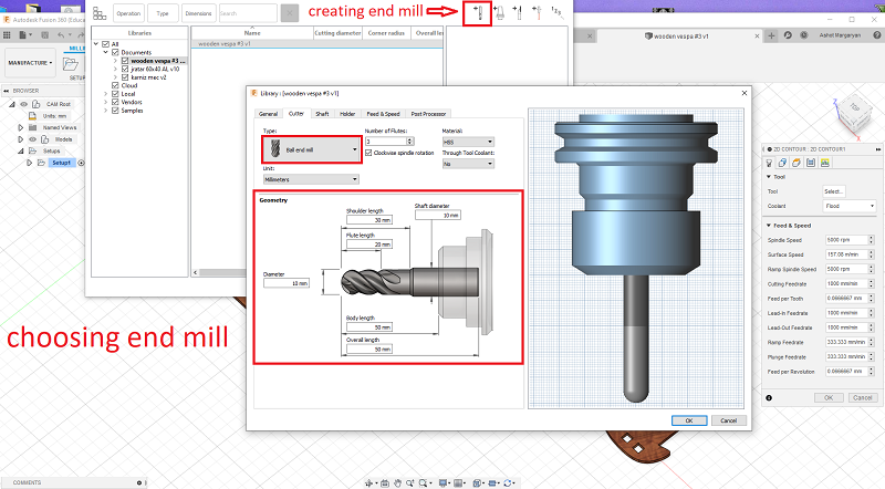
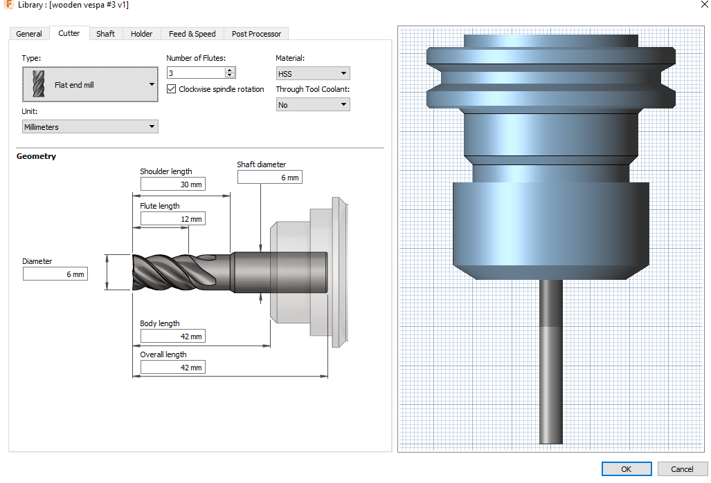
So, our tool is a 6mm HSS flat end mill with 2 flutes and without any coating, which is the most used in our lab.
Feeds and speed
Direction and Side of Cut:
Configure the tool’s movement direction along selected contours, choosing between clockwise or counterclockwise.
Cutting Strategies:
Specify cutting strategies (climb or conventional milling) to impact tool movement and chip formation during the machining process.
Helical Ramp (Optional):
Set up a helical ramp if needed, allowing the tool to descend gradually into the material to reduce stress on both the tool and the material.
Lead-In and Lead-Out:
Define lead-in and lead-out moves to ensure smooth transitions into and out of the material, preventing abrupt starts and stops that could cause tool marks.
Feed Rates and Speeds:
Set cutting feed rates, spindle speeds, and stepovers based on material properties and tool specifications, with the option to customize values.
As we are going to cut plywood on the ShopBot, we don’t need the exact speed to be set in the G-code because our speed can be regulated during machining process from the ShopBot desktop application (while holding the Shift key press “<” or “>” to increase or ecrease the feedrate, it increases or decreases 5mm/s per increment), in our case f=1000 mm/min or 16.6mm/s (wood and other soft materials are considered as “free machining”). On the other hand, that application doesn’t let us regulate spindle rotation speed (RPM), so it has to be preset during toolpath creation. In our case, it is 12,000 RPM.
Simulation:
Before generating the toolpath, use Fusion 360’s simulation tools to preview the operation, verifying the accuracy of the toolpath and identifying any potential issues.
Toolpath Generation:
Once satisfied with the configured parameters and simulation, click on the “OK” or “Generate” button to create the 2D contour toolpath.
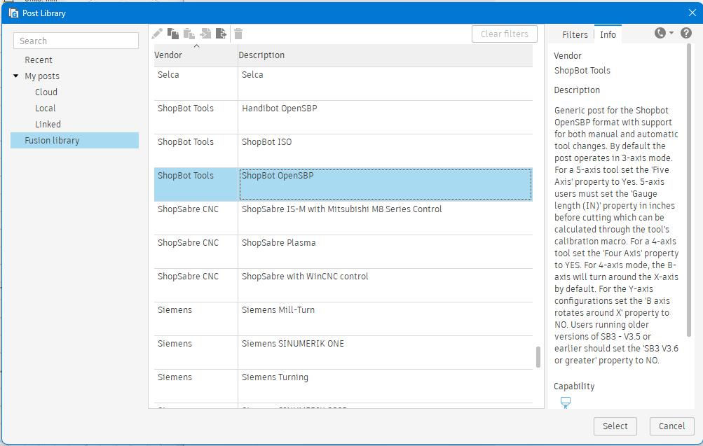
Post-Processing:
After generating the toolpath, post-process it to obtain the G-code required for your specific CNC machine. Fusion 360 provides options to select the appropriate post-processor based on your machine. In our case it can will be shopbot sbt. Copy it to the local library.
Machining(cutting)
Personal Protective Equipment (PPE):
Why it’s important: PPE is designed to protect individuals from potential hazards. Safety glasses or goggles safeguard the eyes from debris, hearing protection guards against loud noise, and closed-toe shoes offer foot protection. Avoiding loose clothing and jewelry reduces the risk of entanglement with moving parts. Takeaway: Always prioritize the use of appropriate PPE to minimize the risk of injuries.
Emergency Stop:
Why it’s important: The emergency stop button is a critical safety feature that allows users to quickly halt machine operations in case of emergencies or unexpected issues. Takeaway: Ensure that everyone using the CNC machine knows the location of the emergency stop button and understands how to use it effectively.
Workspace Organization:
Why it’s important: A clean and organized workspace reduces the risk of accidents, such as tripping or falling. Removing unnecessary tools, materials, and obstacles helps maintain a clear and safe environment. Takeaway: Regularly inspect and organize the workspace to eliminate potential hazards and maintain a safe working area.
Material Securing:
Why it’s important: Properly securing materials with clamps or fixtures prevents movement or displacement during the milling process. This is crucial for maintaining accuracy and preventing accidents. Takeaway: Prioritize the secure fastening of materials before starting the CNC machine to ensure stability and prevent any mishaps.
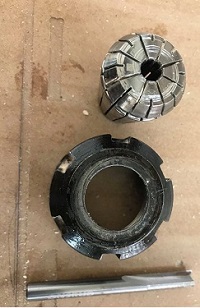
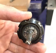
Install the End Mill:
Ensure the appropriate end mill is securely tightened in the machine’s spindle.
Position the Spindle Above the Material:
Using manual jogging or the machine’s controls, position the spindle accurately above the starting point on the material.
Lower the Spindle to Touch the Material or use the Z axis ziroing plate. Don’t forget about setting up X and Y axis zero point (origin).
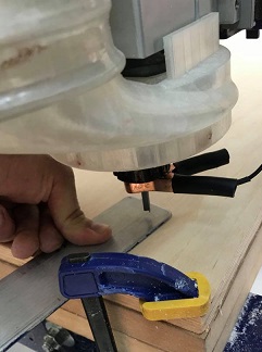
At this point, we are ready to start the machine. Since it was covid lockdown I did my machining jobs intermitently and with long intervals months. I used quick release G-clamps to secure my material to the spoilboard.
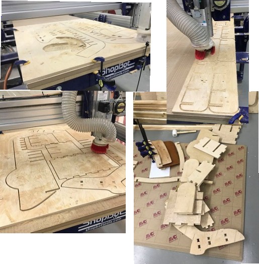
I used sanding machine (with 120 grain sandpaper) to sand the surfaces of the parts this also removes small chips left on the edges.
Assembling
Assembling the process requires three different hammers and hours of hammering. I think photos will better represent the assembling process. As the quantity of tabs was too much, it would have taken me forever to sand them down. So, I used a grinding machine and a sandpaper disc to remove them.
I made my tolerance test with just one joint and a sheet of plywood. Then I used different sheets and many joints in one row, which made the registration much tighter. This is why I needed so much hammering and sanding. After this experience, I learned that multiple joints in one row do not act the same. Even if all your joints are perfect, there’s still the factor of the curvature of the material, which can make registration very hard. Unfortunately, I didn’t take many photos of the sanding process, but I have to say that when you have so many (approximately 100) joints, there’s little chance to avoid sanding.
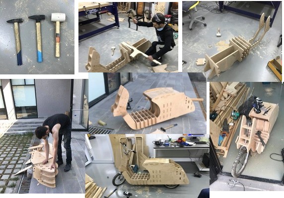
The hammering process needs to be done without excessive enthusiasm. It’s better to use a sacrificial piece of wood (you can see it in the photos above) between the hammering spots and the hammer, as this could prevent delamination of the plywood or damage to the corners.
Conclusion
In conclusion, my CNC machining journey, marked by Fusion 360 proficiency and ShopBot utilization, was exemplified in the creation of a drivable wooden scooter. From design intricacies to material machining and safety considerations, this project encapsulated the synergy between technology, craftsmanship, and safety protocols. The experience not only demonstrated the versatility of F usion 360 but also emphasized the importance of precision, adaptability, and meticulous assembly in realizing a complex project. The integration of innovative design tools and hands-on machining skills continues to define my professional trajectory in CNC technology.