6. Embedded programming
From 2020 documentation.
About Arduino
Arduino, an open-source electronics platform, is like a creative toolkit for learning and making cool stuff. Created in the early 2000s, Arduino boards are user-friendly mini-computers that make coding and electronics fun. Students use them to understand how things work, from blinking lights to more complex projects. In the DIY world, Arduino is a superstar, helping hobbyists bring their ideas to life, like crafting gadgets or robots. It’s not just for fun – companies use it too for quick prototypes. Despite a few challenges, Arduino’s friendly community and constant improvements make it a go-to for learning and creating in the electronic world.
Paying with Arduino during lockdown
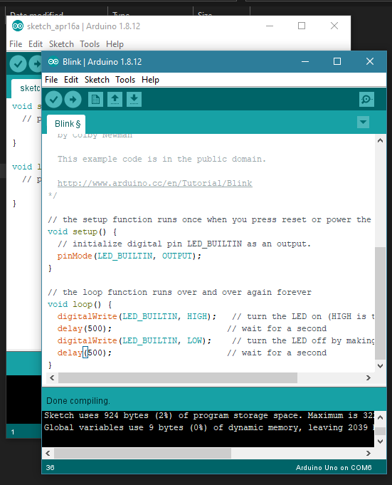
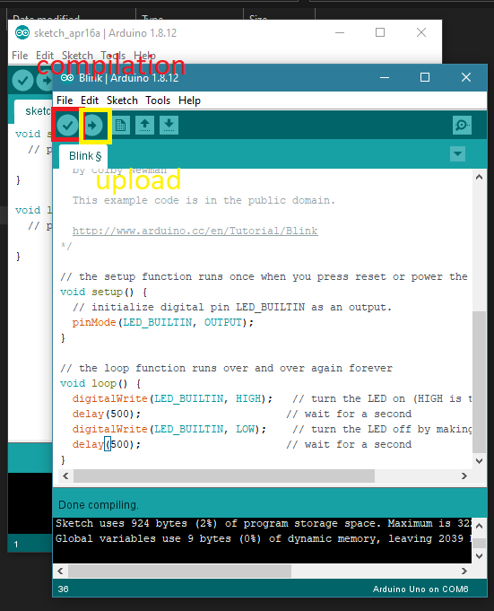
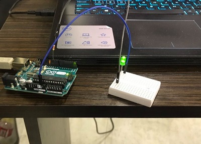
The kit is equipped with Arduino boards, breadboards, wiring, LEDs, stepper motors, and various sensors. To initiate the process, I first downloaded the Arduino software and connected the board to the computer for programming. The software comes preloaded with basic programs for tasks like toggling LEDs. My initial accomplishment was modifying the blinking frequency of the built-in LED. Following this, I attempted to replicate the LED blinking on a breadboard. I connected the breadboard to the Arduino using the 11th digital port, inserted a 220-ohm resistor, and grounded the circuit with a second wire. Executing the program resulted in successful LED operation.
Subsequently, I expanded my project by incorporating a button on the breadboard to control the LED’s on-off functionality. Admittedly, programming the Arduino for this task was not challenging, thanks to the abundance of tutorials and readily available open-source codes. For this specific implementation, I referred to a tultoria that guided me through the process of integrating the button functionality.
Back to lab 2020
After quarantine and due to other reasons, I am finally back in the lab. I have started working on the weeks that I missed, and one of them involves embedded programming. Due to the limited time and ongoing COVID-related issues, we were allowed to work on one of Neil’s boards. I chose the ‘Hello RGB LED’ board. My first step was to download the traces and the interior design of the RGB hello board. Afterward, I generated G codes using fabmodules.org.
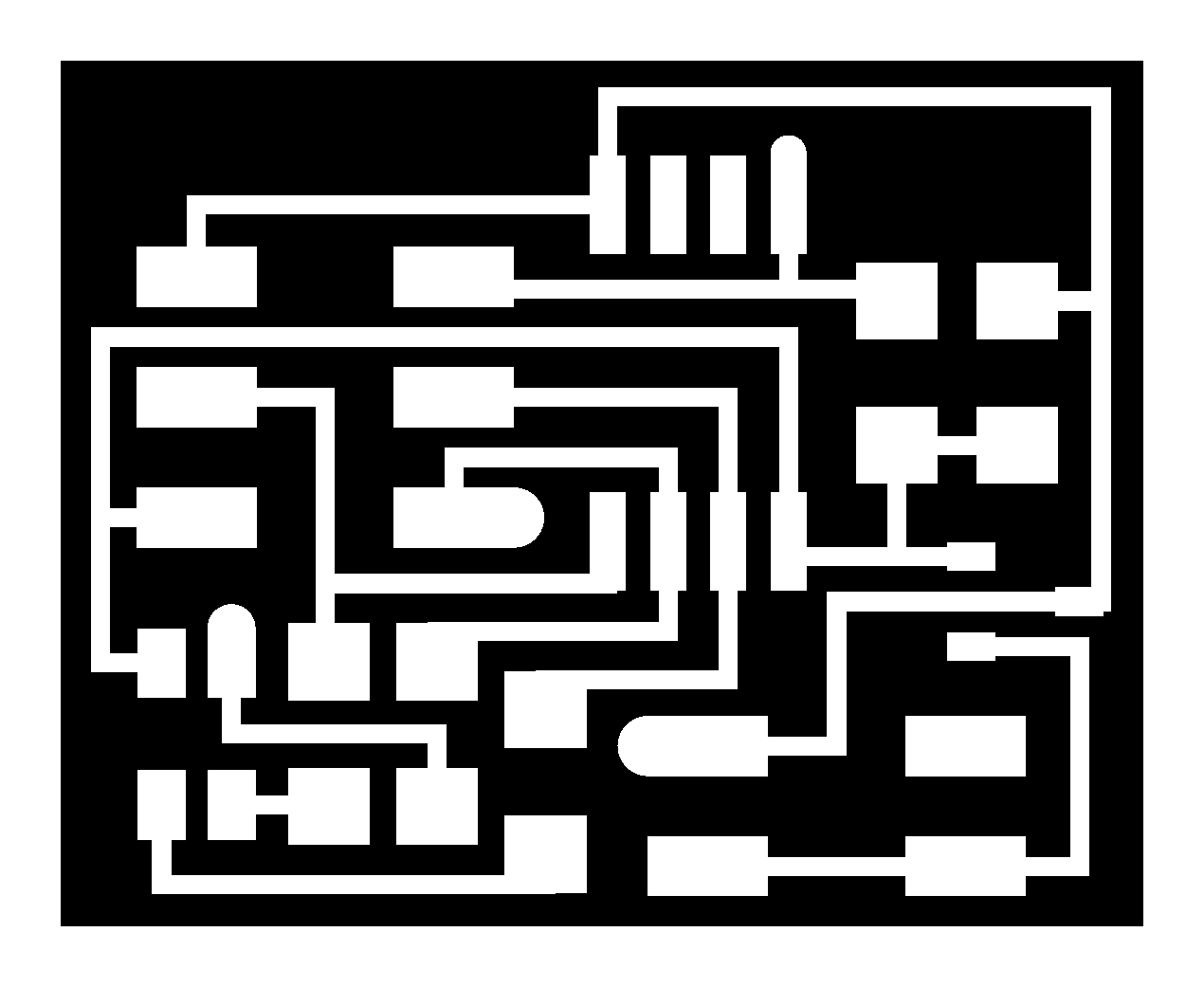
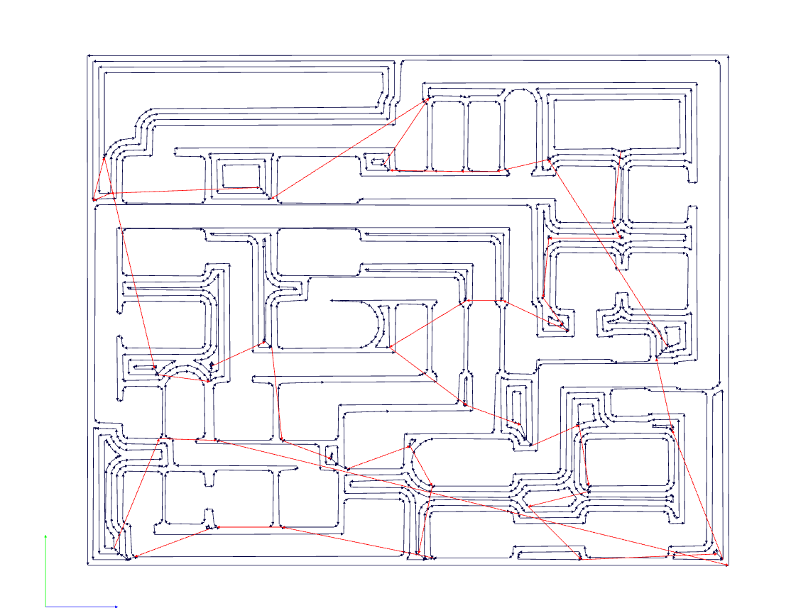
After obtaining the G-code, I milled the traces with a 1/64-inch end mill, and then cut it with a 1/32-inch end mill. The second step was the most challenging for me, as it involved finding the components
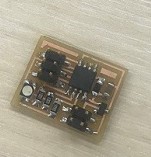
components
After components were found I solder the board.
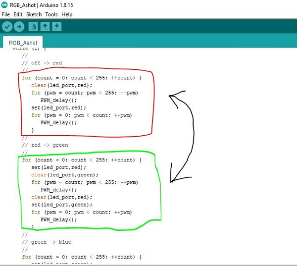
Code Example
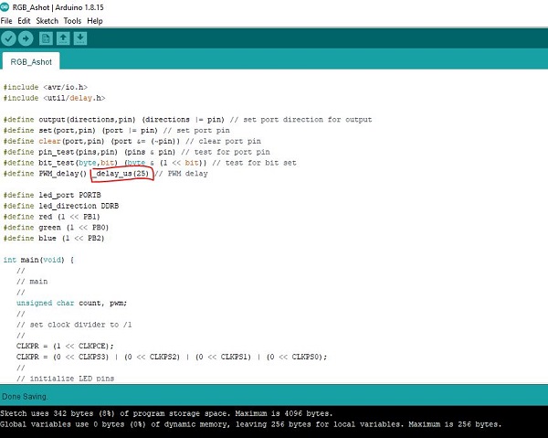
And let’s start the party. I begin programming and playing with the board. Here, I have changed the delay time and color sequence.
//
// hello.RGB.45.c
//
// RGB LED software PWM hello-world
//
// Neil Gershenfeld
// 11/10/10
//
// (c) Massachusetts Institute of Technology 2010
// This work may be reproduced, modified, distributed,
// performed, and displayed for any purpose. Copyright is
// retained and must be preserved. The work is provided
// as is; no warranty is provided, and users accept all
// liability.
//

#include
#include

#define output(directions,pin) (directions |= pin) // set port direction for output
#define set(port,pin) (port |= pin) // set port pin
#define clear(port,pin) (port &= (~pin)) // clear port pin
#define pin_test(pins,pin) (pins & pin) // test for port pin
#define bit_test(byte,bit) (byte & (1 << bit)) // test for bit set
#define PWM_delay() _delay_us(10) // PWM delay

#define led_port PORTB
#define led_direction DDRB
#define red (1 << PB1)
#define green (1 << PB0)
#define blue (1 << PB2)

int main(void) {
   //
   // main
   //
   unsigned char count, pwm;
   //
   // set clock divider to /1
   //
   CLKPR = (1 << CLKPCE);
   CLKPR = (0 << CLKPS3) | (0 << CLKPS2) | (0 << CLKPS1) | (0 << CLKPS0);
   //
   // initialize LED pins
   //
   set(led_port, red);
   output(led_direction, red);
   set(led_port, green);
   output(led_direction, green);
   set(led_port, blue);
   output(led_direction, blue);
   //
   // main loop
   //
   while (1) {
      //
      // off -> red
      //

      for (count = 0; count < 255; ++count) {
         set(led_port,red);
         clear(led_port,green);
         for (pwm = count; pwm < 255; ++pwm)
            PWM_delay();
         clear(led_port,red);
         set(led_port,green);
         for (pwm = 0; pwm < count; ++pwm)
            PWM_delay();
         }

      for (count = 0; count < 255; ++count) {
         clear(led_port,red);
         for (pwm = count; pwm < 255; ++pwm)
            PWM_delay();
         set(led_port,red);
         for (pwm = 0; pwm < count; ++pwm)
            PWM_delay();
         }
      //
      // red -> green
      //

      //
      // green -> blue
      //
      for (count = 0; count < 255; ++count) {
         set(led_port,green);
         clear(led_port,blue);
         for (pwm = count; pwm < 255; ++pwm)
            PWM_delay();
         clear(led_port,green);
         set(led_port,blue);
         for (pwm = 0; pwm < count; ++pwm)
            PWM_delay();
         }
      //
      // blue -> on
      //
      for (count = 0; count < 255; ++count) {
         set(led_port,blue);
         clear(led_port,green);
         clear(led_port,red);
         for (pwm = count; pwm < 255; ++pwm)
            PWM_delay();
         set(led_port,blue);
         set(led_port,green);
         set(led_port,red);
         for (pwm = 0; pwm < count; ++pwm)
            PWM_delay();
         }

      //
      // on -> off
      //
      for (count = 0; count < 255; ++count) {
         set(led_port,blue);
         set(led_port,green);
         set(led_port,red);
         for (pwm = count; pwm < 255; ++pwm)
            PWM_delay();
         clear(led_port,blue);
         clear(led_port,green);
         clear(led_port,red);
         for (pwm = 0; pwm < count; ++pwm)
            PWM_delay();
         }
      }
   }
2024 Electronics production week rerelated
Group assignment
Here is our group assignment page for Embedded Programming.
Comparison of RP2040 and ATtiny1614
Microcontroller Architecture: RP2040: Based on the ARM Cortex-M0+ architecture, offering a 32-bit processing core. ATtiny1614: Part of the AVR family, featuring an 8-bit AVR core.
Processing Power: RP2040: Offers higher processing power with its 32-bit architecture, suitable for complex applications. ATtiny1614: Provides sufficient processing power for simpler tasks typical of 8-bit microcontrollers.
Memory: RP2040: Typically equipped with larger memory capacities, including both flash and RAM, suitable for storing code and data for more extensive applications. ATtiny1614: Offers smaller memory capacities compared to the RP2040, appropriate for smaller-scale applications.
Peripherals and Features: RP2040: Offers a wide range of peripherals and features, including GPIO pins, UART, SPI, I2C, PWM, ADC, and more, suitable for diverse applications. ATtiny1614: Provides a basic set of peripherals such as GPIO pins, UART, SPI, I2C, and timers, suitable for simpler applications.
Development Environment: RP2040: Supports various development environments, including the official Raspberry Pi Pico SDK, MicroPython, CircuitPython, Arduino, and more, offering flexibility and ease of use. ATtiny1614: Typically programmed using the Atmel Studio IDE or Arduino IDE, providing a straightforward development environment for AVR-based microcontrollers.
Power Consumption: RP2040: Consumes moderate power, depending on the application and usage. ATtiny1614: Offers low power consumption, making it suitable for battery-operated or power-sensitive applications.
Cost: RP2040: Generally available at a competitive price point, considering its features and performance. ATtiny1614: Offers a cost-effective solution for simpler applications, with lower overall system cost.
Application Areas: RP2040: Suitable for a wide range of applications, including IoT devices, embedded systems, robotics, automation, and more. ATtiny1614: Ideal for simpler applications such as sensors, actuators, small-scale automation, and low-power devices.
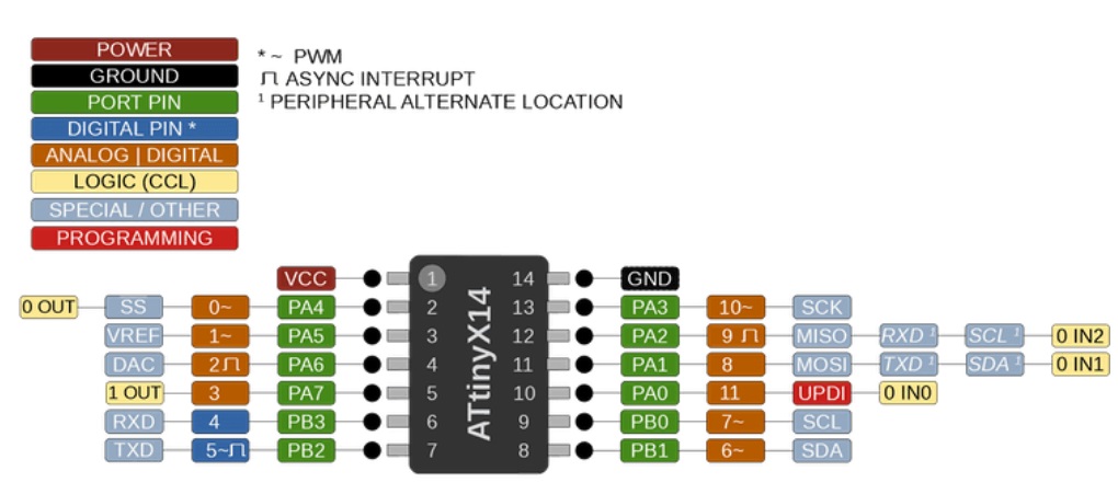
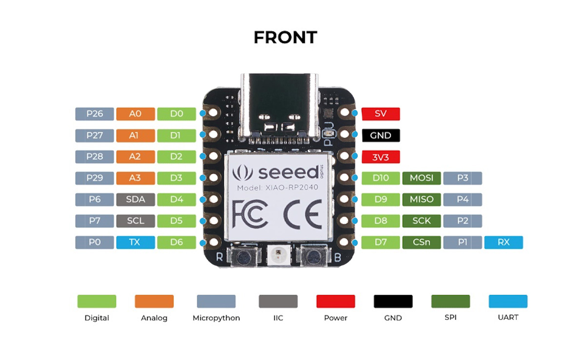
compared their pins configurations
ATtiny1614:
RP2040:
In summary, the RP2040 and ATtiny1614 microcontrollers offer different features, performance levels, and application areas. The choice between them depends on the specific requirements of the project, including processing power, memory, peripherals, power consumption, and cost considerations.
High level language vs low level language for programming
During this experiment, we evaluated various programming approaches on the RP2040 microcontroller. The objective was to compare the execution speed between a program developed using the Arduino environment (utilizing functions like pinMode() and digitalWrite()) and a program written “bare metal,” which directly accesses the hardware registers.
Results
We found that “bare metal” get’s us 13.3 times higher rates of operation than when using arduino workflow that has libraries, bootloaders etc…
| microcontroller | language | pwm |
|---|---|---|
| RP2040 | arduino | 590.590 kHz |
| RP2040 | “bare metal” | 7812580 kHz |
2024 experience
I did this part during electronics producion week but I’m also documenting it here.
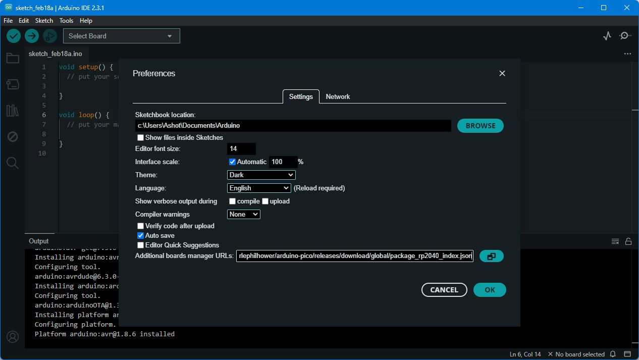
As described in Quentorres documentation I downloaded Arduino IDE in my case it was version 2.3.1 then I started configuiring it to work with Xiao RP2040.
I added Arduino-Pico by Earlephilhower in the Additional boards manager URLs under File > Preferances.
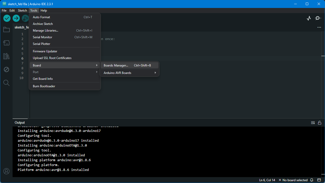
 Then navigated to Boards Manager
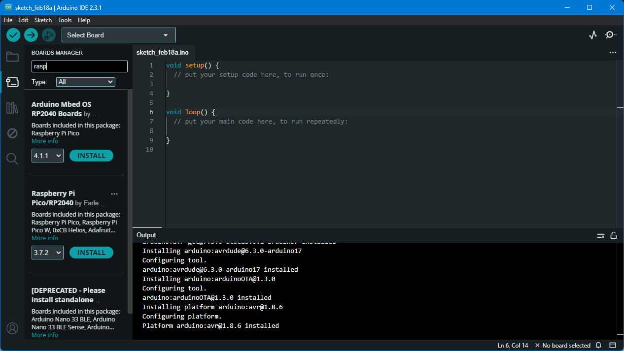
 And installed Raspberry PI Pico/RP2040 by using search bar.
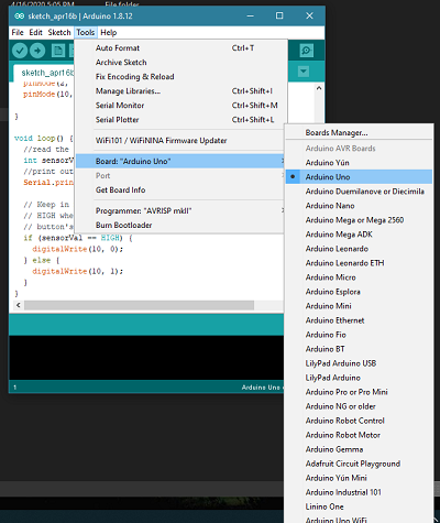
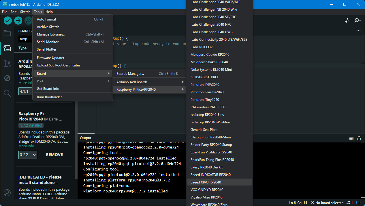
 Selected Seed XIAO RP2040 from Tools > Boards > Raspberry PI PICO/RP2040 > Seed XIAO RP2040.
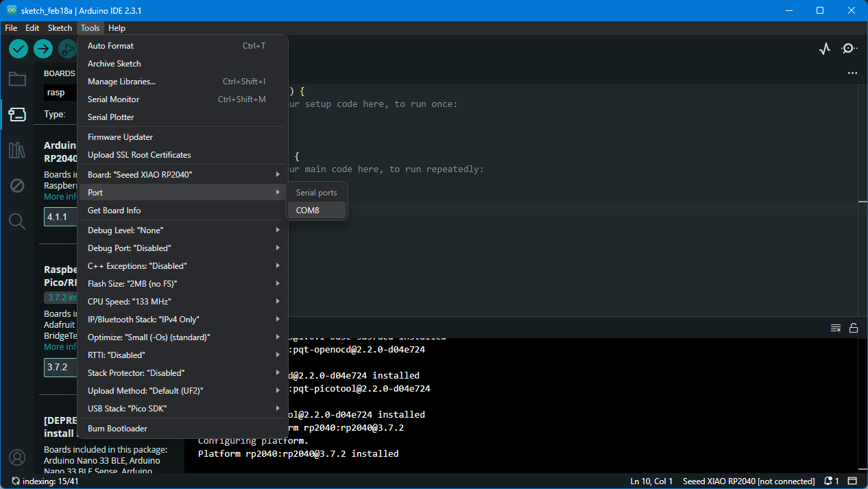
 Then connected my board to PC and selected the port that appeared in my case COM8.
First I tried Blinking the LED that was connected to pin 26 as described in Quentorres tutorial using the Blink sketch from File > Examples > Basics > Blink. I just changed LedBuiltin to 26.
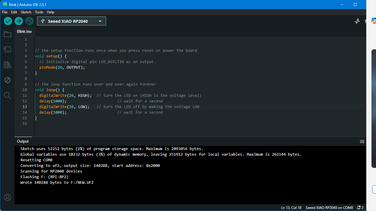 Here is the result!
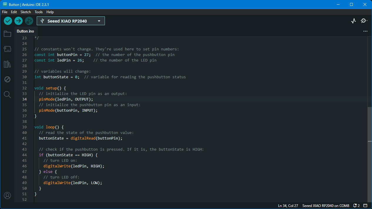
After this I decided to try something more and tried Blinking LEDs with the button. I used Button sketch from File > Examples > Digital > Button. First I tried blinkin the LED on pin 26
Then I’ve added two other buttons on pin 0 and pin 1 and made a sequence by adding delays after turning on each LED.
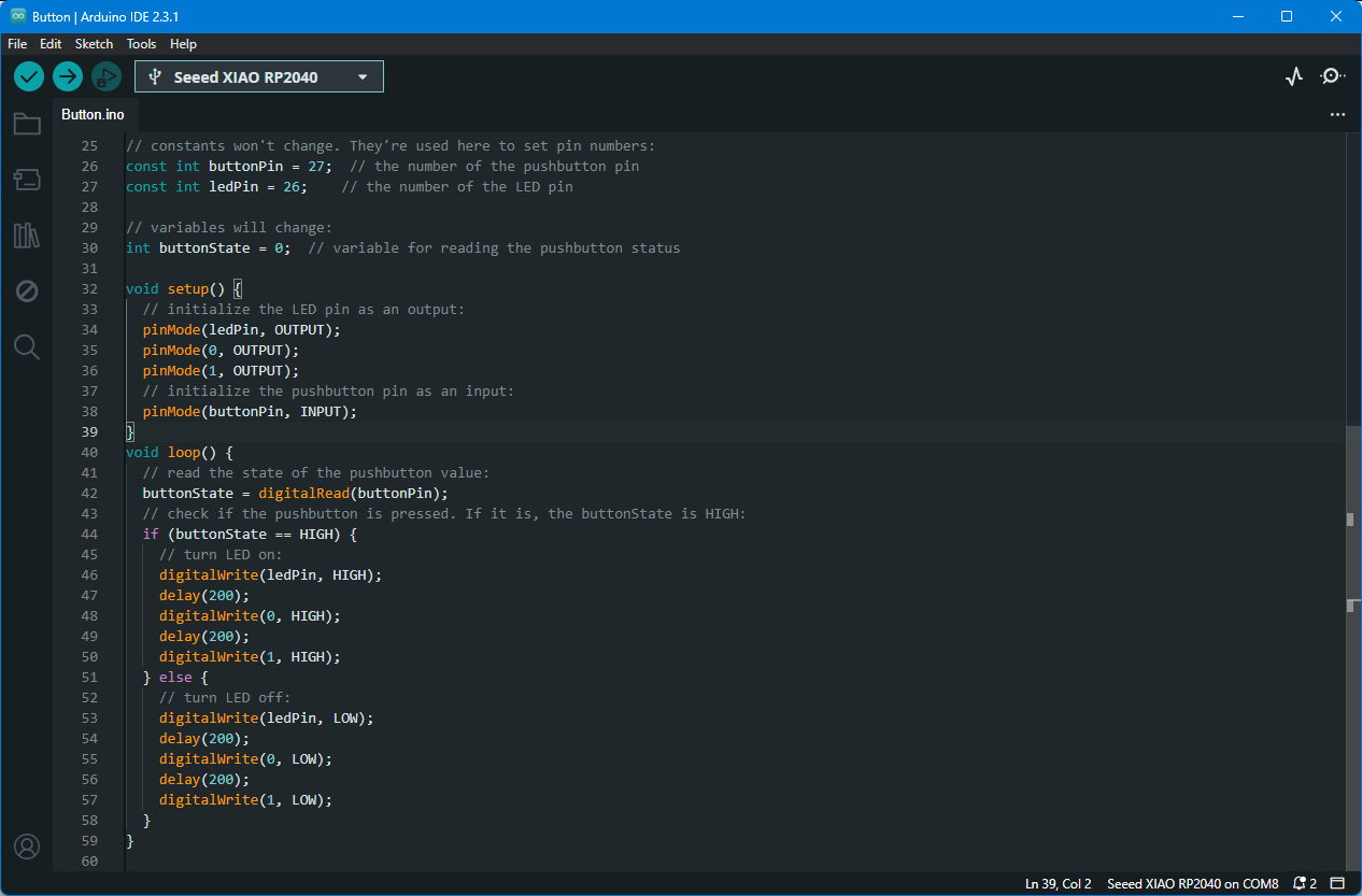 Here is the result!
Here’s the selectable code in case someone needs to try it.
// constants won't change. They're used here to set pin numbers:
const int buttonPin = 27;  // the number of the pushbutton pin
const int ledPin = 26;    // the number of the LED pin

// variables will change:
int buttonState = 0;  // variable for reading the pushbutton status

void setup() {
  // initialize the LED pin as an output:
  pinMode(ledPin, OUTPUT);
  pinMode(0, OUTPUT);
  pinMode(1, OUTPUT);
  // initialize the pushbutton pin as an input:
  pinMode(buttonPin, INPUT);
}
void loop() {
  // read the state of the pushbutton value:
  buttonState = digitalRead(buttonPin);
  // check if the pushbutton is pressed. If it is, the buttonState is HIGH:
  if (buttonState == HIGH) {
    // turn LED on:
    digitalWrite(ledPin, HIGH);
    delay(200);
    digitalWrite(0, HIGH);
    delay(200);
    digitalWrite(1, HIGH);
  } else {
    // turn LED off:
    digitalWrite(ledPin, LOW);
    delay(200);
    digitalWrite(0, LOW);
    delay(200);
    digitalWrite(1, LOW);
  }
}
Conclusion
This week was an interesting experience because I remembered how I struggled with programming in 2020, and now it has become easier. This year I blinked leds with the push of a button. I wanted to go a bit deeper during this embedded programing week, to get better understanding in controling stuff. But I am confident I will push my basic programming skills further in the following weeks.