Networking and Communication
This week is about communication protocols.
notes + video
This week’s class had a lot of new information, so it was quite difficult for me to follow everything. I had to finish most of this week without a lab, so I used TinkerCAD simulation to learn. Later in FabLab SP, I designed and made dedicated boards to complete requirements.
Page Summary
- Basics
- Serial vs Parallel Communication
- SPI protocol
- UART
- I2C
- Design files
- Links
1. Basics
Why Network?
1. Location
2. Parallelism
3. Modularity
4. Interference
To understand basics of communication protocols, this basics of protocols series on circuitsbasics.com was very useful. For effective communication between electronic devices, they need to use the same language. This language is called communication protocol. Some basic protocols are SPI, I2C and UART. These are generally slower than protocols like USB, ethernet, bluetooth and wifi, but are ideal for communication between microcontrollers and sensors where the large amounts of high-speed data does not need to be transferred.
Since I do not have access to a lab or a lot of inventory right now, I chose to understand wired communication protocols - SPI & I2C, with Arduino Unos that I do have access to. When I’m in the lab, or get more access to parts, I want to learn about the other wireless protocols too.
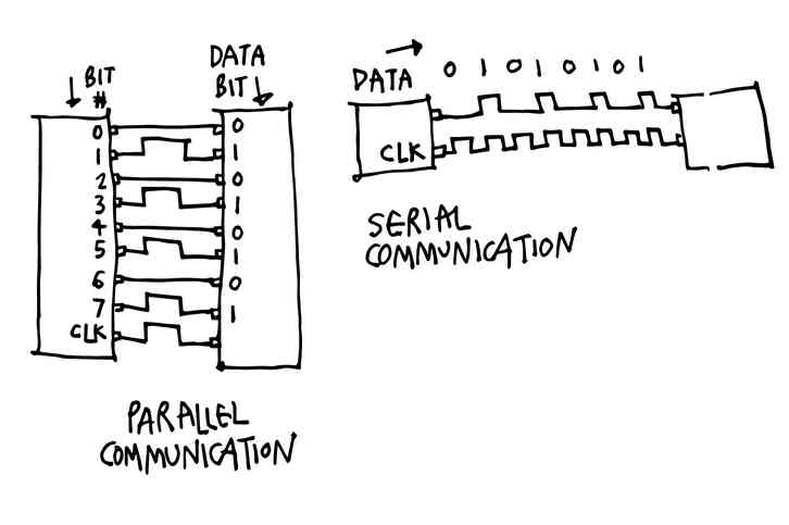
2. Serial vs Parallel Communication
While communicating, bits are transferred from one device to another by quick changes in voltage. In a 5V system, O corresponds to 0V and 1 corresponds to 5V voltage. In parallel communication, multiple bits are transferred at the same time through different wires. Whereas in series, the bits are transferred one after the other through the same wire. The following diagram shows the difference between the two.
3. SPI protocol
Serial-Peripheral Interface (SPI) is a common communication protocol used by many devices like SD card modules, RFID card reader modules. Unlike the other protocols (I2C and UART), SPI does not transfer data in packets. This means that any number of bits can be sent or received in a continuous stream without interruption in transmission.
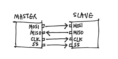
Devices communicating via SPI are in a master-slave(secondary) relationship. The master is the controlling device (usually a microcontroller), while the slave (usually a sensor, display, or memory chip) takes instruction from the master.
This communication needs 4 lines:
MOSI (Master Output/Slave Input) – Line for the master to send data to the secondary.
MISO (Master Input/Slave Output) – Line for the secondary to send data to the master.
SCLK (Clock) – Line for the clock signal.
SS/CS (Slave Select/Chip Select) – Line for the master to select which secondary to send data to.
Basic properties:
4 wires used
10 Mbps maximum speed
Synchronous (devices share clock) & serial communication
1 master can talk to (theoretically) unlimited number of secondaries
How it works:
The clock signal synchronizes the output of data bits from the master to the sampling of bits by the slave. One bit of data is transferred in each clock cycle, so the speed of data transfer is determined by the frequency of the clock signal. SPI communication is always initiated by the master since the master configures and generates the clock signal.
The clock signal in SPI can be modified using the properties of clock polarity and clock phase.
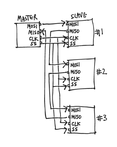
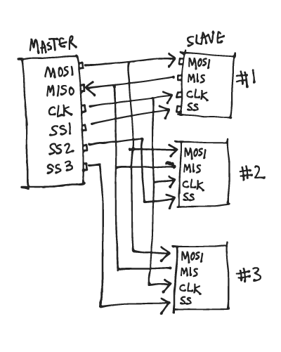
The master can choose which secondary it wants to talk to by setting the Slave Select/Chip Select line to a low voltage level. In an idle non-transmitting state, the SS line is at a high voltage level. Multiple CS/SS pins may be available on the master, which allows for multiple slaves to be wired in parallel. If only one CS/SS pin is present, multiple slaves can be wired to the master.
The master sends data to the secondary bit by bit, in serial through the MOSI line. The secondary receives the data sent from the master at the MOSI pin.
- The master outputs the clock signal first.
- The master switches the SS/CS pin to a low voltage state, which activates the secondary.
- The master sends the data one bit at a time along the MOSI line. The secondary reads the bits as they are received.
- If a response is needed, the secondary returns data one bit at a time to the master along the MISO line. The master reads the bits as they are received.
4. UART protocol
Universal Asynchronous Receiver/Transmitters (UART) are good to connect GPS modules, Bluetooth modules, and RFID card reader modules to Raspberry Pi, Arduino, or other microcontrollers.
Unlike SPI and I2C, UART is not exactly a communication protocol, but a physical circuit in a microcontroller, or a stand-alone IC. A UART’s purpose is to transmit and receive serial data.

It only uses two wires to transmit data between devices asynchronously, meaning there is no clock signal to synchronize the output of bits from the transmitting UART to the sampling of bits by the receiving UART. Instead, the transmitting UART adds start and stop bits to the data packet being transferred. These bits define the beginning and end of the data packet so the receiving UART knows when to start reading the bits. This reading is done at a specific frequency known as the baud rate. Baud rate is a measure of the speed of data transfer, expressed in bits per second (bps). Both UARTs must operate at about the same baud rate.

Basic properties:
4 wires used
115200 maximum baud, avg is 9600 baud
Asynchronous (without clock) & serial communication
1 master and 1 secondary

How it works:
Start bit When the receiving UART detects the high to low voltage transition, it begins reading the bits in the data frame at the frequency of the baud rate.
The data frame contains the actual data being transferred.
Parity describes the evenness or oddness of a number. If data has changed during transmission by electromagnetic radiation, mismatched baud rates, or long distance data transfers. 0 for even and 1 for odd, when the parity bit matches the data, the UART knows that the transmission was free of errors.
To signal the end of the data packet, the sending UART drives the data transmission line from a low voltage to a high voltage for at least two bit durations in the stop bit.
5. I2C protocol
Inter Integrated Circuit (I2C) communication allows for a single or multiple masters (unlimited) to talk to a single or multiple secondaries (max. 1008). It uses two wires to transmit data between devices. Since it follows series communication, it transfers bits one by one through the same wire.
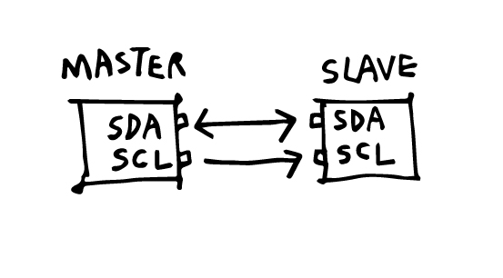
SDA (Serial Data) - to send as well as receive data between the master/s and secondary/s
SCL (Serial Clock) - sends the clock signal
The clock signal is controlled by the master, and the data is synchronized to the bit sampling.
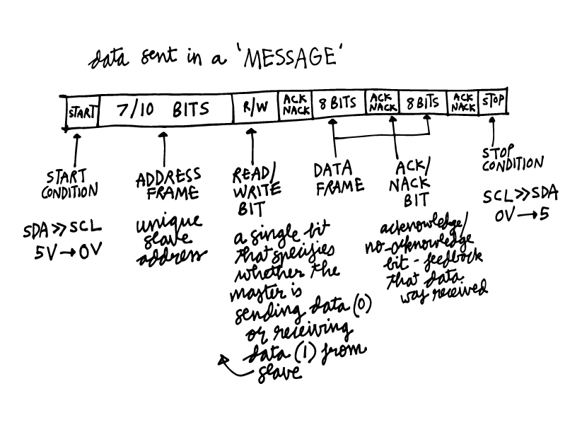
Data is sent in messages. Here is a diagram of the structure of a message.
A pull-up resistor needs to be connected from the Master’s SDA and SCL each to VCC, if there are more than one secondaries or more than one masters.
Since I have access to some Arduino Unos, I tried this guide on Instructables to explore the communication between varying numbers of masters and secondaries.
Arduino Uno has I2C pins:
A5 is SCL
A4 is SDA
as shown in this Arduino pinout diagram by pighixxx.

I2C with one master and one secondary
Reference: Arduino + I2C
Hardware required:
2x Arduino Unos
Hook-up wires
Circuit:
Using the pinout, I first made the circuit with these steps:
1. Connected GND of both Arduinos.
2. Connected analog pin A5 to A5 (SCL) and analog pin A4 to A4 (SDA).
3. Powered up both Arduinos by connecting them to my computer, and setting the boards ands ports for both.
Code:
Master Code
Secondary Code
On opening the serial monitor, you can see messages sent from one to the other:
I2C with multiple masters and secondaries.
Hardware required:
3x Arduino Unos
Hook-up wires
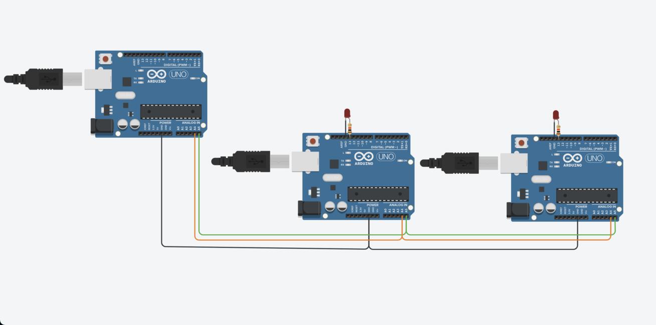
Circuit:
Using the pinout, I first made the circuit with these steps:
1. Connected GND of all Arduinos.
2. Connected analog pin A5 to A5 (SCL) and analog pin A4 to A4 (SDA).
3. Powered up all Arduinos by connecting them to my computer, and setting the boards ands ports for both.
Code:
Master Code
Secondary Code
On opening the serial monitor, you can see messages sent from one to the other:
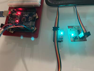
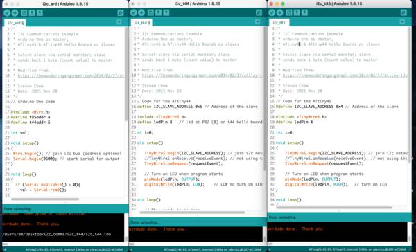
I did the same think with Arduino Uno as master and the hello board based on t44 I made for elec design as the secondary.
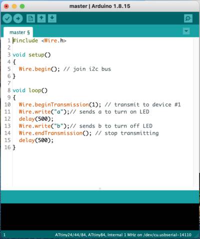
This is the code for the master (Uno):
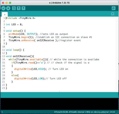
This is the code for the secondary (t44):
You can find the source codes here - Master & Secondary
Basically the master send signals ‘a’ and ‘b’ to the secondary every 0.5sec. LED turns on and off…
I2C with one master (Arduino Uno) and multiple secondaries (1 ATtiny 44 and 1 ATtiny 45)
I used this guide to send messages between one master and 2 secondaries.
Reference: This documentation is a good guide I used as a reference. I modified it for an attiny44 and attiny45 that I used.
First step is to download the ATtiny i2c slave library. You can find this here.
Upload this master code to the Arduino Uno.
Upload this attiny44 secondary code to the attiny44. I did this with the FabISP.
Upload this attiny45 secondary code to the attiny45. I did this with the FabISP.
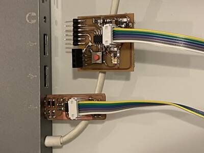
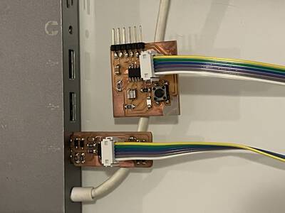
Next, connect the full circuit.
Match the ISP headers of the 2 secondaries in serial through one single cable and match with the GND, VCC, SDA and SCL on Arduino Uno, like so:
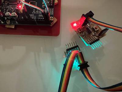
Open the serial monitor from the master’s serials port. On sending a ‘4’, the master addresses the t44 and on sending a ‘5’ it addresses the t45. The secondaries both return a count of the number of times they are each pressed.
I also want to try and make a MQTT network at some later time.

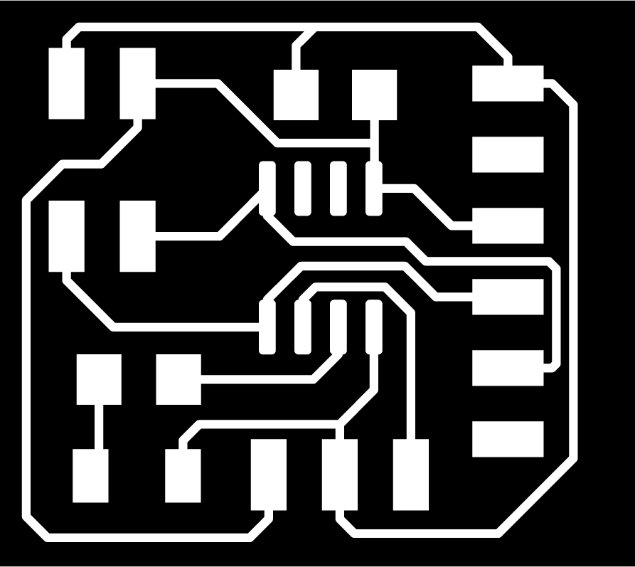
6. Design files
Bridge:
schematic
traces
outline
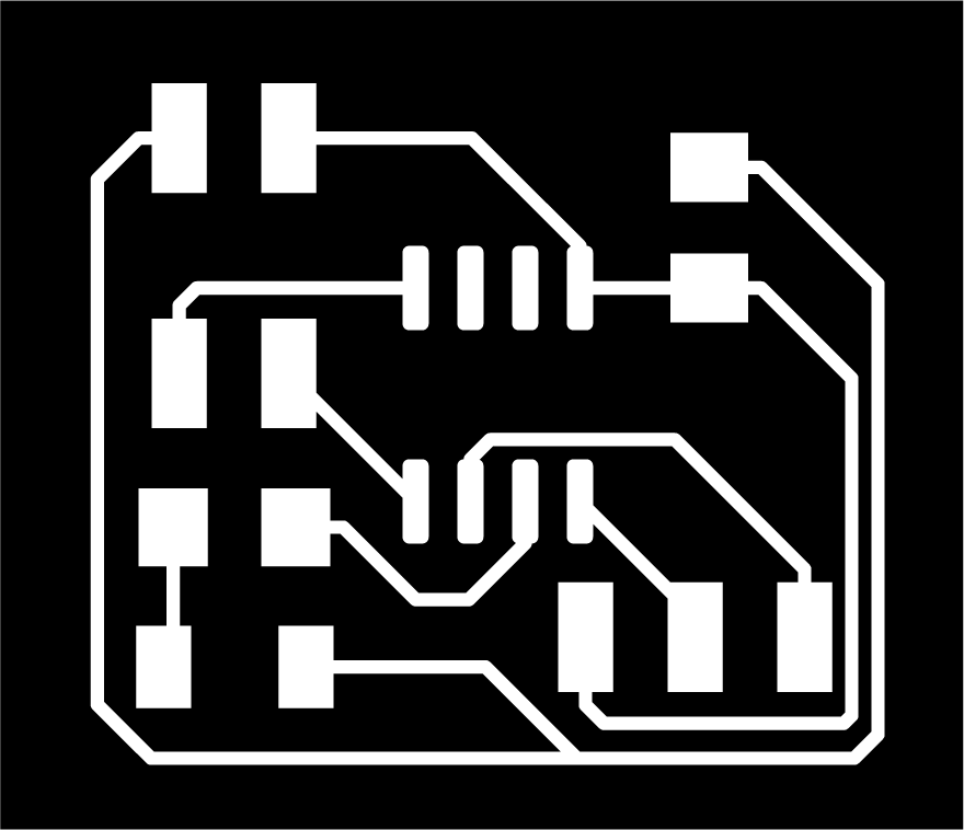
Node:
schematic
traces
outline
I2C with one master (Arduino Uno) and multiple secondaries
Code for Master
Code for t44 Secondary
Code for t45 Secondary
7. Links
Arduino I2C and multiple slaves tutorial
Basics of protocols series on circuitsbasics.com