Input Devices
I did this week without lab access due to CoVid lockdown restrictions.
This week, I used an Arduino board to read an analog temperature sensor.
When I have access to a lab, I will make a microcontroller board with a sensor as input.
Page Summary
- Inputs using Arduino board (no lab access)
- Probing an input device’s analog levels and digital signals
- Designing a micro-controller board to read input
- Milling, Stuffing and testing
- Programming
- Reading the input
- Design Files
- Important and Interesting Links
1. Inputs using Arduino board (no lab access)
I wanted to start with a simple project to get the basics right and understand fundamentals of using inputs with microcontroller board. Using an Arduino Uno board with it’s documentation was very basic. So I did this befordesigning my own board.
For reference, I used the Arduino Project 3 ait used the temperature sensor.
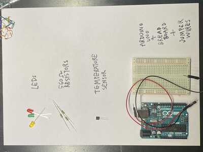
I started by collecting all the components.
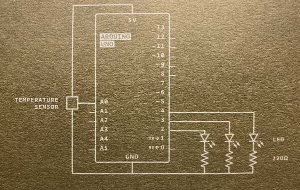
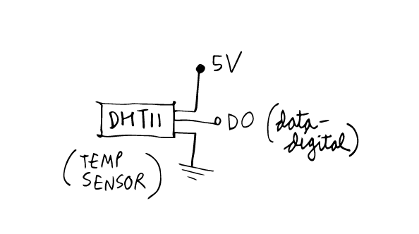
I used this schematic to connect everything.
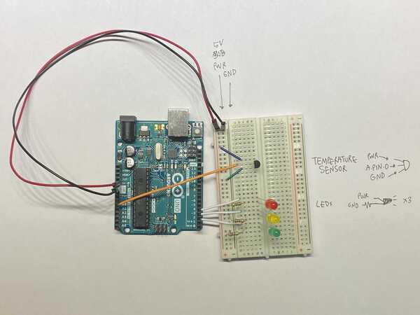
The circuit setup was fairly easy. This is how it looks.
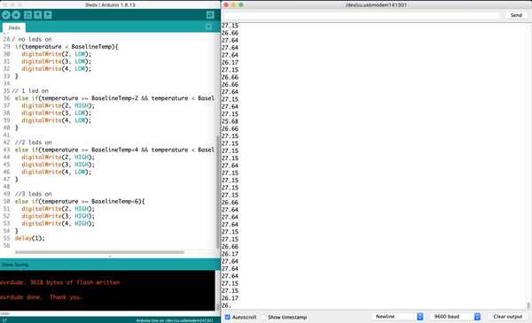
At first, all lights were continuously on. I checked the serial monitor and saw that the temperature was around 2degrees without touching. So I adjusted the baseline temperature to 25 in the sketch. After some trial and error, adjusted the sketch so that on touching it lightly for about 5 seconds, the second led lit up and on holding it tighfor some seconds the third led lit up. The serial monitor indicated temperature range from 26-32 degrees.
So an increment of 2-4-6 degrees worked out perfectly.
This is it in action:
The code was fairly simple as well. You can find it here - Sketch
Understanding the basics:
      // defining constants
      const int SensorPin = A1;                   // analog template input from temp sensor
      const float BaselineTemp = 25.0;            // reference temp defined

      // serial port on and setup runs once
      void setup(){
        Serial.begin(9600);                                        // serial monitor baud rate
        for(int pinNumber = 2; pinNumber<5; pinNumber++){          // for all pins 2, 3 and 4 connected to leds
          pinMode(pinNumber,OUTPUT);                               // define them as output
          digitalWrite(pinNumber, LOW);                            // leds off by default
        }
      }

      // loop - read sensor input
      void loop(){
        int sensorVal = analogRead(SensorPin);                      // read analog value from temp sensor

      // serial monitor output - temperature
        float voltage = (sensorVal/1024.0) * 5.0;                   // calculate voltage from temp sensor value
        float temperature = (voltage - .5) * 100;                   // calculate temperature from voltage
        Serial.println(temperature);                                // print temperatue on serial monitor


      // no leds on
        if(temperature < BaselineTemp){                             // defining relation between input temp and reference
          digitalWrite(2, LOW);
          digitalWrite(3, LOW);
          digitalWrite(4, LOW);
        }

       // 1 led on
        else if(temperature >= BaselineTemp+2 && temperature < BaselineTemp+4){
          digitalWrite(2, HIGH);
          digitalWrite(3, LOW);
          digitalWrite(4, LOW);
        }

        // 2 leds on
        else if(temperature >= BaselineTemp+4 && temperature < BaselineTemp+6){
          digitalWrite(2, HIGH);
          digitalWrite(3, HIGH);
          digitalWrite(4, LOW);
        }

        // 3 leds on
        else if(temperature >= BaselineTemp+6){
          digitalWrite(2, HIGH);
          digitalWrite(3, HIGH);
          digitalWrite(4, HIGH);
        }
        delay(1);                                                    // delay 1/100 sec before starting loop again
      }
2. Probing an input device’s analog levels and digital signals
To probe an input’s signal, I used a joystick as a potentiometer and measured the voltage level across GND and the analog pin. At the neutral position, the voltage difference is 2.5 V and moving it to one extreme it becomes 5V (full VCC) and on the other side 0V. The video shows this:
I use an Arduino and connect one of its digital output pins to the oscilloscope. I’m set it to light an LED, at 50% brightness attached the Oscilloscope’s probe to the pin and ground respectively.
On connecting the two probes, it shows a square wave like so:
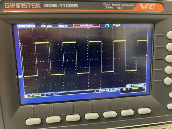
This indicates that by outputting zero volts for a period of time, followed by a specific voltage such as 5 volts for the same period of time, the led lights.
When I do the same using the joystick, it shows me a flat wave like so:
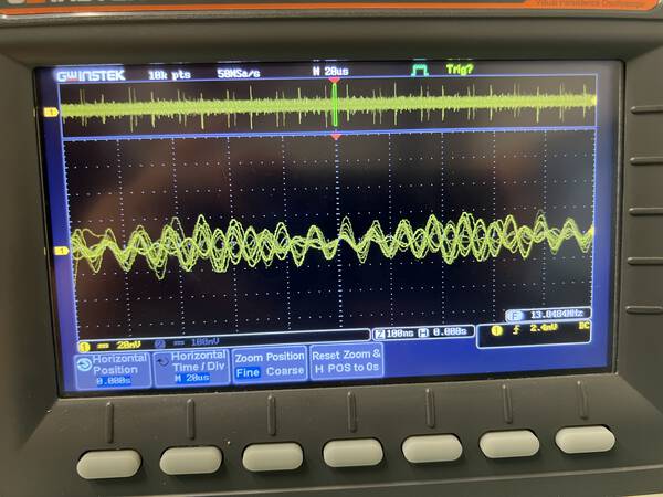
I also tried getting an analog signal using the oscilloscope but coudnt get it very clear:
3. Designing a micro-controller board to read input
For this week, I want to try measuring light color using a RGB colour sensor.
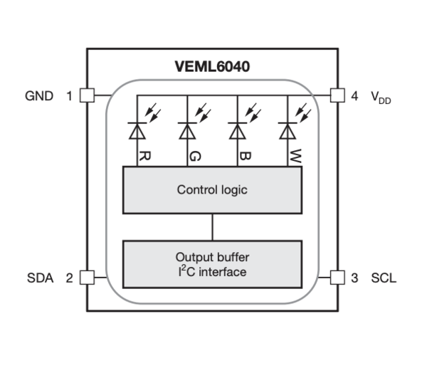
First task is to select a microcontroller for the selected sensor. By looking at the datasheet and pinout of the sensor VEML6040, it needs only SDA and SCL to be connected by I2C communication protocol. The SDA needs a pull-up resistor.
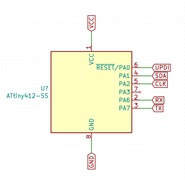
The microcontroller itself needs to Tx, RX to be able to connect through UPDI to a programmer.
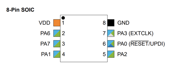
I choose the Attiny412 so I can use the i/o pins and connect the colour sensor through I2C.
ATtiny412 Datasheet
VEML6040 - RGBW Color Sensor with I2C Interface
Downloaded the footprint from here
Installed the symbol and footprint on KiCAD using this guide
VEML6040 library
I follow the design process described in Electronics Design week to design and the process in Electronics Production Week to create the toolpaths. I will fabricate this when in the lab.
VEML6040 colour sensor pinout:
ATtiny412 pinout:
Pins used:

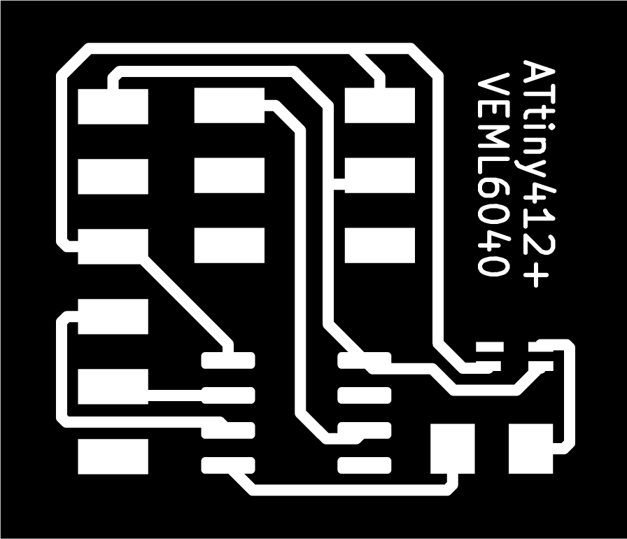
412 schematic:
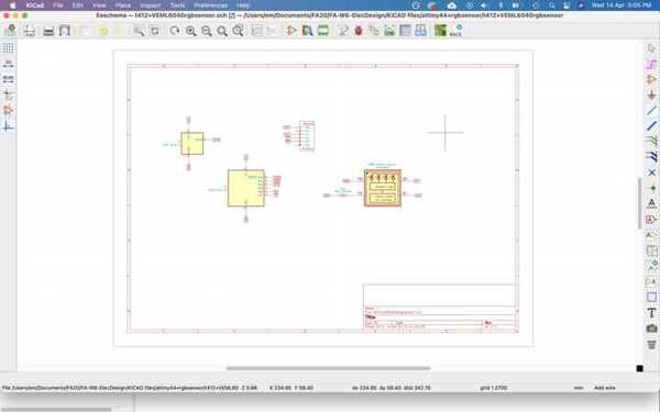
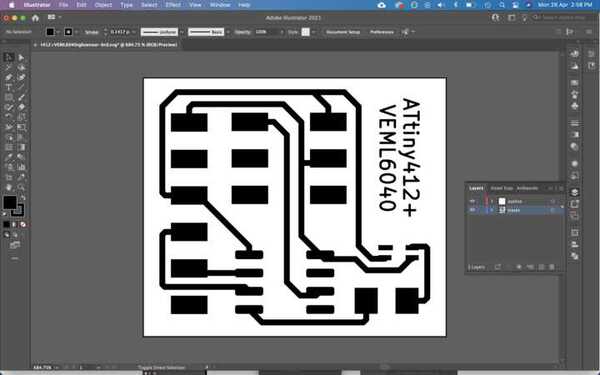
KiCAD schematic:
Separating layers in Ai:
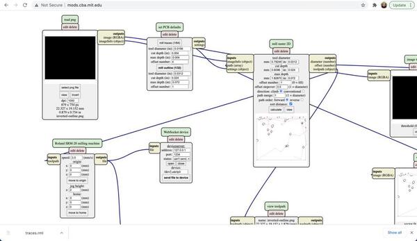
Importing png and creating toolpaths in mods:
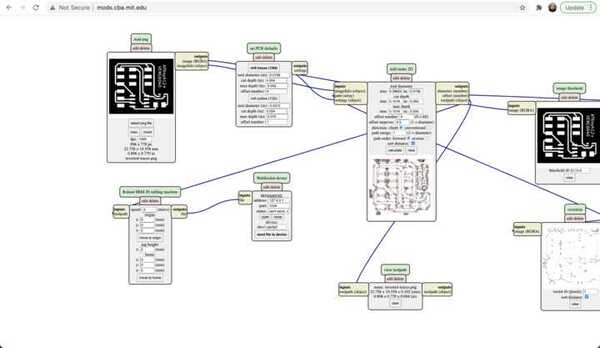
There are weird dots in the toolpath, so I redo it in FabModules.
For my final project, the Aeroborator, I want to use a temperature sensor and a potentiometers as inputs.
DHT11 - temperature and humidity sensor
Phototransistor - to measure ambient light intensity
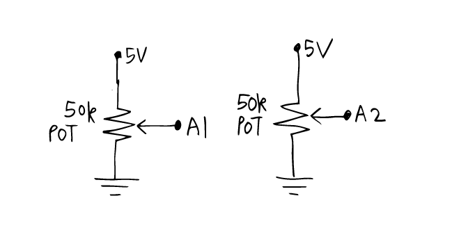
Potentiometer / variable resistance - to control flow of water through pump
Potentiometer / variable resistance - to control grow light intensity
So I start by checking all pinout for individual devices.
I use the Phototransistor in active mode - meaning the output of the transistor is proportional to the intensity of the light.
![]()
The potentiometers have 3 pins - one for power, one GND and third data that connects to the MCU.
The temperature and humidity sensor DHT11 has 3 pins - 5V power, GND and data which connects to a digital pin of the MCU.
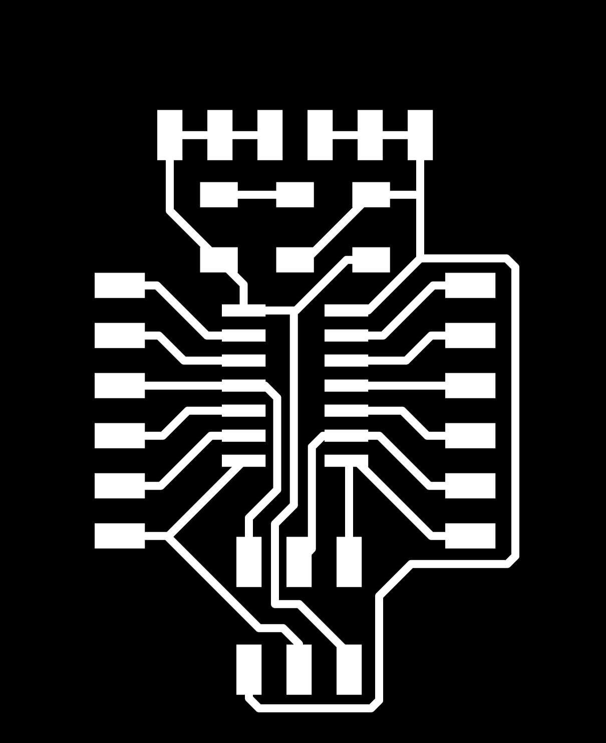
So I use KiCAD to make the schematic. The inputs and power requirements can be found on the Project Development page.
After making the traces in the pcbnew section, I exported the svg, opened it in Ai and here are the traces and outline.
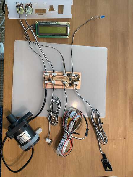
I made the pcb according to the workflow described in electronics production week and tested it and programmed it.

Here is a picture of all inputs with some additional outputs included.
5. Programming
6. Reading the input
7. Design Files
For ATtiny412+VEML6040 board:
Traces png
Outline png
Schematic pdf
Schematic file
Toolpath for Roland
Kicad pcbnew
For ATtiny84 input-output board:
Traces png
Outline png
Schematic pdf
Eagle files
Toolpath - traces
Toolpath - outline