Embedded Programming
This week is about learning how to program a microcontroller.
Page Summary
- Understanding a Datasheet
- Comparing the performance and development workflows for different microcontroller families
- Programming with FabISP + Arduino IDE
- Programming with avr-gcc
- Programming with Atmel Studio
- Code files
1. Understanding a Datasheet
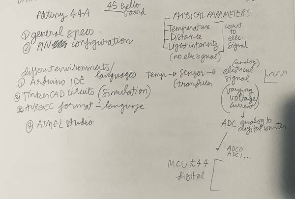
For Electronics Design, I modified the hello.ftdi.44 board by adding a pushbutton and an led. This board uses the Attiny44A, so I chose the same datasheet to understand it better.
The datasheet is available on the Atmel site. The document contains the main features of the MCU, the pinout diagram, architecture overview, register summary, assembly instruction set and packaging information, and describes the microcontroller features in detail.
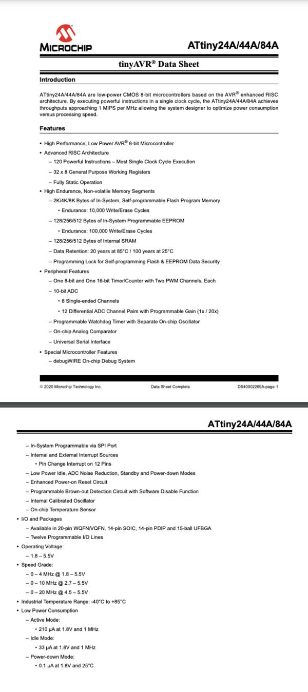
This main features page gives a lot of information about the microcontroller. It comes in 3 versions - the ATtiny24A, ATtiny44A and ATtiny84A. They all have the same architecture and feature set, but different amounts of flash memory.
You wan write/erase it 10,000 times.
After programming it can retain the data for 20 years at 85 degC and 100 years at 25 degC.
It has two PWM channels - it can be used to make analog signals into digital.
It also lists the peripherals, such as timer/counters, ADCs, analog comparators and serial interfaces.
The IC is available in different packaging- ranging from 14-pin SOIC or PDIP to 20-pin VQFN.
There are 12 programmable I/O lines on the MCU and it can operate with supply voltages from 1.8 - 5.5V, with operation at higher frequencies requiring higher supply voltages.
In all, it allows for optimisation of power consumption versus processing speed.
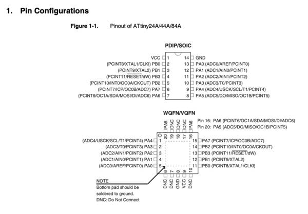
The most useful is the pinout of the MCU. Depending on the packaging, it helps design a PCB. It is important to note that all pins have multiple characteristics, so depending on the project, one can chose which pins to use for particular tasks.
The default pins are VCC (supply voltage) and GND (ground).
Port B (PB3:PB0) - is a 4-bit bi-directional I/O port with internal pull-up resistors.
PB3 has the RESET capability
Port A (PA7:PA0) - A is a 8-bit bi-directional I/O port with internal pull-up resistors. Port A has alternate functions as analog inputs for the ADC, analog comparator, timer/counter, SPI and pin change interrupt.
The first three chapters - pin configurations, overview and general information, cover most of the information in brief. The erst of the chapters talks in detail about CPU core, memories, clock system, power management, system control, interrupts, I/O ports, timer/counter with PWM, universal serial interface for communication, analog comparator, analog to digital converter and other peripheral information.
2. Comparing the performance and development workflows for different microcontroller families
Next task is to program the board you have made to do something, with as many different programming languages and programming environments as possible.
Some different architectures:
1. CPU architecture - t44 series uses ISP programmer, t412 series uses UPDI programmer / serial pyupdi.py
2. SAMD11 series uses JTAG programmer with ARM core / USB
3. ESP8266 series + ESP32 series use Tensilica 32-bit
4. BBC microbit - ARM core / serial FTDI/USB
5. Raspberry Pi - broadcom system / serial USB
Pi Pico - ARM
Here is how a development workflow generally is:

Comparing basic features of different microcontrollers:
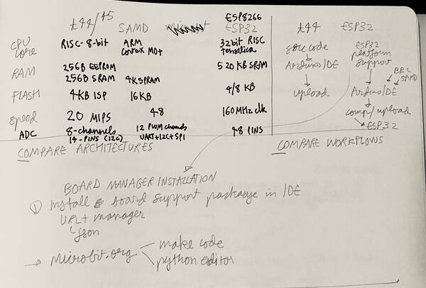
This helps while selecting the appropriate MCU for particular tasks depending on the features, communication protocols, inputs and outputs.
Different environments possible for an attiny88/84:
In the next sections I will use different workflows for programming the hello board based on t44 I made in Electronics Design week.
3. Programming with FabISP + Arduino IDE
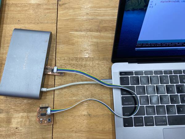
For this task I will use my hello-board I made in Electronics Design week with an added led and pushbutton and program it using the FabISP I made in Electronics Production week in the Arduino IDE. I connect the hello board to the FabISP using a ribbon cable in the correct orientation. And the plug in the FabISP into a USB hub connected to my computer running a MacOS Big Sur.
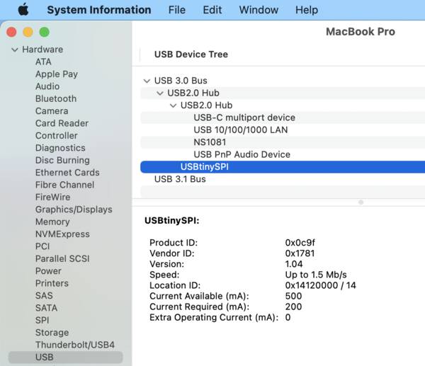
To check if the FabISP is connected properly, check that the computer recognises it when you plug it in.
Apple drop-down > About this mac > System Report > Hardware > USB, it should show a USBtinySPI like in the picture.
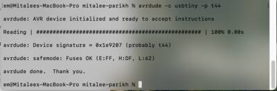
Second task, to check that the hello board is recognised, open Terminal and type in
avrdude -c usbtiny -p t44
It will initialize the AVR device, check fuses, and show the device signature address. This address is used for I2C or tother communication.
In the Arduino IDE software, the first task is to add in the URL for the ATtiny support in the “Additional Boards Manager URLs” in File > Preferences, then go to “Boards Manager…”, look for the URL for ATtiny and install it. This will add the attiny familt to the drop-down for boards.
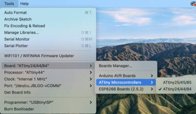
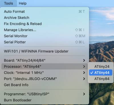
Next select the processor:
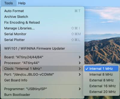
Then select either the internal 1MHz or internal 8MHz clock, according to what we found earlier by reading the datasheet.
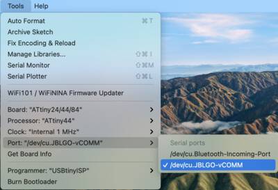
Next select the Port, this is the computer port to which the ISP is plugged in.
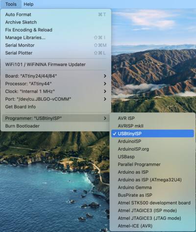
Selct programmer as USBtinyISP, because the FabISP is going to program the hello board.
Now, write a code or open one from the Examples, define pins. Compile and upload using the programmer. If you change the clock, burn bootloader first.
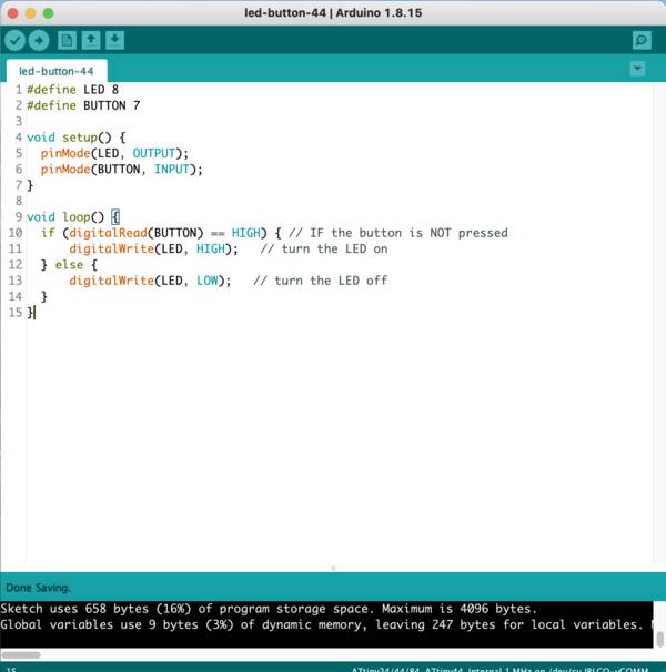
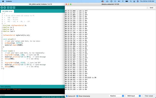
I wrote a simple program to operate the led using the pushbutton.
Next to read serial communication, I modified the code, to digitalRead and show indication of the state of the LED - ON or OFF.
For this after uploading the code using the FabISP, it needs to be removed and connected using an FTDI. This allows the serial communication to return to the Arduino IDE monitor. The FTDI also provides the power. So it basically connects - VCC, GND, TX, RX of the hello board to the FTDI board.
TX (hello) and RX(FTDI board) are connected and RX (hello board) to TX (FTDI board) are connected.
Basically when one transmits, the other receives.
FTDI is the protocol for communication. It can be connected in various ways:
-
Through a commercial board like this:
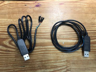
-
Through a cable like this:
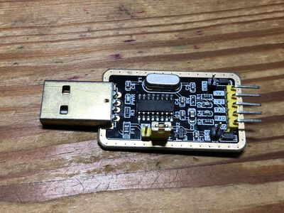
-
Through a DIY board like this:
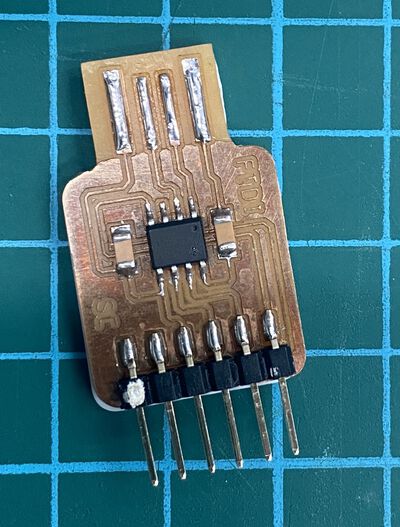
I use a DIY board I borrowed from Steven.
You can use this schematic to make a ftdi board.
I also attempted at making my own using Stevens simple design.
Traces:
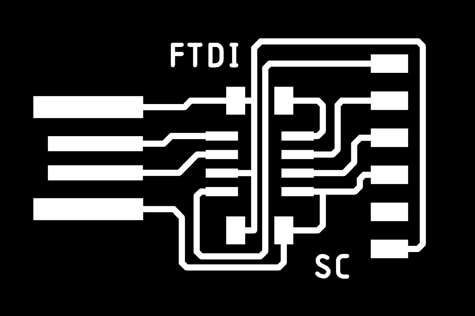
Outline:

I used a t45 based hello board as well.
So after uploading the blink code + serial, connect the ftdi board to hello board, and on opening the serial monitor, it should show the status of the LED.
4. Programming with avr-gcc
I used Arduino IDE and the same physical setup (FabISP+ribbon cable+ hello board) and wrote the code in avr-gcc. Arduino IDE operates avr-gcc in the background. And has an interface over it. So it works easily.
This is the code file for t45
#include <avr/io.h>
#include <util/delay.h>

const int led=PB4;
const int sw=PB3;

 int main(){
  DDRB |= (1<<led);
  DDRB &= ~(1<<sw);

  while (1){
    if (!(PINB & (1<<sw)))
      PORTB |= (1<<led);
    else
      PORTB &= ~(1<<led);
  }
 }
and for t44 with the makefile.
#include <avr/io.h>
#include <util/delay.h>
// #define F_CPU 1000000UL     // 1 MHz internal RC

int main(void){
    DDRB |= 1<<PB2;     // set PB2 as output
    PORTB |= ~(1<<PB2); // turn LED off

    while (1){
        PORTB = ~(PINB & (1<<PB2));    // invert LED status
        _delay_ms(1000);    // 1 sec delay
    }
}
Basically you include avr/io and delay libraries so that you can use the arduino commands.
Also, the pin numbers are recognised by their ports PB# instead of pin #.
5. Programming with BBC micro:bit + Make code
The BBC micro:bit is a pocket-sized computer that introduces how software and hardware work together. It has an LED light display, buttons, sensors and many input/output features that, when programmed, let it interact with the world.
Microsoft MakeCode is a free, open source platform for creating engaging computer science learning experiences that support a progression path into real-world programming.
It has a simulator, a block editor and a javascript editor.
To explore a different workflow, I will document the simple workflow to make a digital dice, using a micro:bit and MakeCode.
Basically, on shaking the micro:bit, the accelerometer input triggers the creation of a random number between 1 and 6 and displays it on the LED grid output in dots.
First, open the editor(https://makecode.microbit.org/#editor) and select blocks. This is an easy graphical interface, that generates code according to the logic of the blocks arranged.
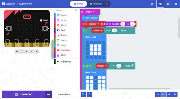
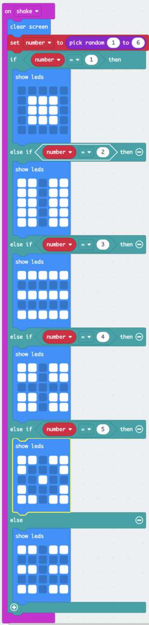
- Define the logic - on shaking the accelerometer is active, first the previous display needs to be cleared, then a random number between 1 and 6 is generated. Corresponding to the number the screen displays the LEDs in the defined graphical pattern. I made some custom patterns for the numbers.
This can also be done using javascript or python.
-
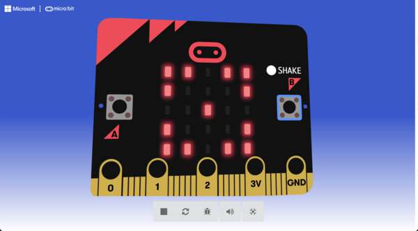
Simulator display To display the effect of the code, you can simulate it on the screen.
-
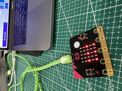
Download hex file and upload onto micro:bit
Instead of compiling and programming, it is as simple as this - downloading the hex and uploading it onto the micro-bit that is connected to the computer through a USB.
-
Done On shaking the dice, it shows the patterns.
Another way to do it through MicroPython. This BBC micro:bit MicroPython documentation is very good.
Mu is another Python code editor.
- Programing ESP32 with MicroPython(https://micropython.org/) on Wokwi(https://wokwi.com/)
MicroPython is a lean and efficient implementation of the Python 3 programming language that includes a small subset of the Python standard library and is optimised to run on microcontrollers and in constrained environments.
Wokwi is an online simulator for Electronics. You can create and run MicroPython projects on Wokwi.
https://readthedocs.org/projects/micropython-on-wemos-d1-mini/
Guide to Install Tools to Program in Micropython on the ESP32 on MacOS X
Setup:
1. Download and install Python
2. Install ESP32 Serial Driver
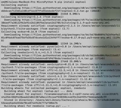
3. Pip Install esptool in terminal
4. Download Micropython Firmware
5. Write Micropython to the ESP32
In terminal.app, change directory to where you downloaded the bin file. In terminal:
7. Code files
Code (sketch) for programming with FabISP + Arduino IDE
avr-gcc blink for t44
avr-gcc blink for t45
Hex file for graphical dice