Final Project
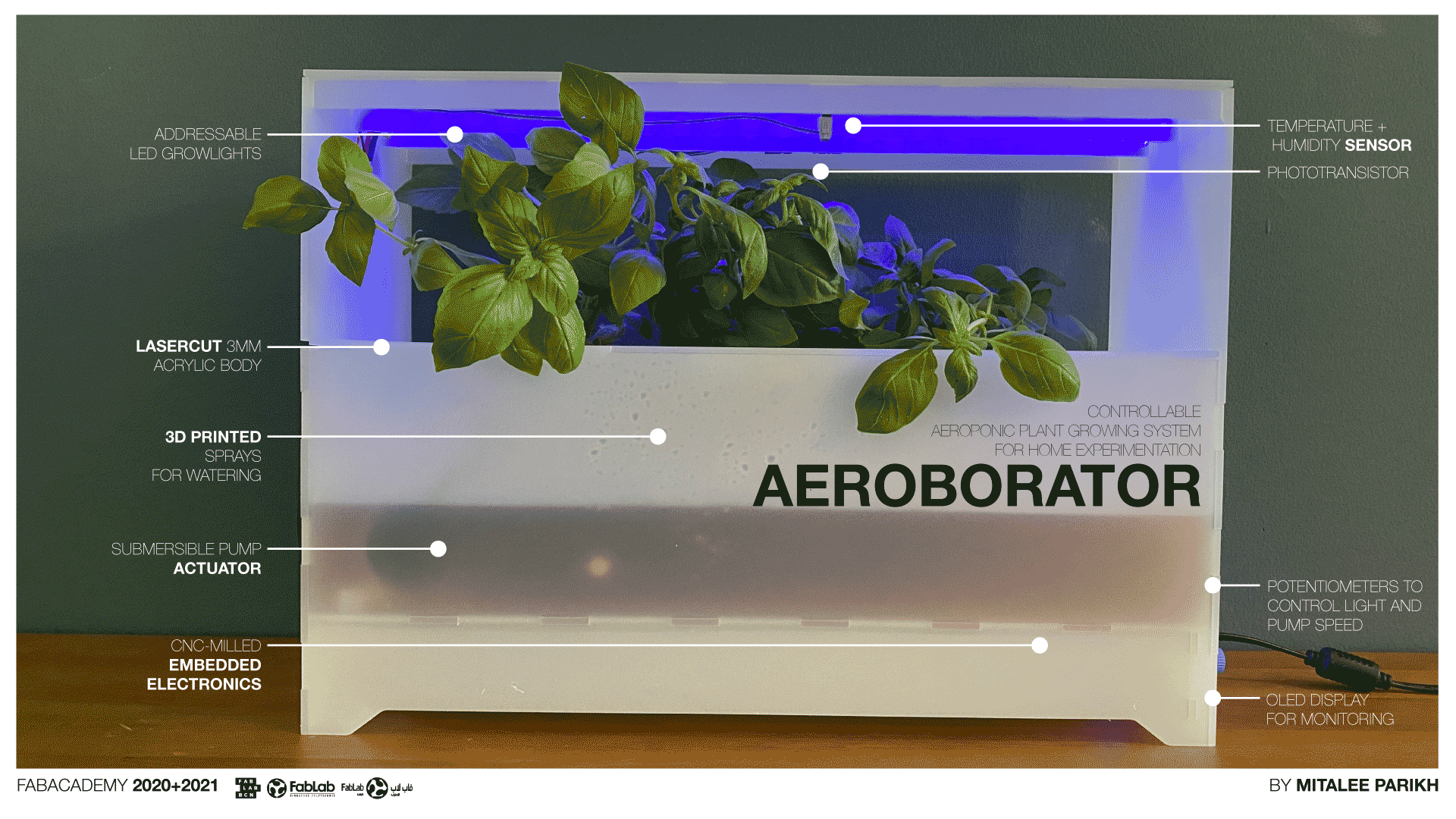
My final project is called the Aeborator - an arborator (one who plants trees) machine that works on principles of aeroponics.
Page Summary
- Project summary
- Presentation links
- Bill of Materials
- Links to pages of parts fabrication
- Design Files
- License
- Acknowledgements
1. Project summary
The Aeroborator is a small table top planter to grow herbs and kitchen garden plants. It uses a sprinkler system to spray a nutrient solution directly on the roots with a water pump from a reservoir. This method doesn’t use any soil and reduces the amount of water used to grow plants. It measures temperature and humidity through a sensor and displays it on an OLED screen. This helps in monitoring the conditions. It also has a light sensor and LED grow lights that use specific UV frequency to enhance the growth of plants. Both the light and the speed of water flow can be controlled with regulators on the side of the machine.
It is made keeping in mind experimentation with parameters like the speed of water flow and the intensity of light. So one can change these settings and work out the conditions that work best for different types of plants.
It is meant to help figure out settings before making a larger scale hydroponics system.
I started by learning what work is already done. Both, for the overall project as well as systems in parts.
There are many commercially available hydroponic growing systems.
Some particular ones I like are:
The modularity and the ease-of-use in the Moltkegarden project.
True garden has extensive information and how-tos for starting a vertical garden.
FARM-X: The First Modular Vertical Farm Concept (Almost) Unveiled
This Modular Vertical Farming projects has an interesting approach to designing a scalable system.
A common project using DHT11 and OLED display to make a Weather station.
And the best reference for everything from a product to a system to developing a community and a business model - Aquapioneers: business integrating product and services for aquaponic farming
I read more about the theoretical aspects of Controlled Environment Agriculture (CEA), basics of homegrown vertical farms, this beginners guide and practices of lighting through the linked sources.
While designing the machine, I kept in mind the integration of all different systems to make a cohesive design since the beginning. The basic tasks and parts of the design and fabrication process included: (not in any particular order)
1. A phototransistor to sense daylight intensity and change brightness of the LED growlight accordingly.
2. A temperature and humidity sensor to measure and display values on an OLED screen.
3. Power schematic with 12V DC, 5V DC converted from AC.
4. Submersible water pump attached to spray heads to spray the roots of plants.
3. Use regulators to control the water flow and light intensity.
5. Acrylic body using laser cut joints, no fasteners and waterproof the tank with silicon sealant.
6. Laser-cut porous pots to hold the growth medium and the plants
7. Growing seedlings of plants and then putting them in the rockwool to grow more.
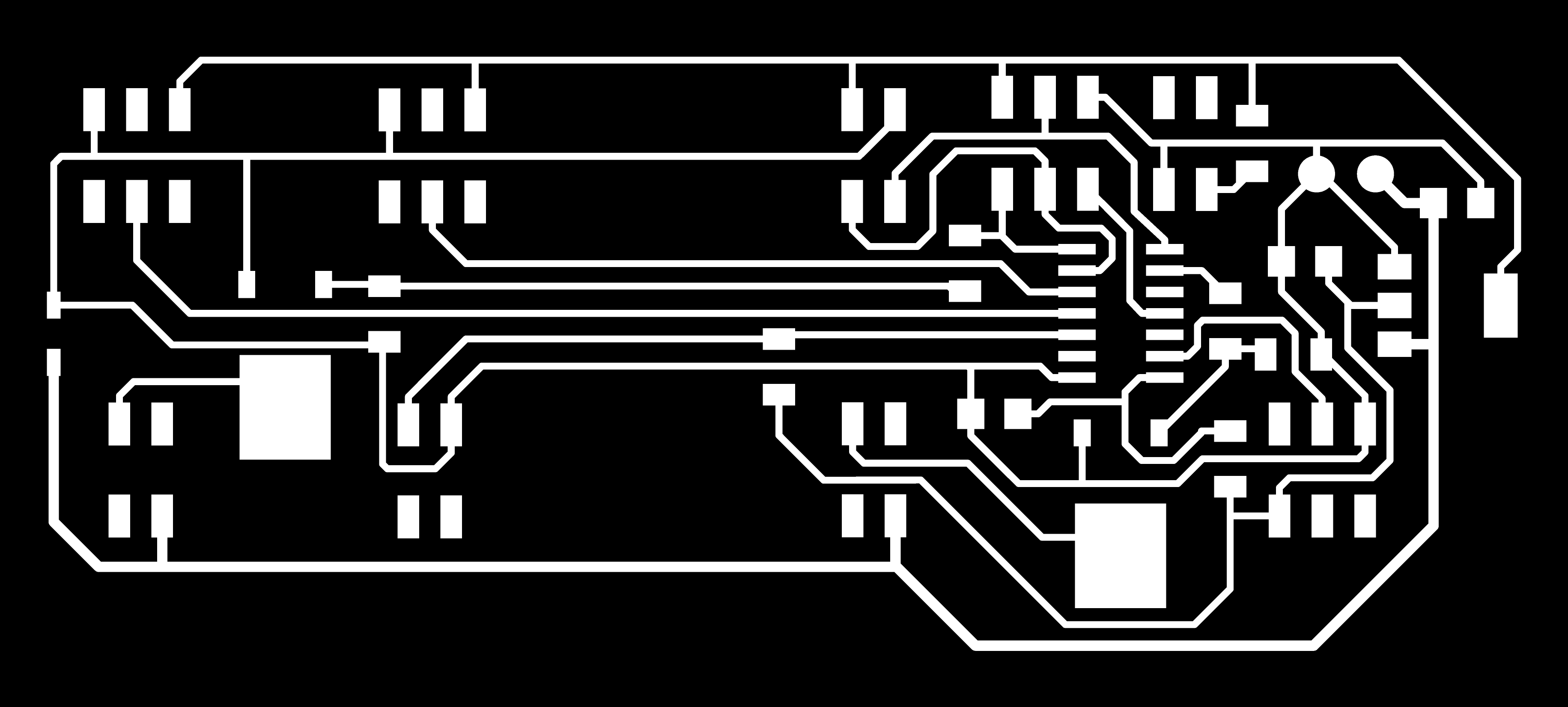
8. Designing the PCB and fabricating it, soldering on components, programming the board and testing inputs/outputs
9. Making a 3D model for planning and extracting 2D cutting files.
10. 3D printing parts
This wasn’t exactly a linear process, I kept going back and forth between tasks to make sure everything integrated cohesively.
The best way to evaluate the project is to successfully grow a plant in it. I made spinach seedlings from seeds and have put them in the machine to grow further. The success will depend on the right temperature, humidity and light conditions.
2. Presentation Links
Presentation slide
Presentation video
3. Bill of Materials
The main body of the machine is made from 3mm acrylic in a frost white finish. Acrylic is not reactive to water, it can be laser cut easily accurately and joints can be waterproof using silicon sealant. It doesn’t react to the nutrient solution in the reservoir. It can be joined without using any fasteners.
I used a FR1 single sided copper sheet to mill the circuit. I then gathered all components and electrical parts from the FabLab UAE’s stock of materials.
I also repurposed a 12V DC water pump from an old project lying around in the lab.
I ordered A SSD1306 OLED screen with I2C, a generic sprinkler system, some spinach seedlings and the nutrient solution online.
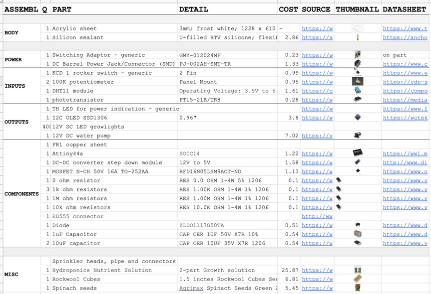
I have added all sources and costs in the Bill of Materials File.
The major parts of the machine are the body and the net pots, the pump and sprinkler system, the electronics including the inputs/outputs, the PCB and wires.
4. Parts fabricated in other weeks
I have answered all questions of the final project requirements in the Applications & Implications page and Project development page, including:
What will it do?
* Who’s done what beforehand?
What will you design?
What materials and components will be used? What parts and systems will be made?
Where will come from? How much will they cost?
What processes will be used?
What questions need to be answered?
* How will it be evaluated?
5. Design Files
Lasercut file - dxf
3D model
PCB project files
PCB traces - png
PCB traces - rml
PCB outline - png
PCB outline - rml
3D printing - stl
3D printing - gcode
Code
6. License
7. Acknowledgements
I would like to thank Steven from FabLab SP, for his continuous guidance and support.
I would like to thank Hashim from FabLab UAE, for letting me use the Lab and it’s resources.
I would like to thank Luciana from FabLab BCN, for letting me continue in the second cycle of FabAcademy in a different location.