Computer controlled machining
This week is about making something big using a CNC milling/routing machine. I want to explore the possibilities of CNC machining - drill, pocket, dog-bones, nesting, etc. I tried to make a versatile furniture piece so that I can use different joints and experiment with them.
Page Summary
- Introduction
- Design
- Nesting
- CAM
- Test settings
- Machining
- Assembly
- References
- Design Files
1. Introduction
Material available for use is a veneer plywood of size 2440 x 1220 x 17 mm.
On checking with a vernier caliper, thickness varies between 16.9mm and 17.1mm. So I’ll use an average of 17mm thickness for my design.
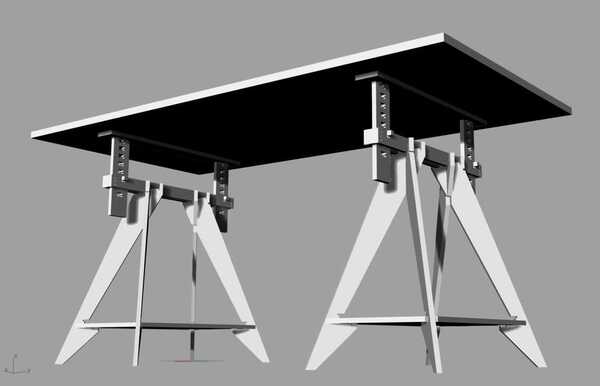
I wanted to make a desk with adjustable height so after some viewing some references, I decided to make trestle legs for a desk setup.
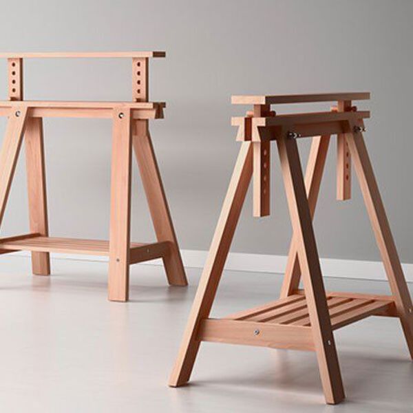
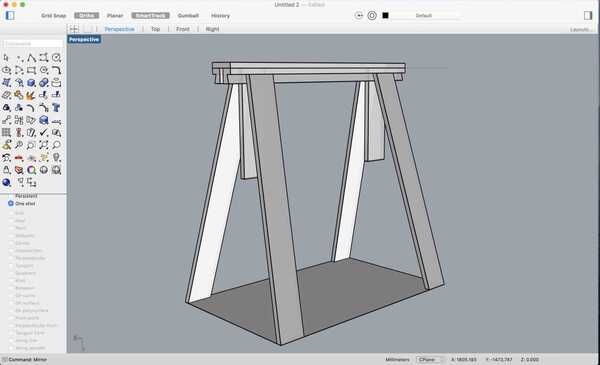
I started by making a 3D version of IKEA’s FINVVARD to understand how it works.
Since, I didn’t have access to the lab during this week, I did the CAM part according to tools used in FabLabBCN.
Later when I used FabLab SP, I did it again using Vcarve Pro.
2. Design
I learnt about some details from the 50 Digital Joints poster. For the group assignment, I made a joint using both profiling and pocketing.
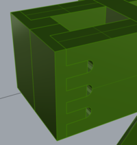
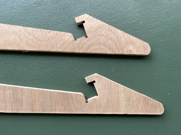
I also made some versions of the finger tennons, lapped finger tennons, throughhole finger tennons to design the trestle.
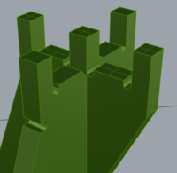
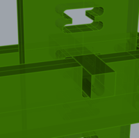
Here is how the final legs look. I need to make 2 of these and put any flat board on top to make a tabletop.
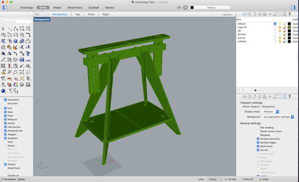
Here it is in 3D.
3. Nesting
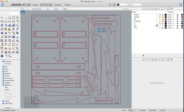
Next, I lay everything flat on the XY plane and did a make 2D. For nesting I used an online service called nestandcut.com to nest all parts in twice the quantity on a sheet of 1220x1220x15 mm. (Half a sheet). I uploaded a dxf file that I export from Rhino and imported the nested dxf back.
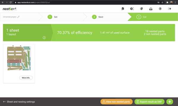
I made some changes manually to fit it all in the available sheet. Like I put two parts insode the big board and nest it within to make more space for the missing parts. Here is what that looks like:
4. CAM
RhinoCAM
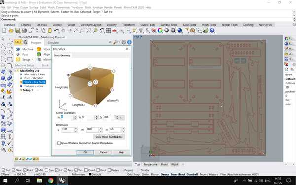
Next, I shifted to the Windows partition of my computer and installed RhinoCAM. I opened the RhinoCAM machining browser plug-in in Rhino6. First I set it to MILL. In the program tab, I set up the material stock - 1220x1220x15.5 mm, the machine details - 3 axis , post - shopbot.
I set the origin at the left bottom corner and the Z at the top of the material stock.
Next I set the tool - Flatmill 6mm, refering to the class notes and some previous documentations:
Saved the tool as Flatmill 6mm
Holder dia = 50
Holder length = 45
Shank dia = 6mm
Tool dia = 6mm
Shoulder length = 30mm
* Flute length = 30mm
Feed and speeds:
Speeds: 12000 rpm
Plunge: 2000 rpm
Approach: 2000 rpm
Engage: 2000 rpm
Cut: 2000 rpm
Retract: 2000 rpm
* Departure: 2000 rpm
Next, in 2-axis functions there is a list of actions you can perform. For my design I needed engraving, profiling and pocketing.
Engraving
I set 5 points in the rhino file to engrave markings for screws to be drilled with a hand drill in the correct places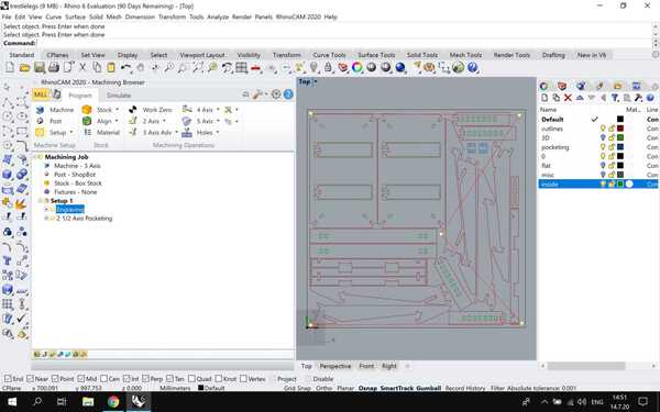
Pocketing
The insides of some parts that needed to be cleared were cut first. 2 parts needed pocketing at different heights, So after making adjustments in 2 different layers I changed the cut depth for both. 15mm for all parts except 2 where it was 10mm.
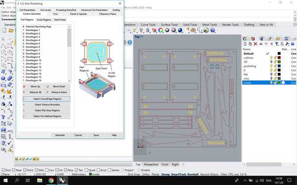
Settings:
Cut pattern: Offset
Cut direction: Conventional (Up cut) - standard for plywood
Start point: inside
Rough depth: 12
* Finish depth: 3
Profiling
To cut the outside profiles of the parts, I set the profiling for 2.5 axis. I also made another profiling - inside for 2 curves that needed to be cut on the inside.
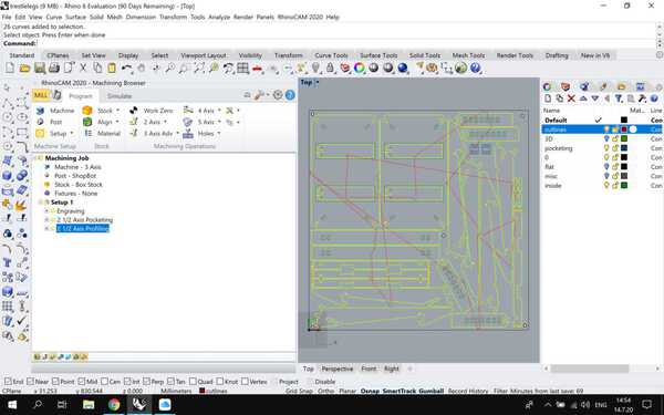
Settings same as pocketing, set toolpath OUTSIDE the curves
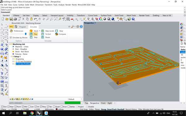
Simulation
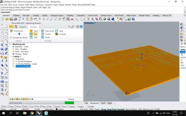
Then I ran a simulation and found some errors in the settings.
1. The cutting height did not match the level of the stock. It was cutting in the air. I adjusted this by going back to the material panel and changing the stock thickness to 15mm. (It was 300 by mistake)
2. The tool path just ran once over all profiles and went in 15mm in one pass. I changed this by making the cut depth 15mm in roughing and finishing at 12mm and 3mm respectively.
3. Some parts were creating double paths - so I deselected them from one layer and generated toolpaths again.
After running another simulation, it seemed fine.
I didn’t get a chance to actually cut using the RhinoCAM gcode. You can find the design files at the end of this page.
Vcarve Pro
The standard workflow at FabLab SP was to import the dxf in Vcarve Pro and generate the gcode.
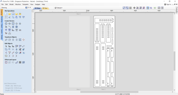
I used the full version of Vcarve Pro 11 at the lab.
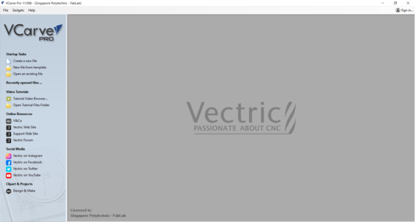
First step is to start a new file specifying the size. In my case Width 2440mm, Length 1220mm and Material thickness 17mm.
Using the rulers on the side, optionally set margin guides. I do this with an offset of 20mm inside the edge of the material. This 20mm space is for screwing the material on to the base before cutting.
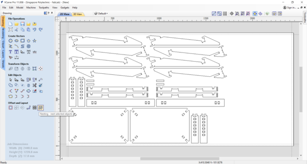
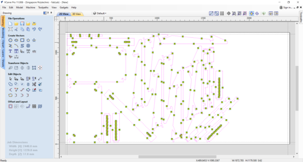
Next, import the dxf.
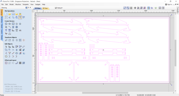
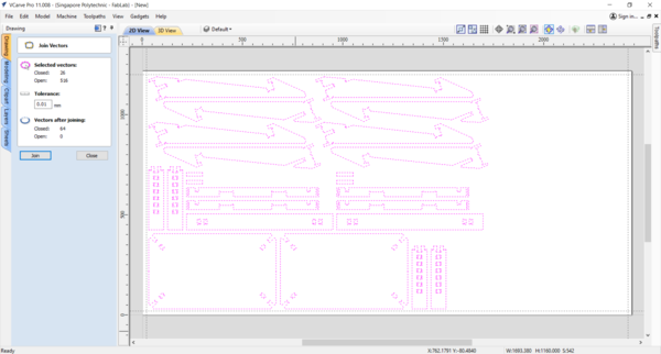
Make sure all the curve are closed. If not, you can join them (J) from the menu bar.
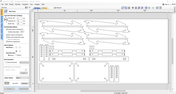
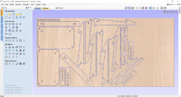
Vcarve actualy has in-built nesting capabilities, this is very convenient.
To save more space, I try nesting with 45deg and enable part mirroring. This changes the grain of material for the same parts, but since I’m experimenting and learning, I go ahead with this.
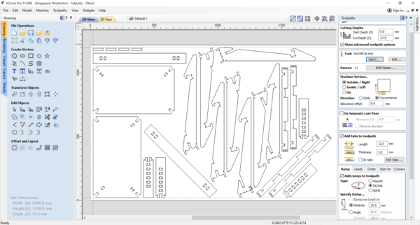
Next, recheck and set up the material dimensions. Also, select material top surface as origin. And left bottom corner as XY datum. In the toolpath tab on the right >>
Tool path Settings:
Cutting Start Depth: 0 mm
Cut Depth: 17.5mm (I keep this more then the material thickness, to foolproof cutting through in case of uneven bed level or material inconsistency)
Tool: 6mm endmill
Machine vectors: On the OUTSIDE (Vcarve automatically cuts inside curves on the inside)
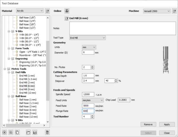
I’m using a 6mm flat compression endmill made of T carbide. So from the database, I select the correct bit and change the settings a little.
Tool diameter = 6 mm
No of flutes = 2
Spindle Speed = 12000 pm
Feed rate = 5000 mm/min
Plunge rate = 600 mm/min
Pass depth = 6 mm (=tool diameter, good practice)
Next, adding tabs so that the cut parts do not fly out. I set the tab size to Length 12mm and depth 3mm to make it easy to cut later on. Again Vcarve has a convenient automatic tab generator. This can be customised using no of tabs, distance between tabs or even done manually by clicking on the lines. I found setting tabs by distance 200mm gave optimal results, with a slight extra effort to move around some tabs.
After manually checking for all tabs, set machine vectors to outside, so that the kerf is outside the actual curve.
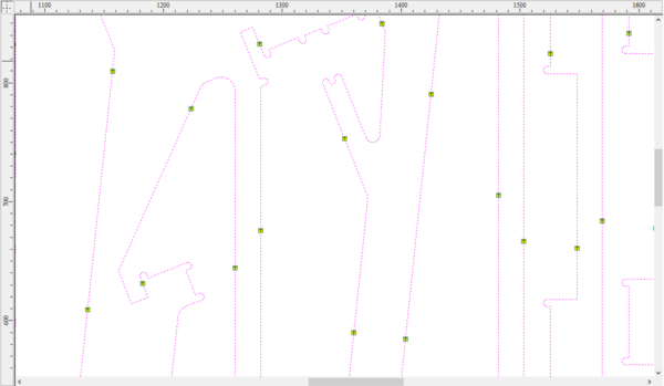
Single click to add a tab, double click to remove, and drag to move an existing one.
The software automatically places the inside nested curve toolpath inside without making a different layer for it.
Add a ramp.
I added a 15mm ramp so that the tool doesn’t plunge directly into the material.
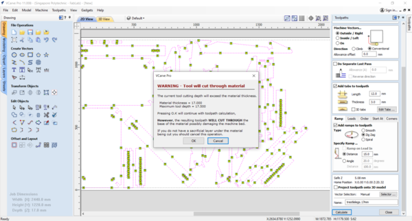
On ‘calculate’ I got a warning popup saying the cutting depth exceeds the material thickness. I bypass this warning as the deeper cutting dimensions allows to cut the material without burr and accomodate the difference in material flatness and thickness. Also if there is any variation in the bed levelling. It will basically cut through 0.5mm through the waste sheet.
The file is almost ready. Last step is to simulate the cutting and check if it works properly. This is important before actually cutting. You can control the speed of the simulation and check the toolpaths in detail.
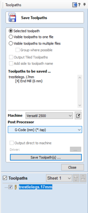
Save a .tap format (gcode) file in mm and send it to the computer of the CNC machine. There are multiple options of saving different profiles in one or multiple files.
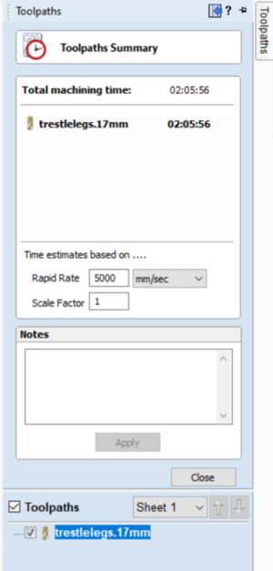
You can click the clock symbol on the tool path taskbar and by setting scale and feed, simulate the time it will take for cutting that particular profile. This is not super accurate, but helps in approximating the actual time exclusing the material setup and cleaning later on. I later found this was way off.
5. Test settings
I did the group assignment of this week by myself at the lab.
Using a 17mm ply, I made the pockets 10mm deep and then made a slotted joint.
The wood I used for this was very soft, so it cut very clean in the milling machine, but cleaning it with a file was very difficult.
On fixing the pieces togther, they weren’t as clean as I imagined, and not as accurate.
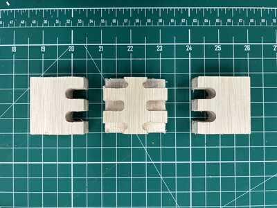
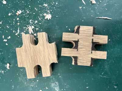
To test the kerf of the machine, I made a simple pocket joint in Rhino.
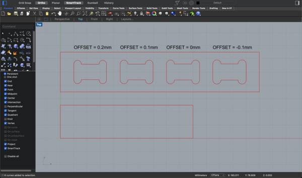
I made varying offsets of the pocket to figure out the best fit.
You can find the design file here
Using the same settings and workflow as mentioned above, I used Vcarve Pro to make the gcode.
I used a 12mm thick ply to cut these pieces.
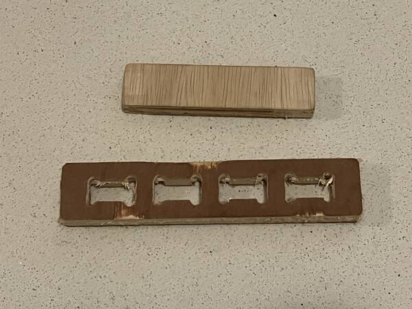
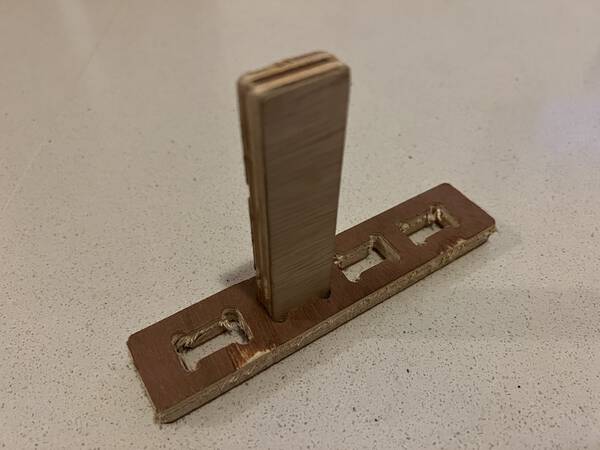
On lightly filing the edges, I tried out all the 4 options. the Frist 2 were quite tight, the third was just right. Meaning, the design doesn’t need any offset, because the minimum amount of filing and cleaning itself makes it good enough to make an accurately fitting joint like so:
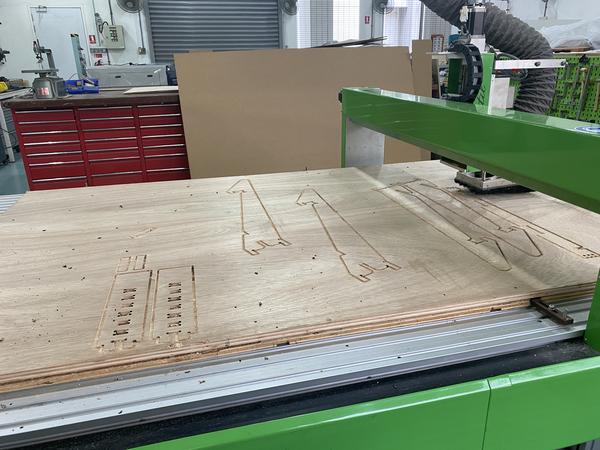
6. Machining
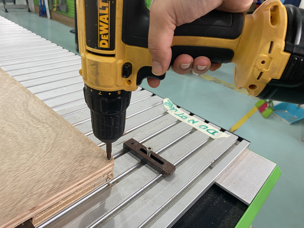
First mount the sheet on to the bed of the machine. Align properly with the waste board.
Using a power drill, drill in screws to fix the sheet. Do this within 20mm from the edges of the sheet, so the tool doesn’t interfere with the screws. Also use countersunk screws so that the cap height remains flush with the material surface.
Set X, Y origin at the left bottom of the sheet.
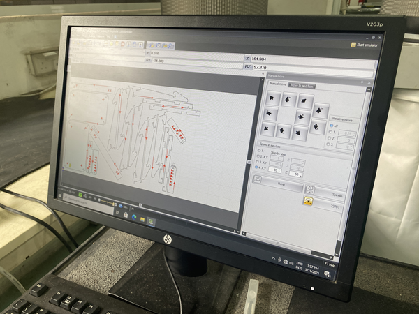
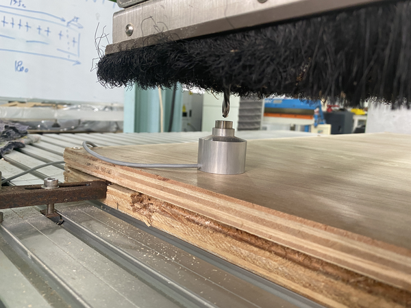
Open NC-pro on the computer that is connected to the machine and check origin. I do not change X and Y as they are set already as default. To set Z origin, I use a tool sensor. By temp moving XY to 150,75, put the probe below the tool and set ‘tool Measure’. This basically sets the Z at the top of the material.
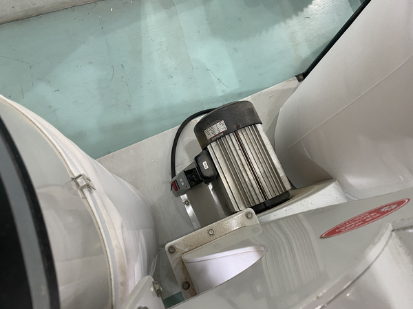
Next, start the dust collector.
On the remote, press ‘start’ and ‘OK’.
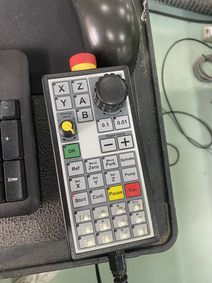
The spindle will start. The machine in the lab has a spindle regulator connected directly to it. So it doesn’t use the setting from the gcode created in Vcarve.
Cutting should now start. My file took approximately 2 hours to finish. It is very shrill and loud, so it is important to wear ear protection.
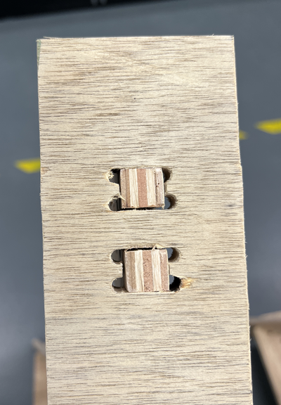
The plunging created some burn marks in the holes.
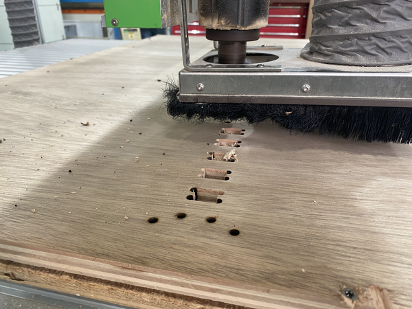
I noticed that the toolpath doesn’t optimise paths by distance. Unlike in a lasercutter it cuts across the sheet in random(?) order.
After cutting is done, I unscrew the board from the base.
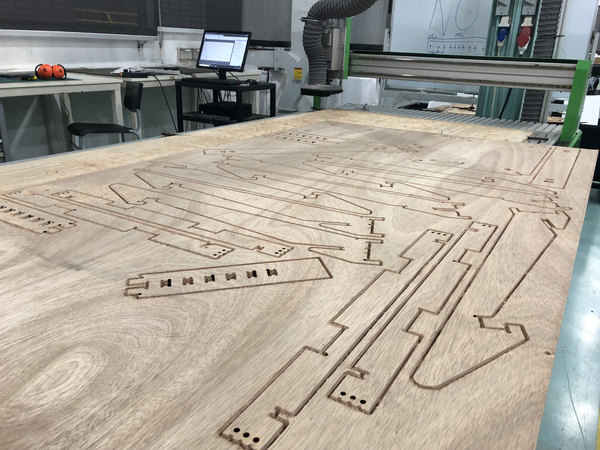
I vacuum all the remaining dust that the dust collector missed and on inspecting the cuts, realise that the material didn’t cut through.
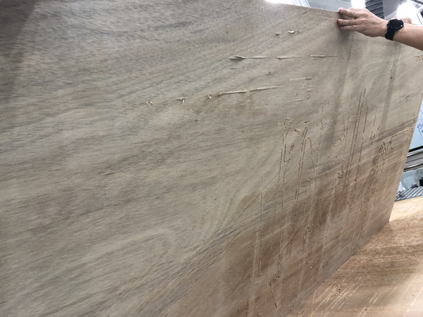
With Steven’s help, I chiseled off all the tags from the pieces and found some pieces had to be cut again because they hadn’t cut through with enough detail.
7. Assembly
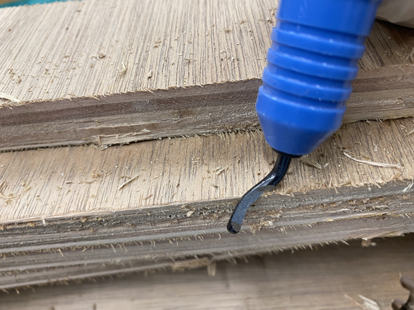
The machined parts have very rough edges, so I first used a burring tool to cut off chips.
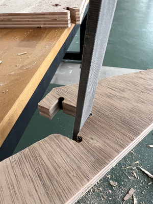
I use a file to clean joint details.
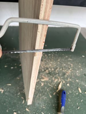
And a hacksaw to cut off remains of tabs.
There were still chipped off corners, so I used an orbital sander with a grit 1000 to sand off all surfaces.
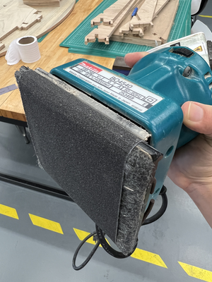
Difference between sanded and unsanded parts:

This took up a lot more time than I anticipated, but the difference was apparent in the finished product.
So this is important to do before assembly. I wonder if in the future I can make setting to omit sanding parts altogether.
Sanded and unsanded details:
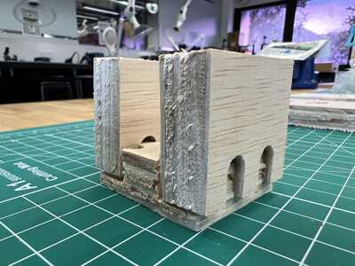
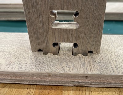
I started assembling all parts together. Here are some pictures of details.
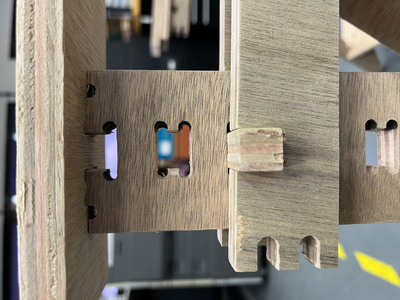
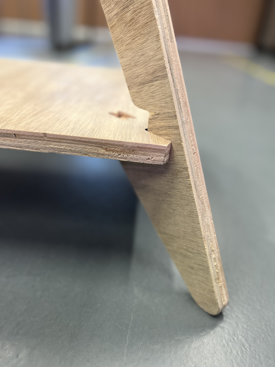
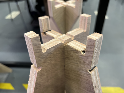


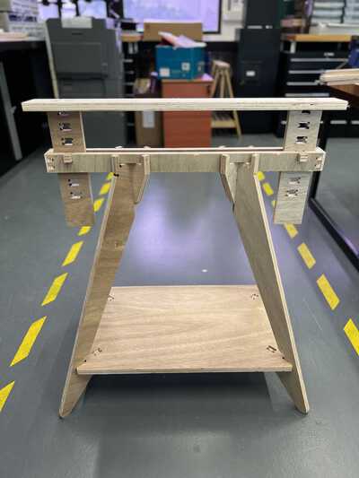
Here’s one finished part:
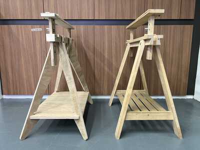
Here it is besides an actual IKEA Finnvard:
Here are two of them:
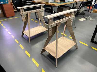
And now by changing the height, its ready to use as a desk:
I has to recut these pieces as they were designed for 15mm thickness and not 17mm:
8. References
IKEA Finnvard trestle
This CNC wood joinery post
50 Digital Joints
Digital Fabrication for Designers blog
9. Design Files
For 15mm version using RhinoCAM:
Rhino 3D
DXF
Parts stl
Full stl
For 17mm version using Vcarve Pro:
Rhino 3D
DXF
Parts stl
Vcarve
gcode mm (.tap)