7. Electronics design
Group assigment: test the equipment
The link: Roger
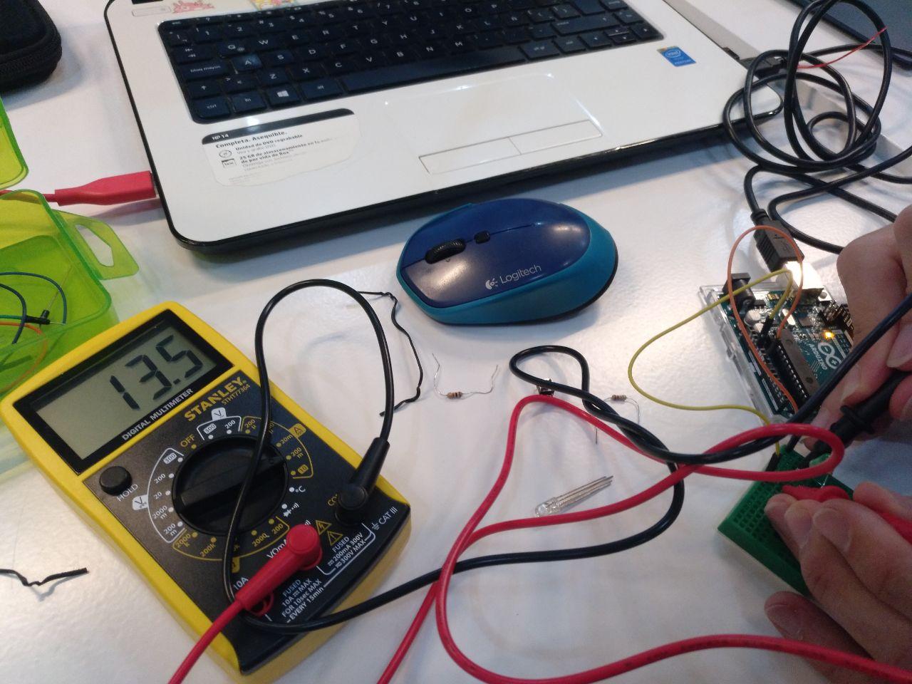
For testing the equipment we had the basic electronics class where we used some beds for testing the current, voltage and resistance of resistors and boards. I teamed with Roger for this and we played with an arduino kit.
I’ve used already a multimeter (or tester), but it was a long time ago when I was more used to their use, so a refresh and a little sandbox to play with was very handy.
In this class we used an arduino as a battery and used capacitors and different pieces to know how they work.
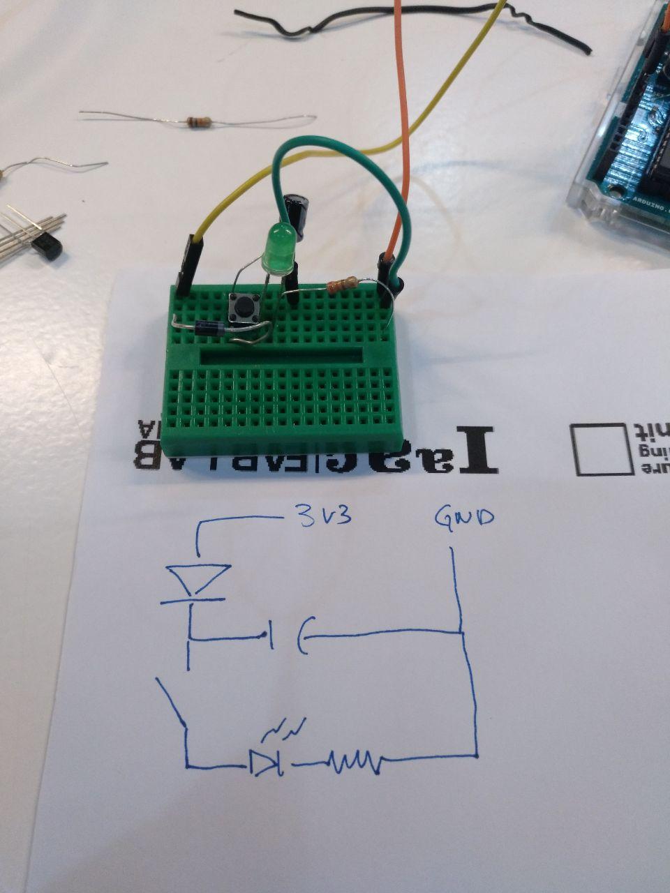
but the breadboards are difficult to understand if you don’t have a drawing
And when we used the multimeter we could see the difference between the positive and the negative current. Useful to know wher do you have to put your diodes or leds!
current in a way
current in the other way
Individual assignment
First I thought of doing a full ESP32 board that I could reuse. But personal schedule problems prevent me from this and also that I didn’t get where to connect everything or if we starts from Barduino what can I add or substract.
So finally I decided to do an ATtiny44 that seems more accesible.
I used Kicad because we had a Kicad class that helped with it.
Kicad worksflow
The kicad workflow is quite strict and you have to follow properly the steps. It reminded me when I first learnt AutoCAD when you have the drawing and you have “the model” and “the presentation” so you have several layers.
So the process it’s the following
1) You start with an idea of what do you want (by hand or you take frome somewhere). I think having a sketch is necessary so you have a map of what to do. In this case I have the echo board from Neil for the ATtiny44 echo board (1 side)

In this case there is something that I learnt after doing all of this but I should have done better.
Types of pins
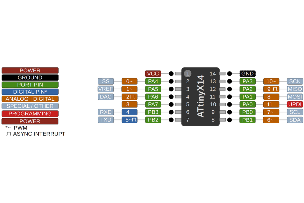
I think that it’s important to know at least the basic kinds of pins:
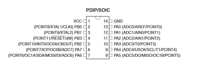 the pins from an ATTiny44 as they come in the datasheet
Some important ones:
GND: this is always ground. 3V3/VCC/5V: this is always 3.3V or 5V. XTAL and XTAL2: This goes to the clock RESET: This is the reset buton.
Then, depending on the microcontroller you can check if the other pins are for, if they have analog to digital conversion or if they have internal pull-up or pull downs resistors.
They usually go with a PB[number] or PA[number] based on that you can check for other options.
In my case when I did this first design I wasn’t even sure about what’s a pull up resistor. (a pull-up resistor is a mechanism that ables to detect properly if something is connected or not)
Now you’re ready to open Kicad
 now with windows 2000 like gui
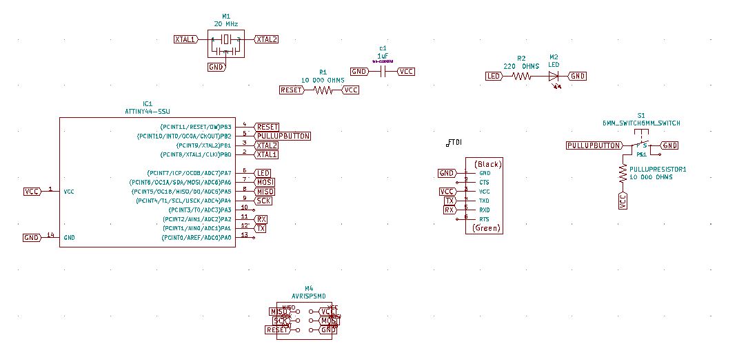
2) Then you make the schematic with the Eeschema. This is going to be very abstract. Here you have to set the components and establish what goes with what. In this phase you don’t see it where it’s going to be yet. Only where are the connections.
Here is the final result
An important idea where working here is to separate the components into functions. In this case, the clock (that we already have in the echo board), the pinsets (separate), the led and the button.
note
When you do this you have to set properly the libraries of the components you’re going to use. You need 2 things. The component itself (so you know how many pins does it have and the representation of them) and the footprint. The footprint it’s how phisically is set in the board. And both parts have to be linked to work. For the fabacademy components we have some specific libraries of the components we have so we don’t have to spend time finding them.
3) Once you have the schema, you can get a netmap. That is a file where there is the information of the components and the connections of all of them.
4) You go to the PCB Layout Editor.
In the PCB editor you have to load the netmap, check if you have all the footprints set and then you start untangling the mess and connecting it. In this case since we have the echo board as a reference we can go a bit faster because we know where does that go.
This is the result:
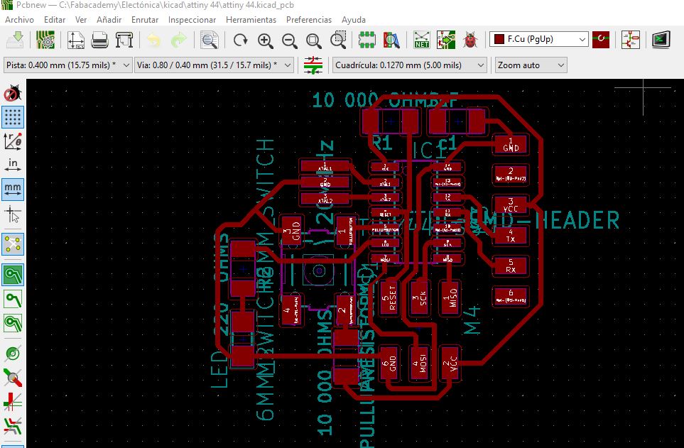 It seems more 90 future stuff than it really is
It’s important to set properly the chanels and measure the space of the trace and between traces (because that’s where the mill is going to pass!)
When you’re done you can make the svg files. That’s going to be the outline and the traces files to send to the mods.
5) (optional) double Check the svg files with illustrator.
In my case the exterior line I made it with illustrator because it’s easier for me to use it rather than the Kicad.
6) Go to mods and double and triple check the result
(measure twice, cut once)
To check it I revised if the trace file that you can preview didn’t miss any spot.
If everything is ok you can mill the board! If not you can go back in the different steps.
Things I learn designing it
Important thing to know is that when adding something to a microcontroller you need to attach it to one of the free pins (you need to see which are those in the datasheet or be told) and the other point will be ground.
In my first test attempt I added the switch and the led (with the resistor) in the same pin but when I revised the file this was not an optimal disposition. The reason is that with 2 pins we can test and program the button and the led to do different things and have different routines that we can’t reach easily without them. For example that if you press the button the led starts to blink. If you want to do that without the microcontroller you would need a more complex circuit.
So after the second attempt I went to the CNC milling machine. For some reason (I think that the bed is too flexible) when I cut the traces of my board they got polished instead of cut.
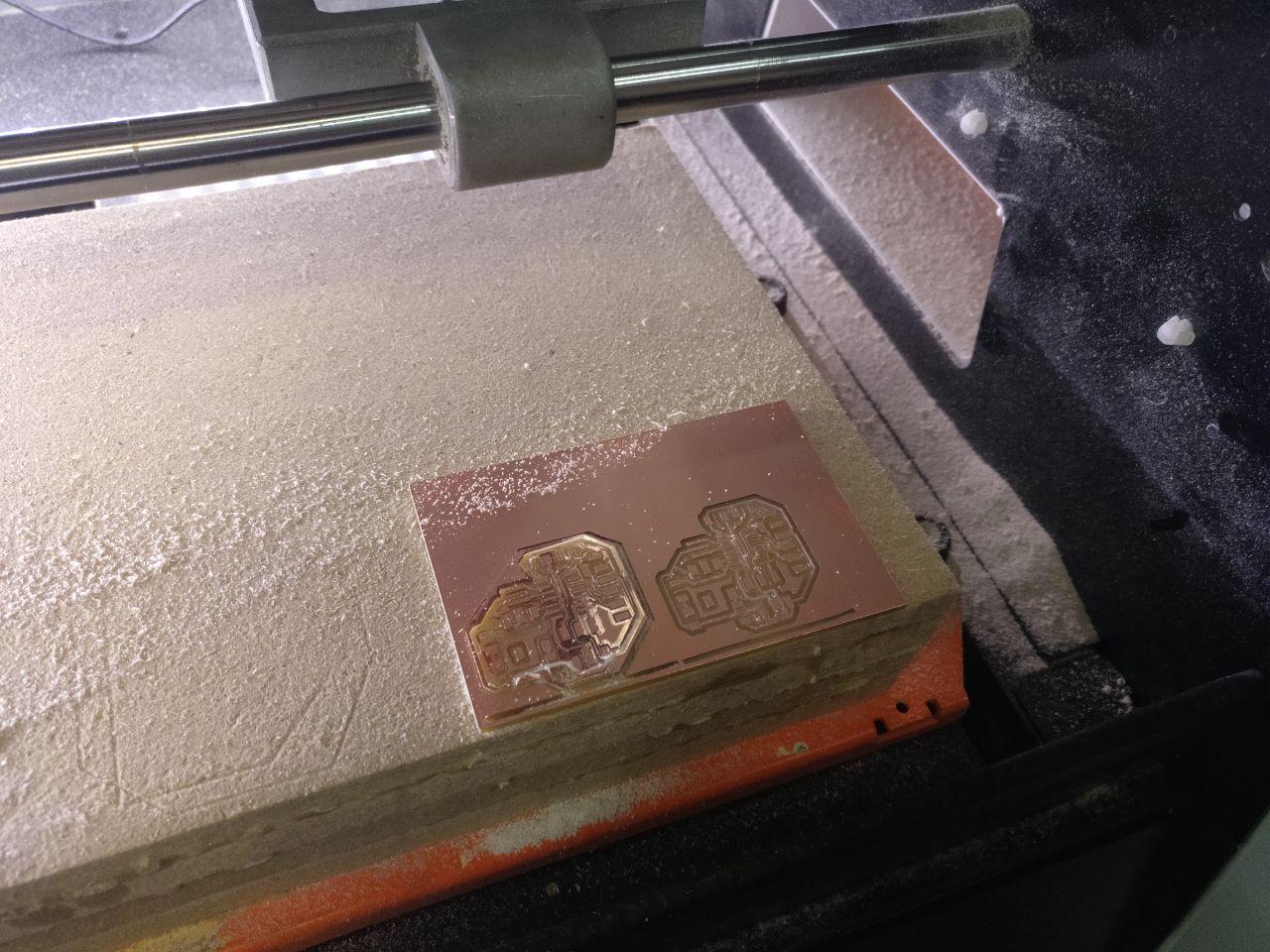
polished results from the CNC
So I had to retry a couple of times. In the third one the outmill went almost well but it still had polished uncut parts (in dark in the image) that I detected using the multimeter.
seems well but no
When I tried to cut with a blade those parts a teared apart one of the lines so it was futile and I had to make it a fourth time.
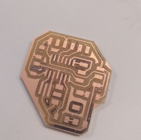
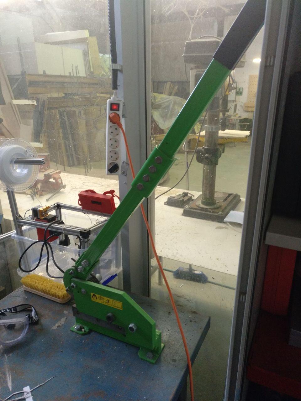
The last cut went well but I couldn’t make the outline because we needed the machines to do barduino for all of us to the next weeks (due to Covid19) so I cut the outline manually with a guillotine.
Powerful with a bit of sanding
Soldier process
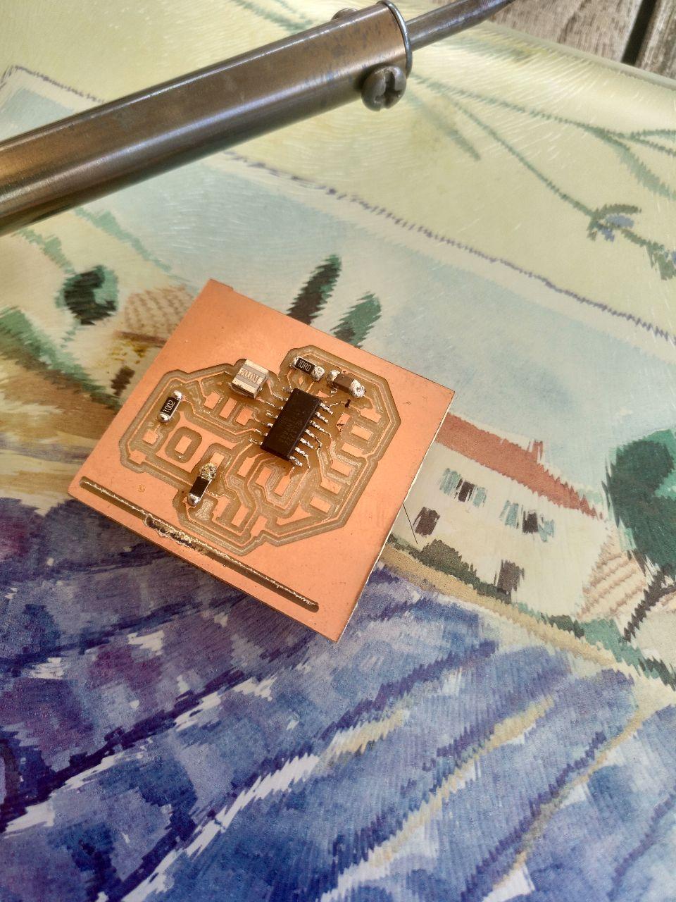
That last day in the lab, I spend the time welding the Barduino that was printed so we can do the rest of the assigments and I can only managed to have the ATtiny44 soldiered to the board.
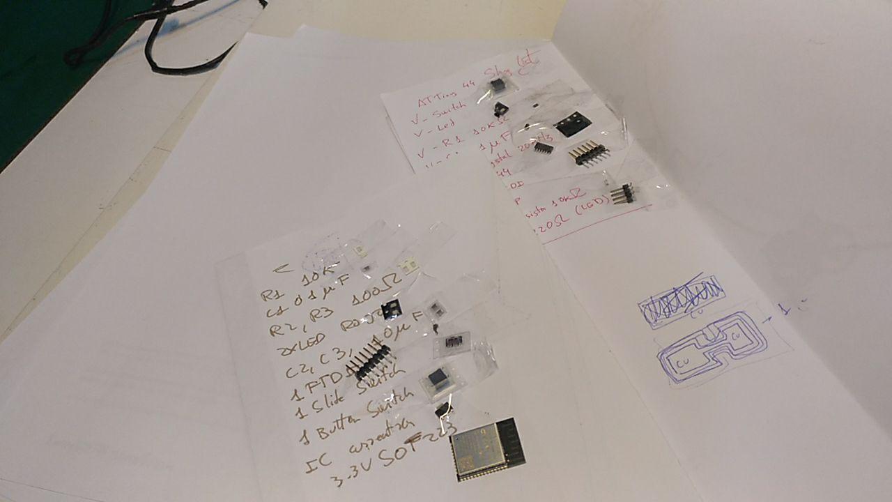
The two shopping lists
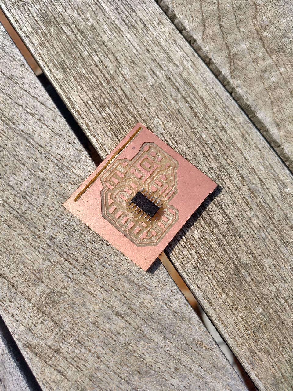
Result with the mircrocontroller but not the other components
Next day I went to a bazar and I bought a soldering iron and some soldering cable. I thought it was enough but days later when I had the time to soldier the board, I found that the cable was 2.0 mm and in the interior had something so it didn’t soldier properly. So that has to be stopped until I go back to the fablab or another hardware store.
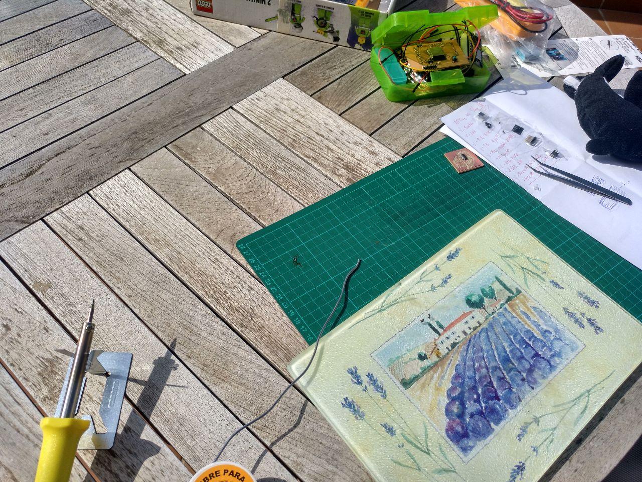
I was ready to soldier stuff!
But the cable betrayed me. Top 10 anime betrayals
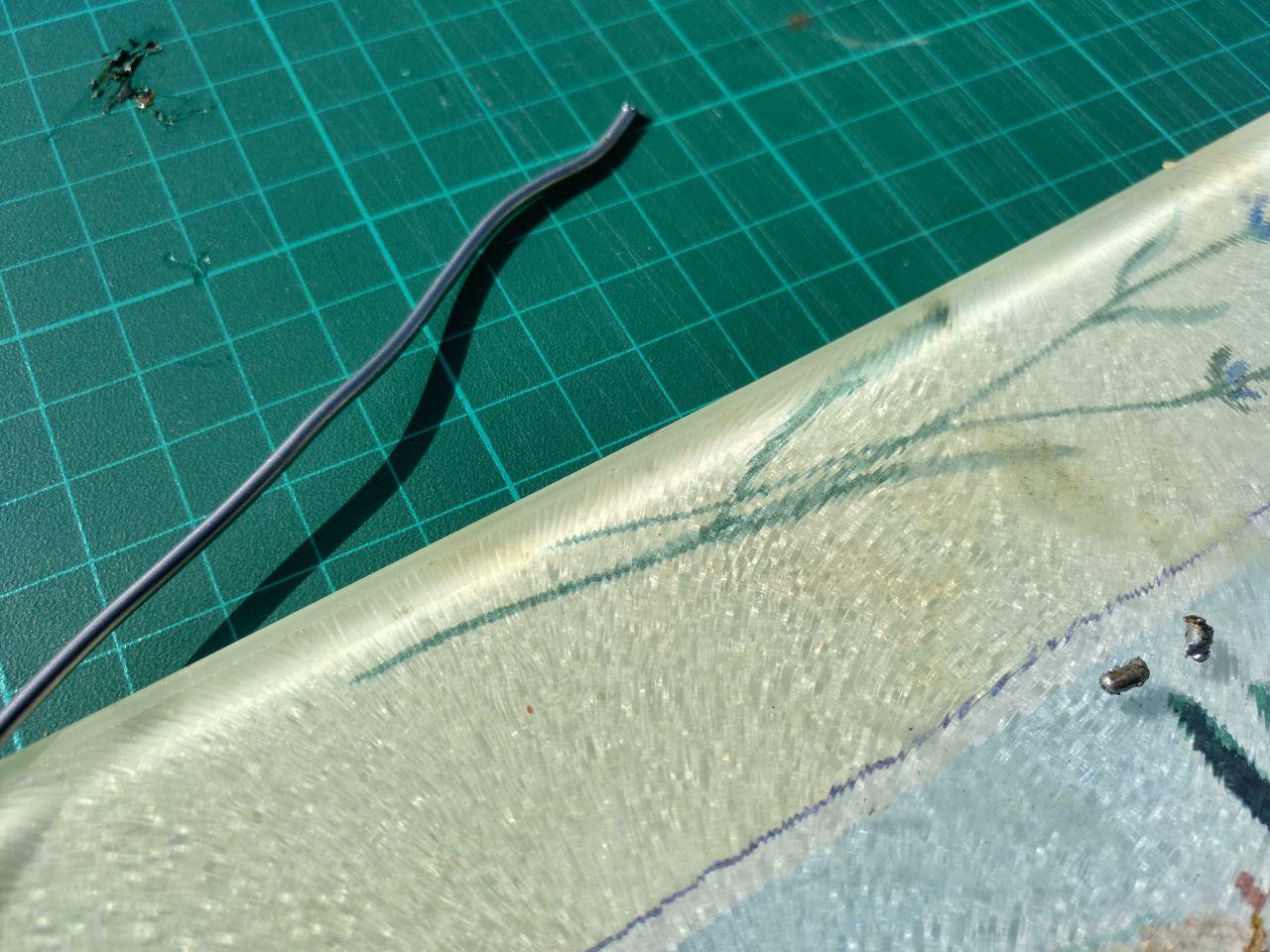
Some ~~days~~ weeks later I could get some wire from the lab.
This is waaaay different.
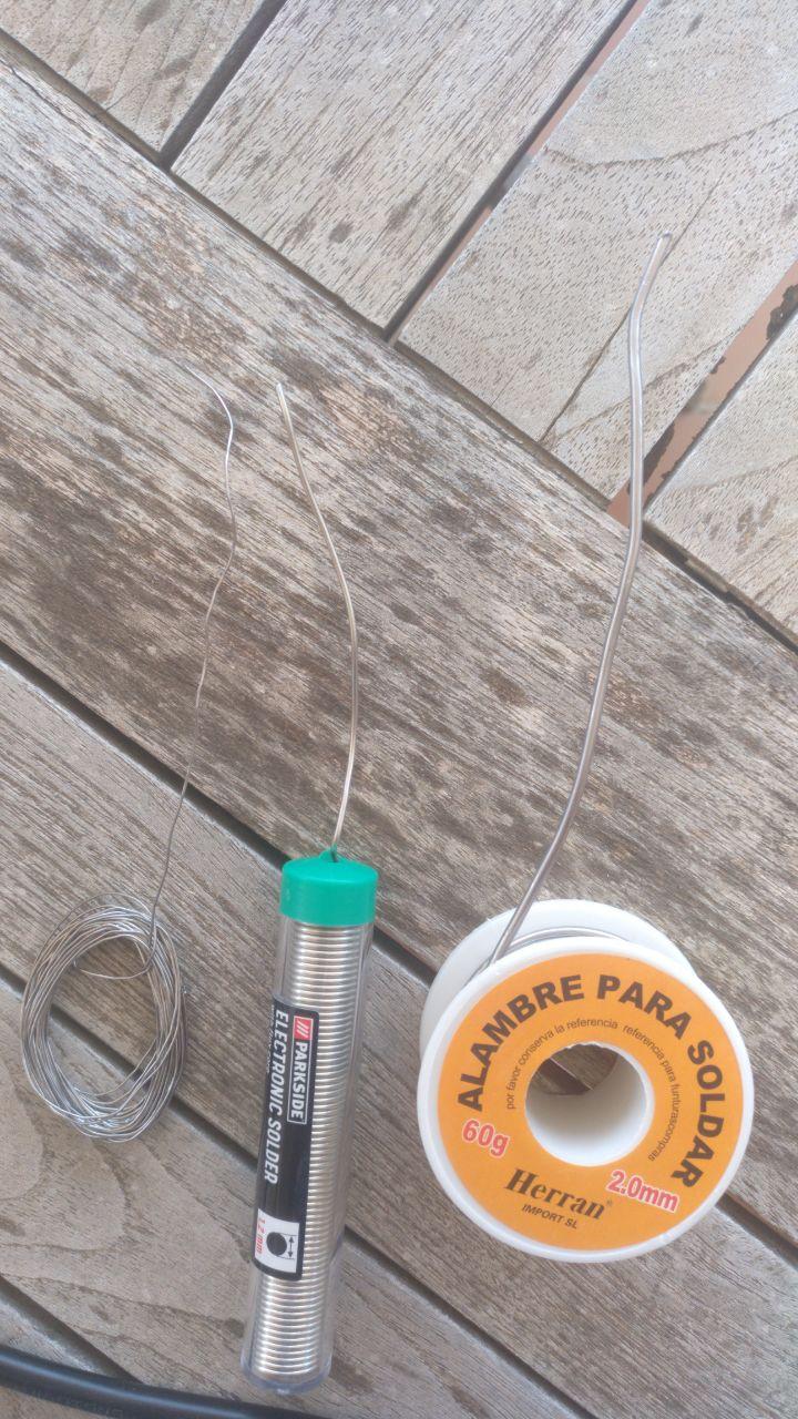
in the middle there is some wire I could get
Now I can progress in the soldiering with the shopping list. Always checking with the multimeter everything is ok.
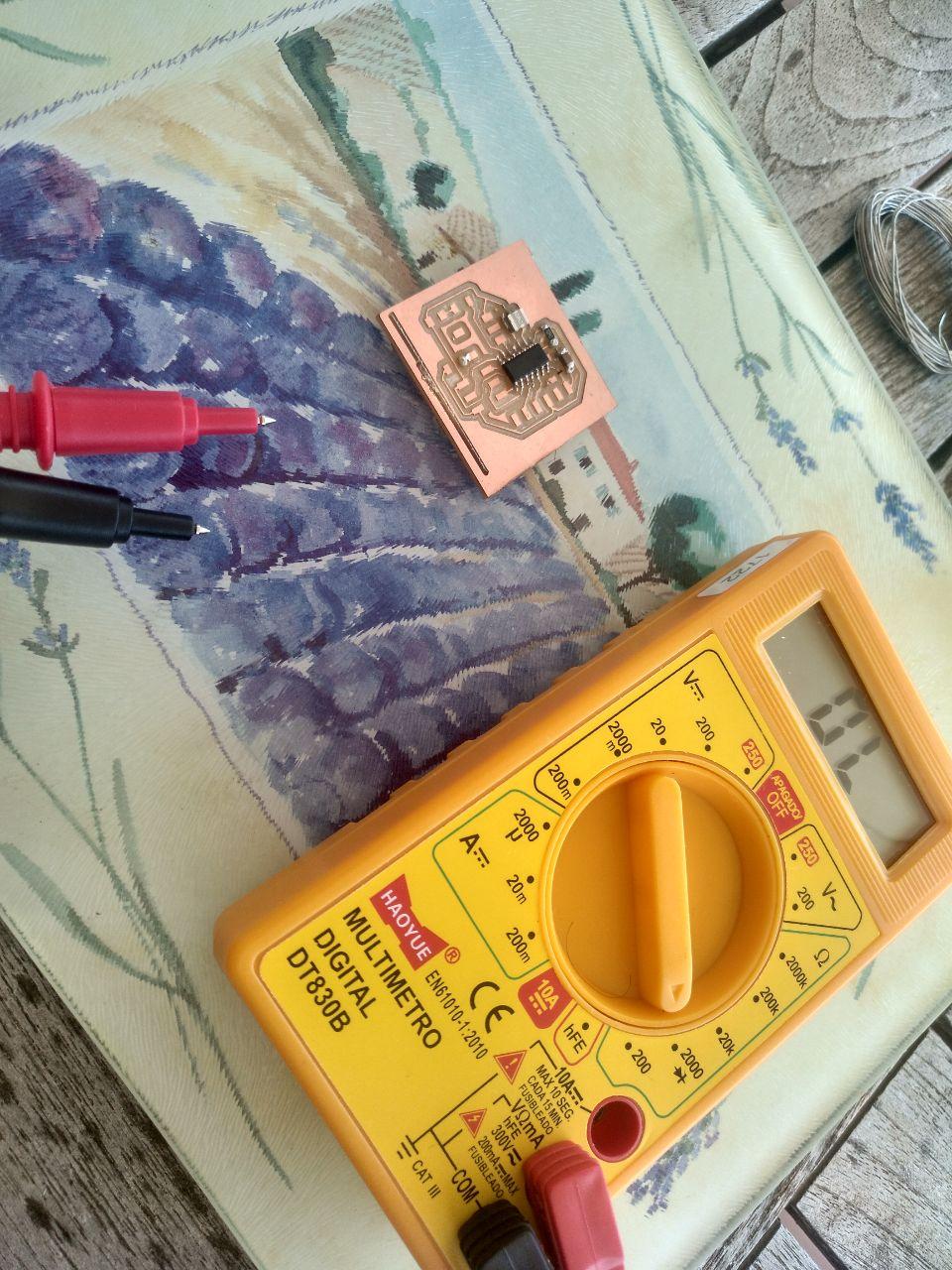
the multimeter is now off but I used it!
And finally:
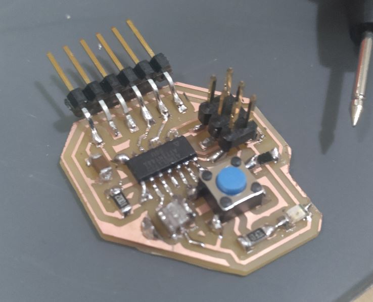
Hero shot
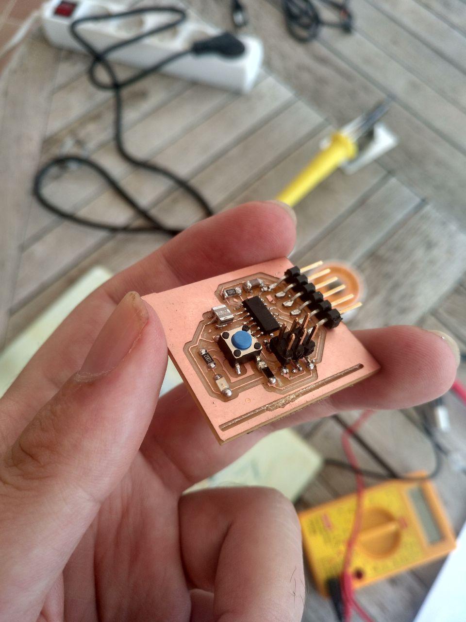
I am proud of my little child
Once the soldering is Off
Ok, now I have the board I designed from a variation of Neil’s. Now I have to have a ISP programmer… that I don’t have.
Using an arduino as a ISP programmer
I had to ask for an Arduino to Roger that lives in the same city I do (Because in the time we were separated from Barcelona in the lockdown).
I’m trying first to reprogram the malfunctioned Arduino I have. So I’m following this guide
I had some errors, that may be have to do with the wiring. Following Oscar advice I test with the multimeter the arduino to check that the continuities are ok and the position of the ISP is correct.
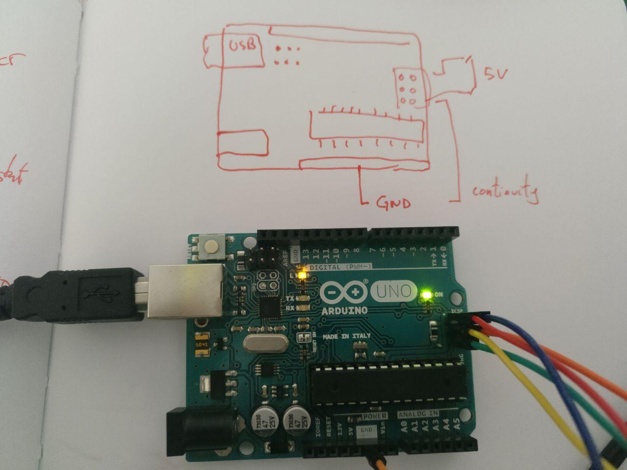
https://fabacademy.org/2019/docs/FabAcademy-Tutorials/week08_embedded_programming/attiny_arduino.html
The idea it’s first to test it with the program of echo that Neil made
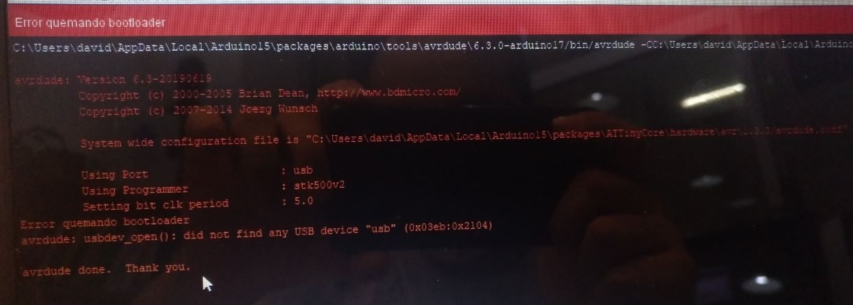
Um, I try to burn the bootloader (As the tutorial says) and I have (Again) something that seems a wiring error
Arduino:1.8.12 (Windows 10), Tarjeta:"ATtiny24/44/84, Enabled, ATtiny84, 8 MHz (internal), EEPROM retained, B.O.D. Disabled, Clockwise (like damellis core), Enabled, Port A (CW:0~7,CCW:3~10)"

C:\Users\david\AppData\Local\Arduino15\packages\arduino\tools\avrdude\6.3.0-arduino17/bin/avrdude -CC:\Users\david\AppData\Local\Arduino15\packages\ATTinyCore\hardware\avr\1.3.3/avrdude.conf -v -pattiny84 -cstk500v1 -PCOM8 -b19200 -e -Uefuse:w:0xFF:m -Uhfuse:w:0b11010111:m -Ulfuse:w:0xE2:m -Uflash:w:C:\Users\david\AppData\Local\Arduino15\packages\ATTinyCore\hardware\avr\1.3.3/bootloaders/empty/empty_all.hex:i

avrdude: Version 6.3-20190619
         Copyright (c) 2000-2005 Brian Dean, http://www.bdmicro.com/
         Copyright (c) 2007-2014 Joerg Wunsch

         System wide configuration file is "C:\Users\david\AppData\Local\Arduino15\packages\ATTinyCore\hardware\avr\1.3.3/avrdude.conf"

         Using Port                    : COM8
         Using Programmer              : stk500v1
         Overriding Baud Rate          : 19200
         Setting bit clk period        : 5.0
         AVR Part                      : ATtiny84
         Chip Erase delay              : 15000 us
         PAGEL                         : P00
         BS2                           : P00
         RESET disposition             : possible i/o
         RETRY pulse                   : SCK
         serial program mode           : yes
         parallel program mode         : yes
         Timeout                       : 200
         StabDelay                     : 100
         CmdexeDelay                   : 25
         SyncLoops                     : 32
         ByteDelay                     : 0
         PollIndex                     : 3
         PollValue                     : 0x53
         Memory Detail                 :

                                  Block Poll               Page                       Polled
           Memory Type Mode Delay Size  Indx Paged  Size   Size #Pages MinW  MaxW   ReadBack
           ----------- ---- ----- ----- ---- ------ ------ ---- ------ ----- ----- ---------
           eeprom        65     6     4    0 no        512    4      0  4000  4500 0xff 0xff
           flash         65     6    32    0 yes      8192   64    128  4500  4500 0xff 0xff
           signature      0     0     0    0 no          3    0      0     0     0 0x00 0x00
           lock           0     0     0    0 no          1    0      0  9000  9000 0x00 0x00
           lfuse          0     0     0    0 no          1    0      0  9000  9000 0x00 0x00
           hfuse          0     0     0    0 no          1    0      0  9000  9000 0x00 0x00
           efuse          0     0     0    0 no          1    0      0  9000  9000 0x00 0x00
           calibration    0     0     0    0 no          1    0      0     0     0 0x00 0x00

         Programmer Type : STK500
         Description     : Atmel STK500 Version 1.x firmware
         Hardware Version: 2
         Firmware Version: 1.18
         Topcard         : Unknown
         Vtarget         : 0.0 V
         Varef           : 0.0 V
         Oscillator      : Off
         SCK period      : 0.1 us

avrdude: AVR device initialized and ready to accept instructions

Reading | ################################################## | 100% 0.02s

avrdude: Device signature = 0x000000 (retrying)

Reading | ################################################## | 100% 0.02s

avrdude: Device signature = 0x000000 (retrying)

Error quemando bootloader
Reading | ################################################## | 100% 0.02s

avrdude: Device signature = 0x000000
avrdude: Yikes!  Invalid device signature.
         Double check connections and try again, or use -F to override
         this check.


avrdude done.  Thank you.
Going back to the soldering station
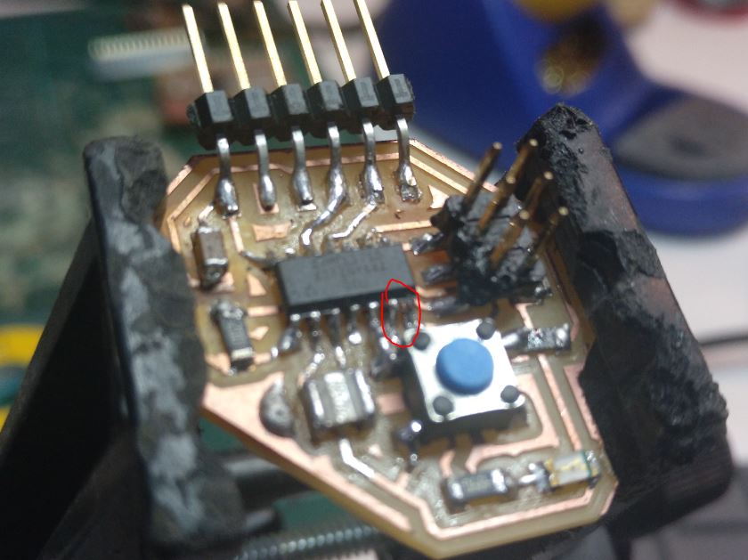
I talked with Edu and Oscar and they told me that I have probably to resoldier the board because with the photo they noticed (thanks to the HD) that there were lots of improvements to do.
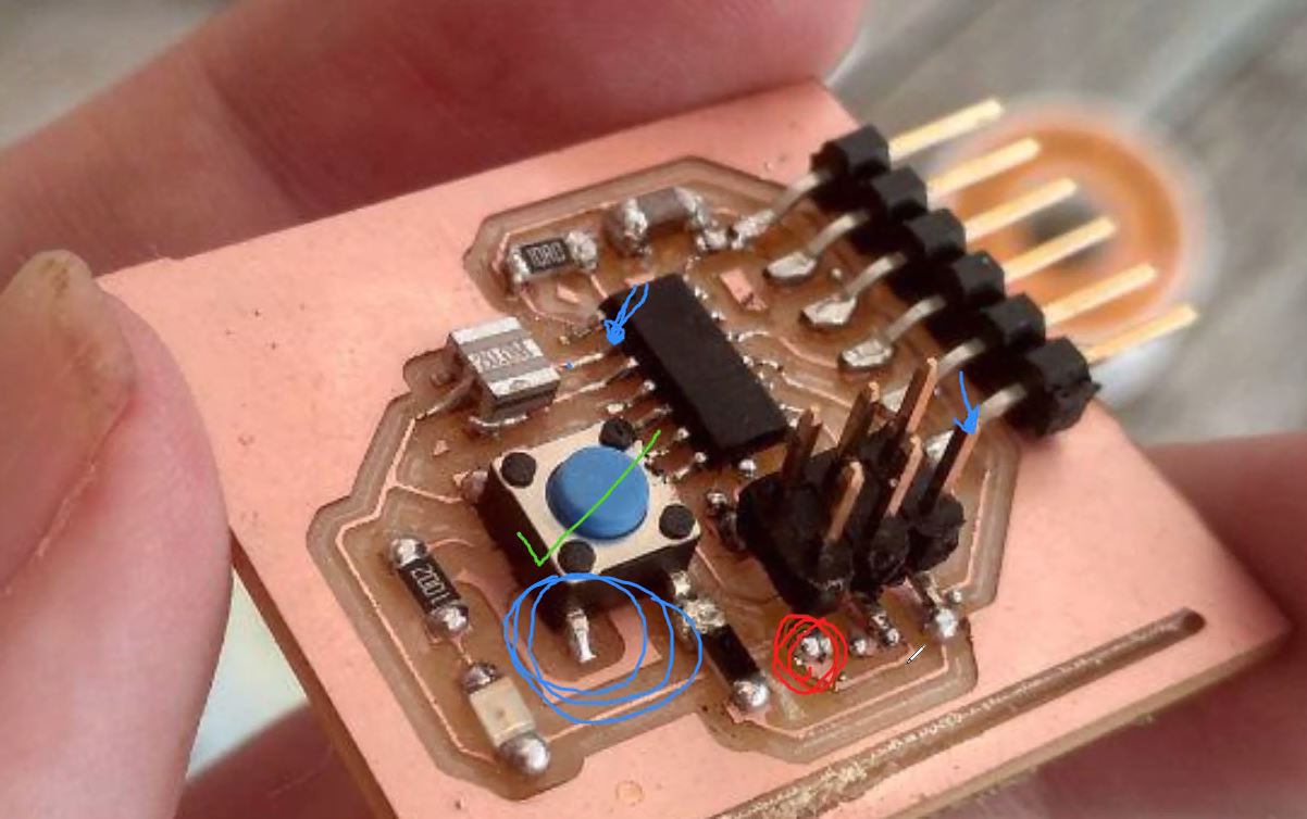
notes from them via Zoom
And this is the result (also I revisited the soldiering of a couple of barduinos but those seems to be fine)
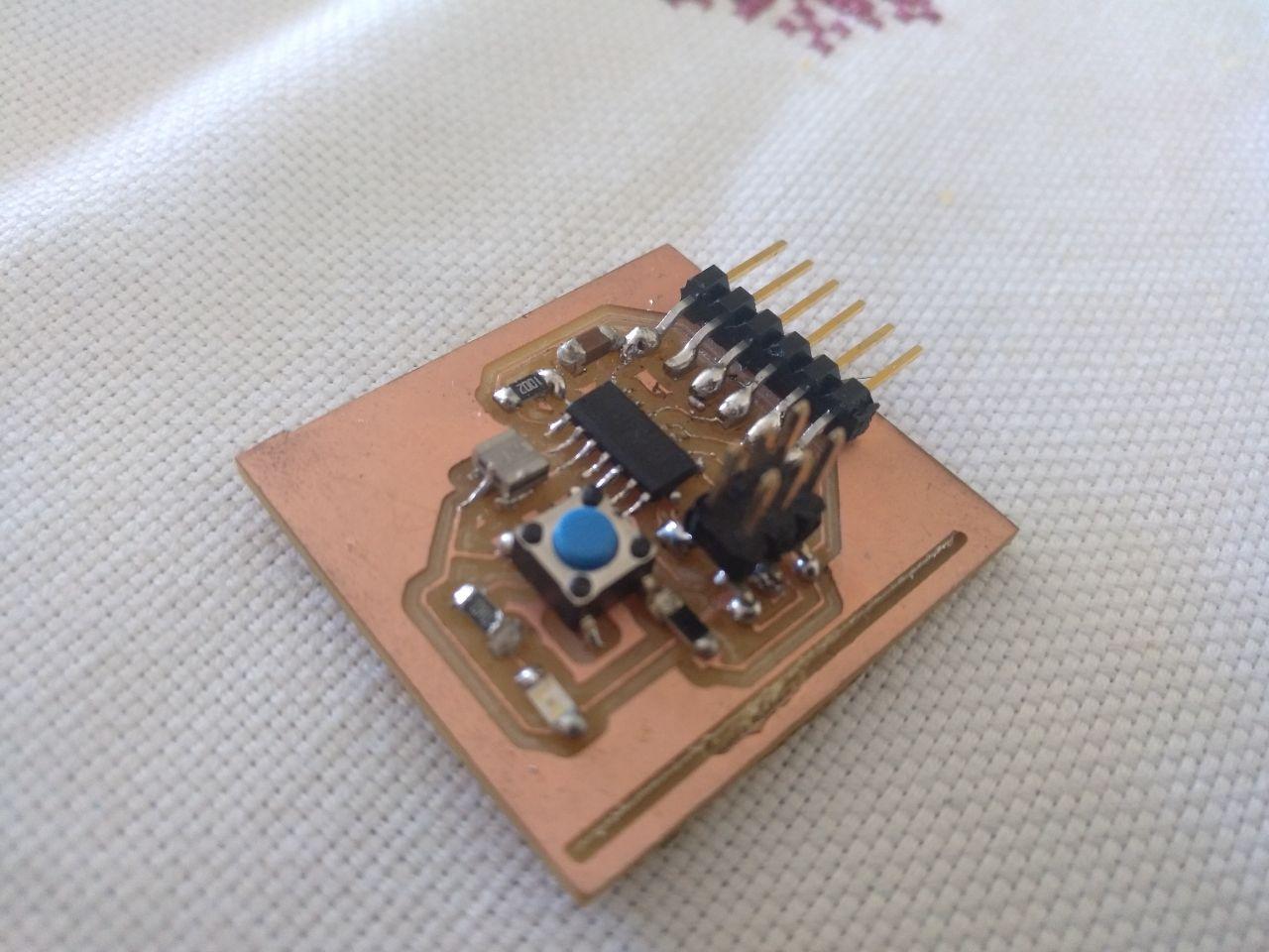
Shinier than you
I think that what I’ve learnt from this (from Edu) it’s to not only test the trace but from end to end of the line (for example, from the ISP tip to the microcontroller pin, on the top of it)
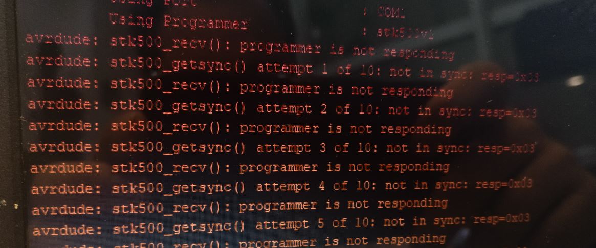
Now the problem I have when I wire it again it’s this one:
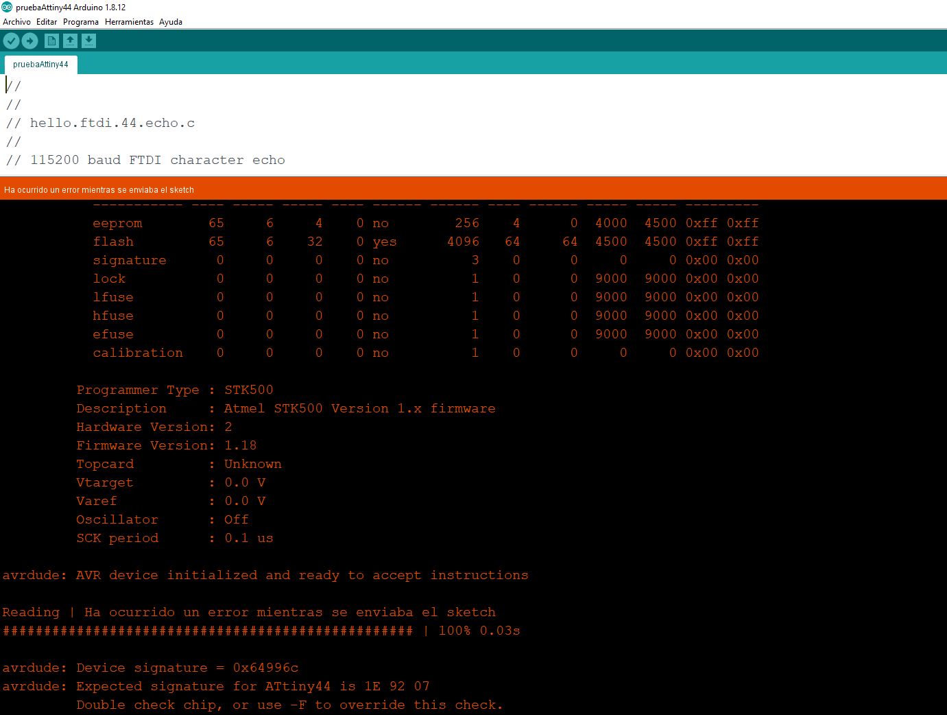
the error in the device signature
So now I’m not using an ATTiny 44? The arduino ide is looking for 1E 92 07 and the board is answering 0x 64996c
Digging up the error
I double checked that the microcontroller was the ATtiny44 (in this case ATTiny44a) but I tried once more and the bad device signature still happens but with another signature. Maybe it’s still a wiring problem?
Let’s check again.
Edu says that we need to change the microcontroller
Change the microcontroller
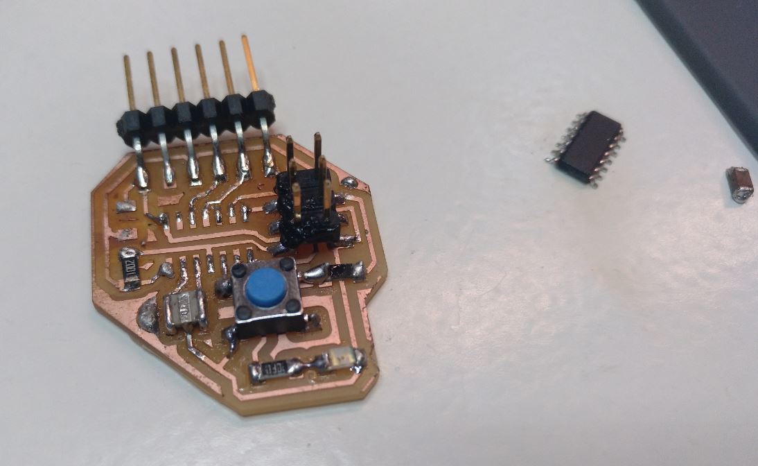
I unsoldier the microcontroller to change with another one. The bad news are that by doing so, I broke the traces and I can’t put them back together.
I think I need to mill another board. That would be the fifth?
Ugh.
disaster.jpg
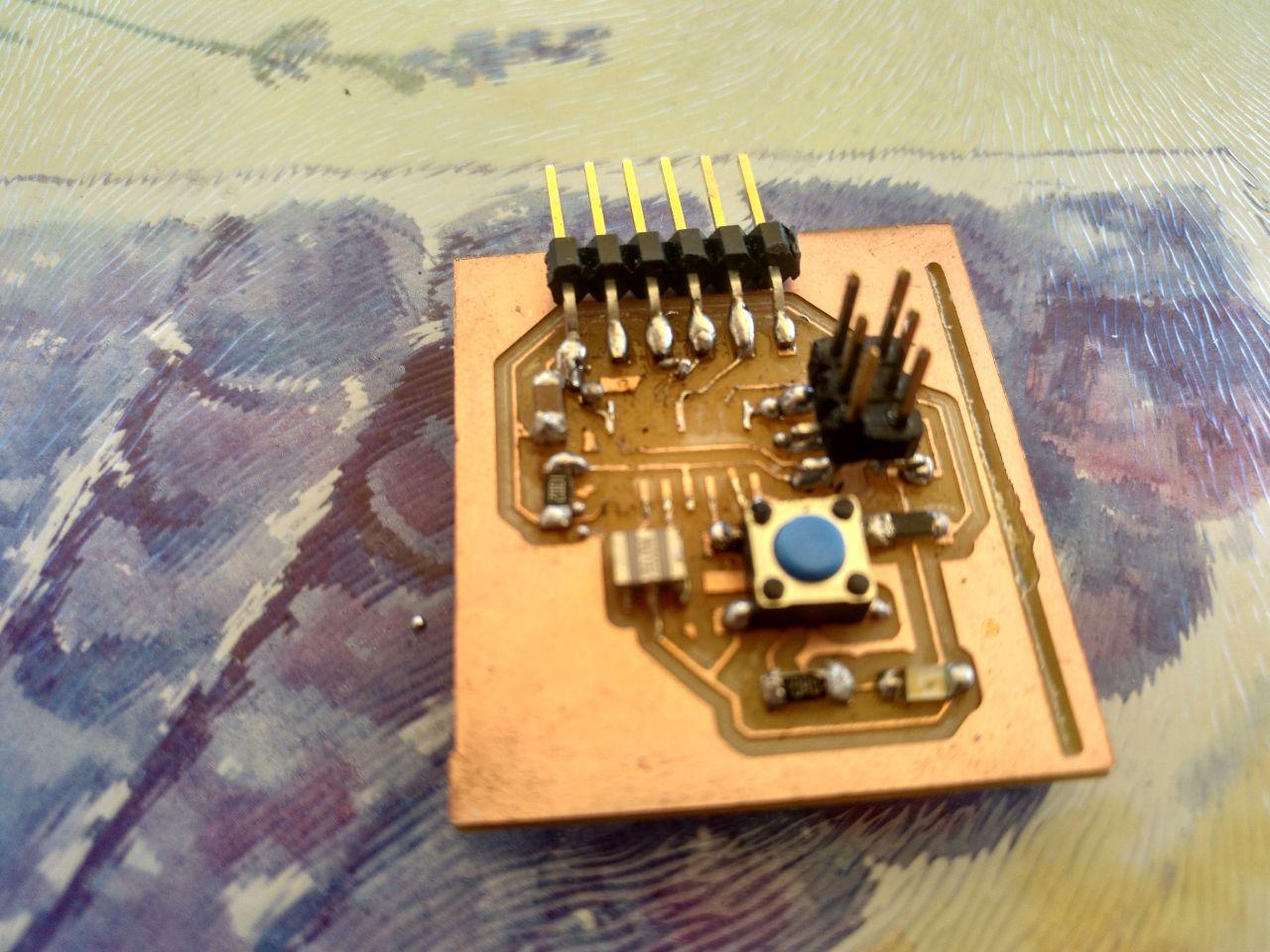
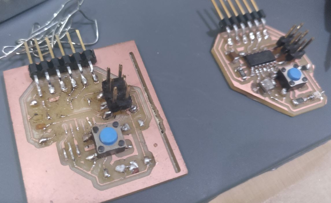
Once I change the microcontroller I realize that the traces are kind of broken. So I decided to mill another board.
New board
Now that I have access to the lab. I can mill another board easily. So I did. And I scraped what I could from the other board.
scavenge feels good
And it felt easier. Maybe because with the final project I’m having more experience with the soldier but I did it.
Result
Testing again
So I tried to program it. I tried two ways. With a programmer AVRMKII that is available at the lab using a computer from the Lab (with the help of Josep).
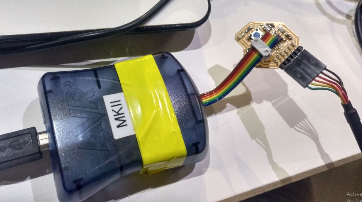
trying to plug it in
but it didn’t work.
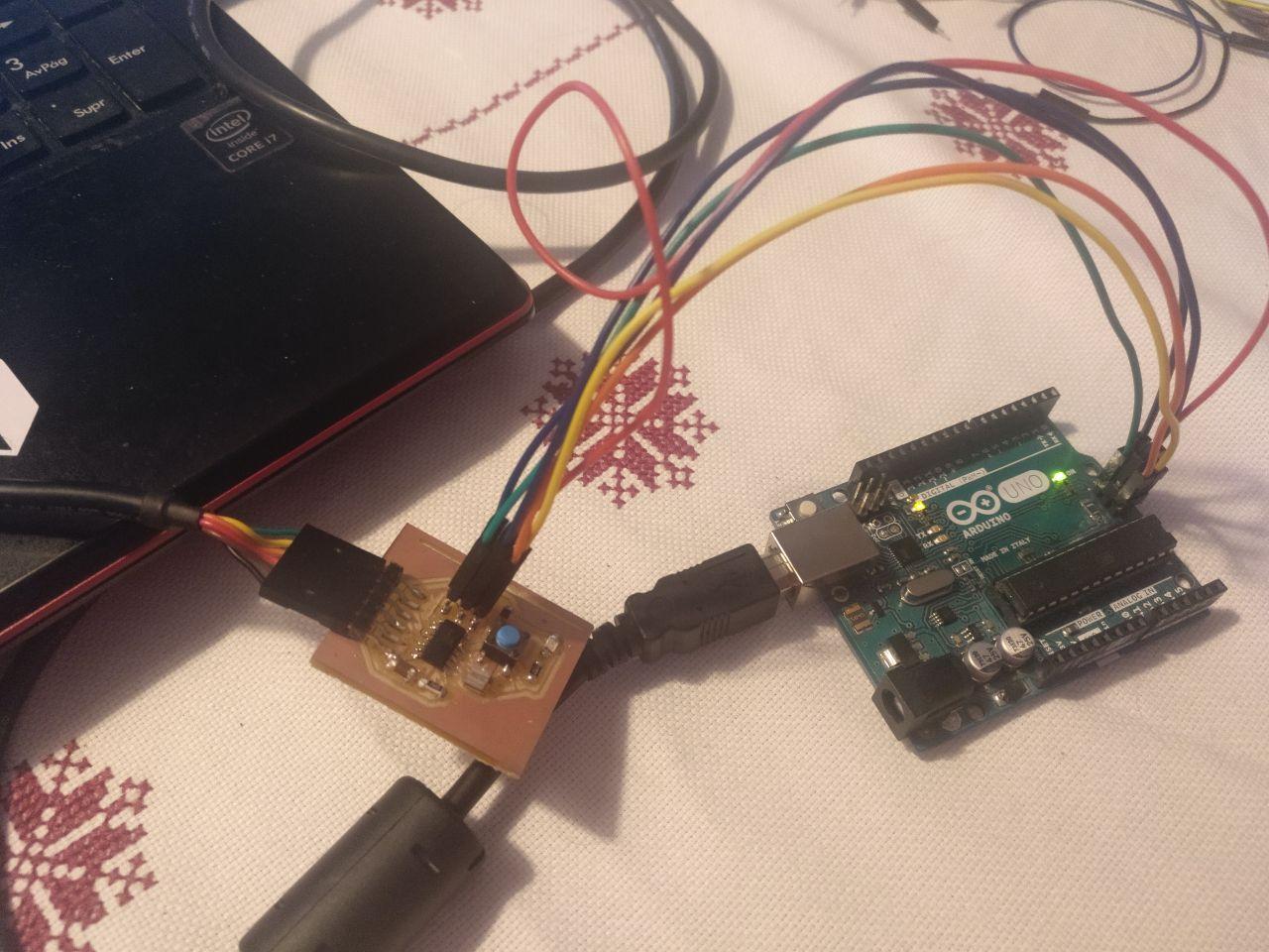
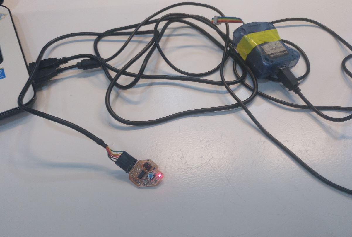
I also tried at home using an Arduino board as a programmer. I had to be realy careful about the wiring.
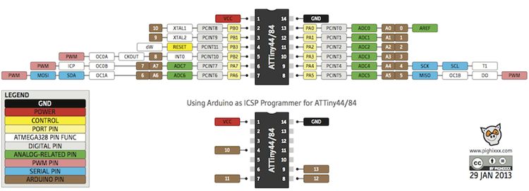
ATTiny pinout. The bottom image are the arduino ports you have to connect your attiny.
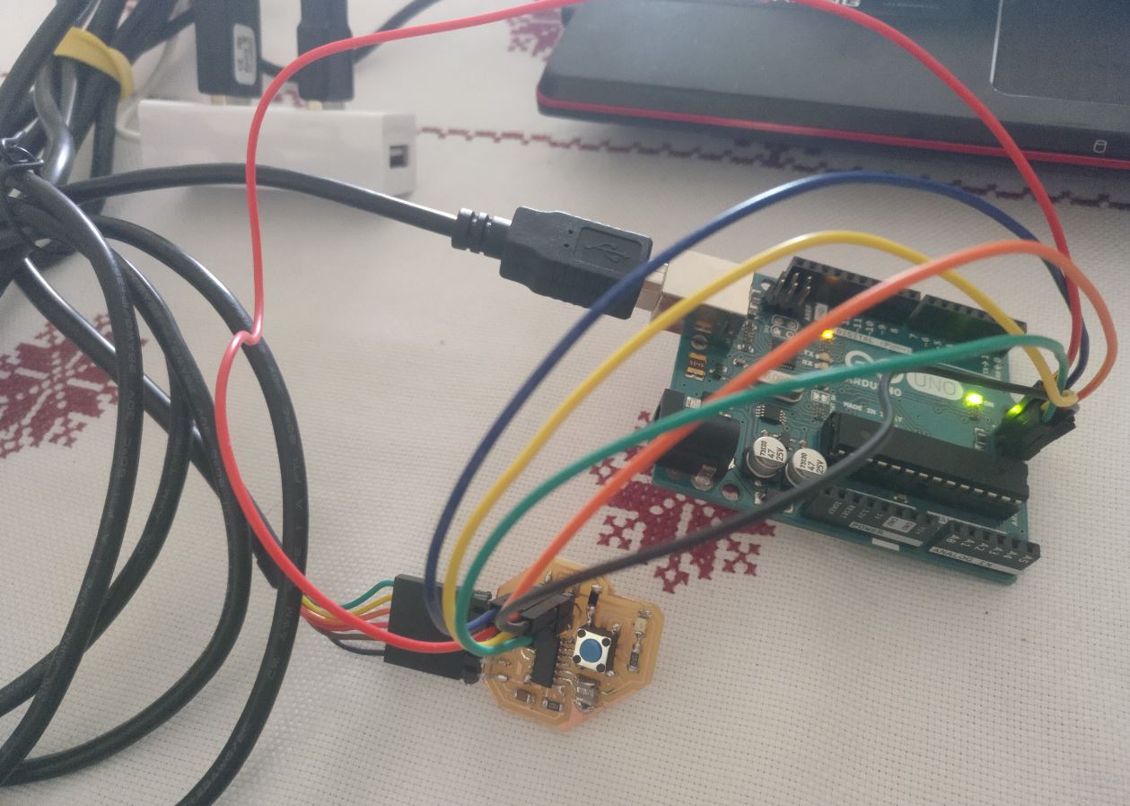
wiring wiring wiring
In both cases I didn’t manage to program the board. It was something else but…
Pause to do the Final Project
I had to pause this to address the Final Project. So after some time and rest (and reaperture of the lab) I could…
Restart
Ok. So now that it’s september I can go back and look what happened in the board and why isn’t working… and thanks to Josep… he realized that… I put wrong the controler. I rotated it 180 degrees.
Rotated microcontroller
So that was the problem. The solution was to unsoldier it and soldier it again. I learn a trick of using a heat pistol (with care) to take out things with lots of legs.
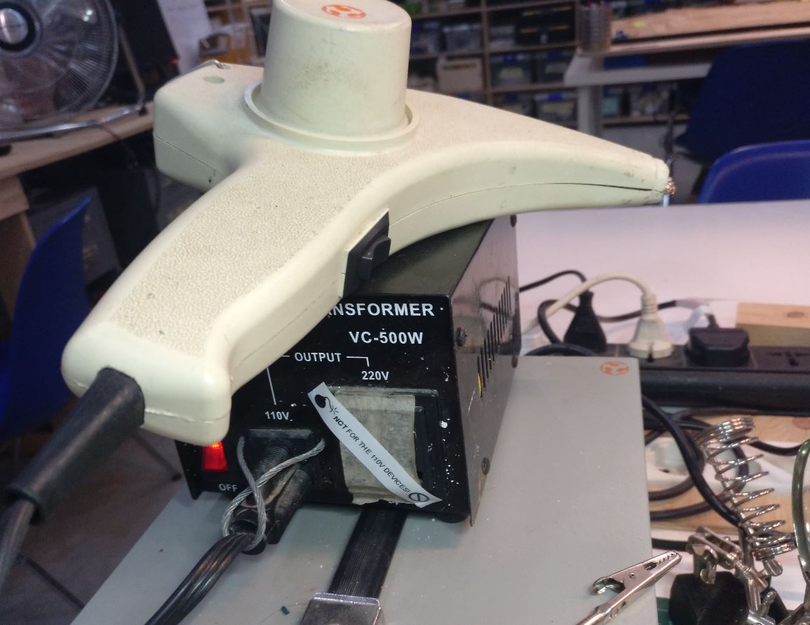
I love the retro-futuristic aeshtetics of this heat pistol
So this was the result. Now I have to soldier it again in the right position. Siiiigh.
Now I’m ready to soldier it again. I almost can hear the microcontroller laughing at me
And this is the result
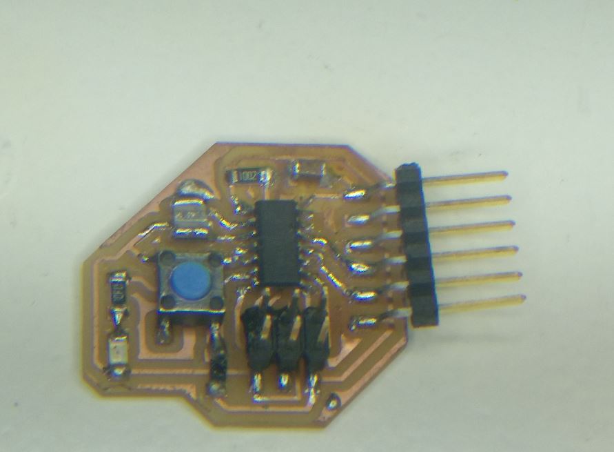
Are you happy now, mr. microcontroller?
Problems with the programmer AVR (MKII)
Now the problem was with the AVR programmer and my windows10 computer (well, my wife’s). There were always kind of problems of not getting the programmer right. And that was annnoooooyiiiiing
If you ever get these kind of errors, the solution I’ve followed was installing the drivers unsigned manually. This is the tutorial (and the files)
https://boseji.com/posts/installing-avrisp-mkii-with-libusb-win32-on-windows10/
It’s long but it gets the job done. With all that now I can program my attiny OR NOT
Simple programming
Ok, for the programming I have a led and a button. And I had all the day trying to make it work, so let’s try something easy.
I tried the the serial echo program by Neil. But probably there is something that I miss (maybe that I have to open the other port to communicate) so I tried the Blink program.
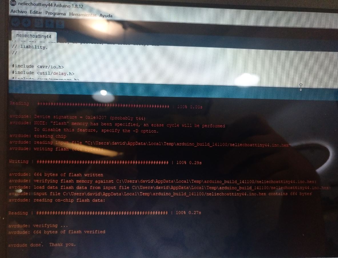
Finally it gets programmed
I go back to the pinout and the 7 was the pin of the LED and the 8 is the pin of the button. So a simple Blink would do.
Problems with the LED
And it was programmed but it didn’t work. We tested and the voltage with the multimeter was varying so the progamming was ok (FINALLY!) but the LED didn’t blink. So back to the soldiering station.
Finally the problem was that the leg in question wasn’t well connected.
The last laugh of the bad microcontroller
After using more wire… and copperbraid I could correct it.
I also modified the program so it only blinked when I press the button (to add any kind of funcionality)
And it worked. Yay!
Hero Shot!
IT’S ALIVE
only blink programming
blink when the button is pushed
Useful links
http://fab.cba.mit.edu/classes/863.16/doc/tutorials/fabisp_programming/#windows
Design files
Remember to use download link as.. to download the files.
Other thoughts
These are notes from the session of April, the 21th.
-
Remember to use a capacitator.
-
Remember that if using connectors, it can be a good idea to have a simmetrical connector with duplicates to reduce the posibility of disconnection. Use something like GND VCC VCC GND
Further design. Attiny1614
This is written after doing the final project presentation and with more knowledge acquired.
Ok, so we’re not done yet. I want to add another board designed by me. And since I hate the ATTiny44 I’ve used (Because what happened and because it doesn’t have serial communication to debug) I want to do a board with
-
An ATTiny1614
-
An input
-
An output
-
As a plus, I2C to connect to the barduino and do stuff
-
An embedded LED.
Starting the design
So the list now is
-
An Attiny1614
-
An UPDI connection
-
An FTDI connection
As a basic. For the output
-
A pin with resistor (220 ohms, but it will be 100 ohms)
-
A ground connection
-
A pin with a resistor and an LED connected to ground.
For the input
-
A pulled down pin so a pin with a connection with ground.
-
A pin to VCC
For the I2C
-
2 pins
-
VCC
-
Ground
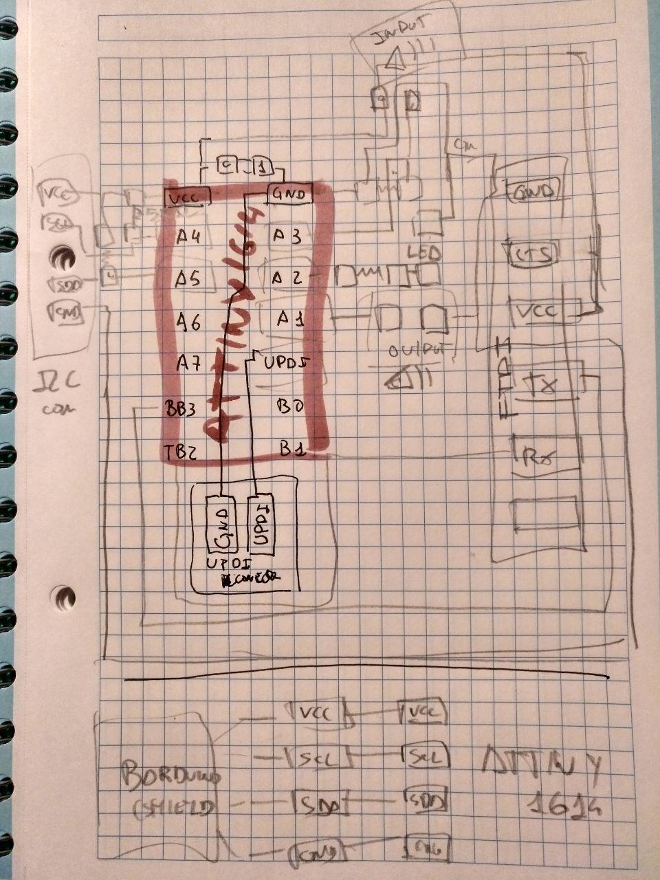
With all that, before going to kicad, I’m going to do a drawing of it. Since I have the Neil’s example I have a glimpse of the scale of it and make a first draft.
And this is it.
Changes of the design
Ok, having the input of Oscar the instructor and also from Adrian from FablabLeon (he showed me the Adrianino he made) I correct some stuff
Looking at this image I can correct some pins that can be better assigned:
Here we can see
-
that the pins that are SCL and SDA are the B0 and B1.
-
That A3 is PWM (so it can be better suited for output)
-
That A2 has an interrupt. So it may be better suited for using the shock input.
Also a doubt that I have is that the I2C has no clear protocol. There is some by grovy that is SCL/SDA/VCC/GND but it’s not that standard so I can play with it because I don’t feel comfortable to have VCC next to ground.

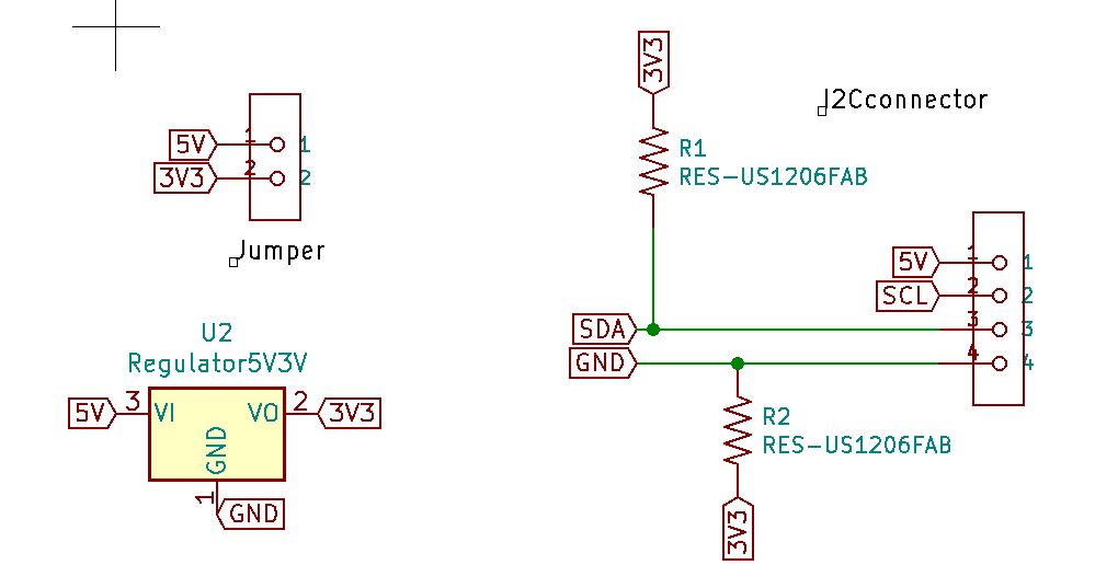
Also there is a problem about the input. Barduino works at 3V3. FTDI goes on 5V. Attiny can go either 5 or 3V3 buut not both at the same time. So maybe put a power regulator for that. Aaaand since maybe also the input comes from 3V3 and the regulator it’s not going to come, let’s add a jumper.
Now I feel more confident going to Kicad
Schema
And this is the schema with several parts done in kicad.
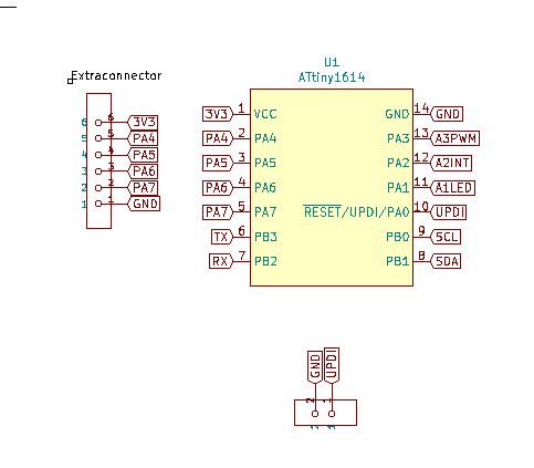
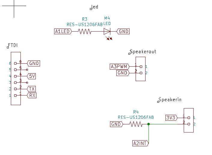
I had to add a capacitor that I thought I added but I didn’t.
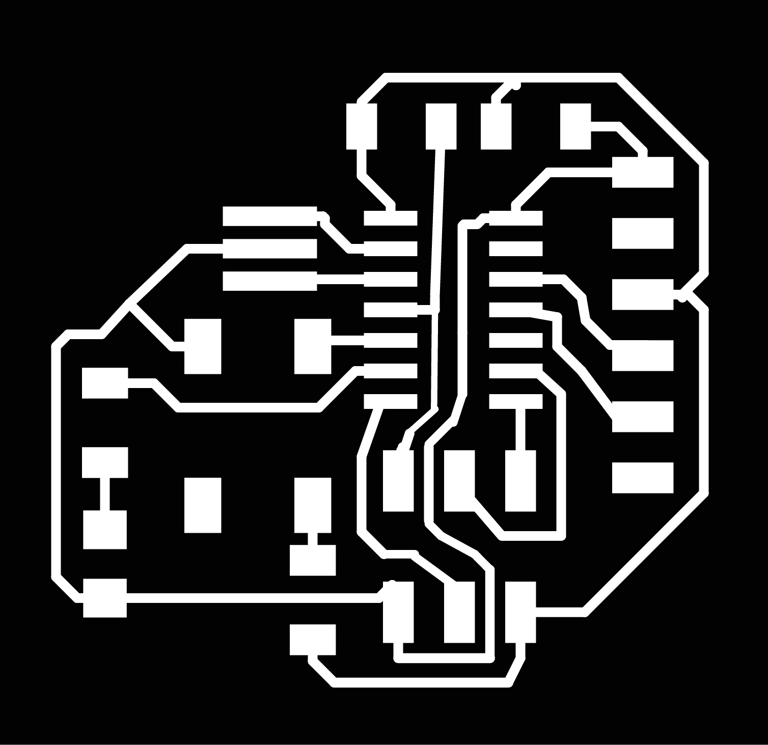
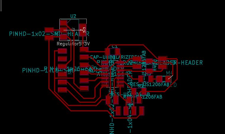
PCB
Then going to the PCB board I untangle the untangable
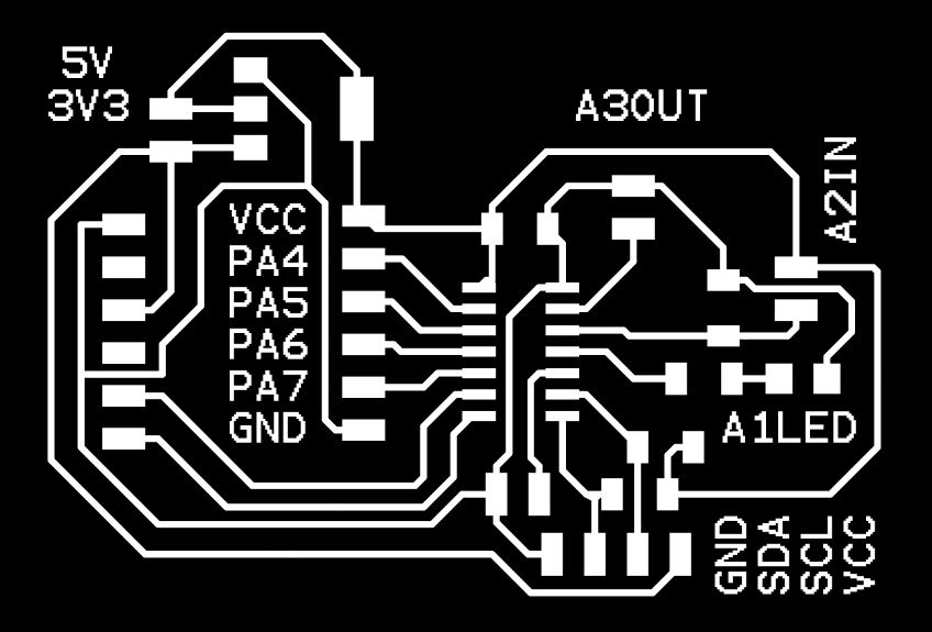
And I add some space because I want to add some text for the David of 2022 who doesn’t want to see this documentation with much care in order to know which pin does what.
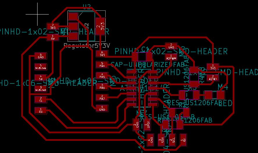
I added the text in Photoshop because it’s easier.
And then go to mods.
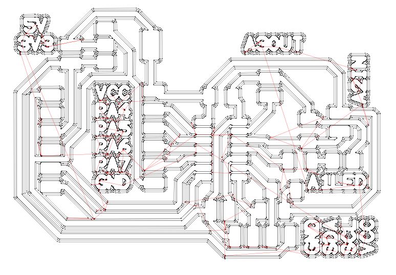
I tried the idea of separating the cuts and make one cut for the text (with 1 offset) and the 4 offsets for the rest of the traces. But they overlap and I wouldn’t read the text. And also the problems took too much time to resolve
Problems
-
I put the wrong machine (I’m milling in a SRM and I put the MDX) and I scaled the drawing by doing that u.u
-
Josep found before cutting a failure wher ethe mods was going to make a shortcut. Fixed in Photoshop and in Kicad.
But now it’s working well. I hope so, at least!
Programming
Here I’ll link back to the programming week to deal with all the shenanigans of programming. And I hope I don’t have to go back here to redesign anything!
It seems that after a long journey I can establish the workflow to program the updi. It’s not the most confortable buuuut…
You can check it out here