9. Embedded programming
In this, the first week of staying at home from the beginning I’m going to try to program as much as I can and connect to several boards I Luckily have at home.
I have at home (thanks to Fablab BCN).
-
An arduino UNO board
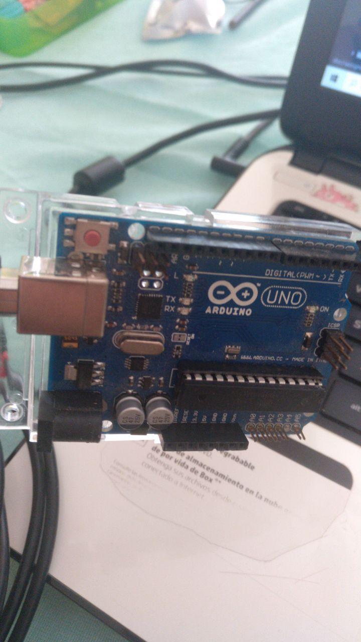
thanks FablabBCN
-
A Barduino board with an ESP32 Wroom that we printed last Thursday the last day we could stay at the Fablab
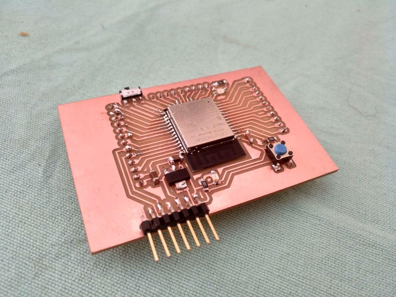
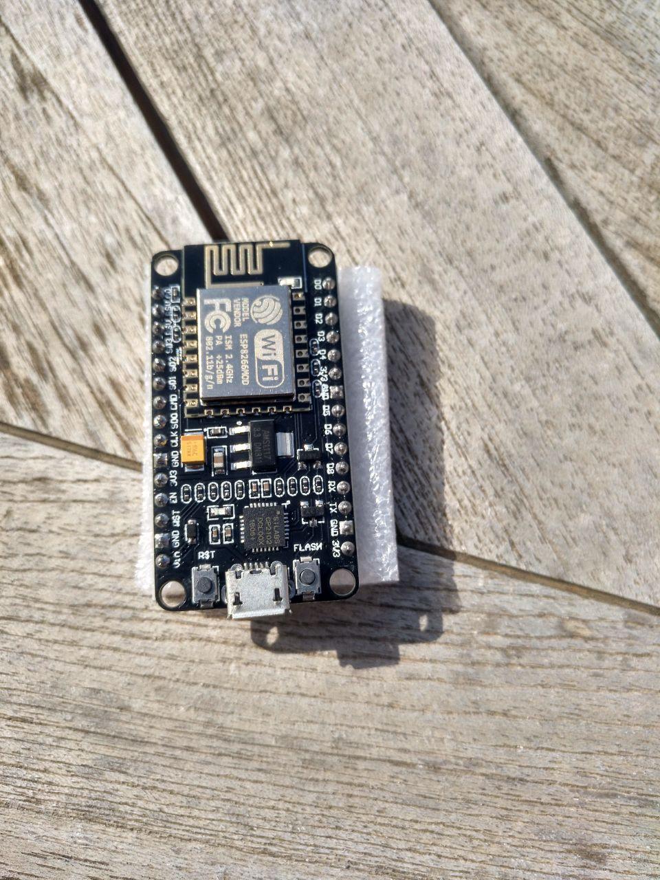
the extra pin was because I didn’t want to break it and have a 5 pin * A NodeMCU Amica.
new from the box! thanks FablabBCN * An ATTiny44 echo board with the button and the led. That one I have to finish soldiering it because I only manage to have the chip soldier.
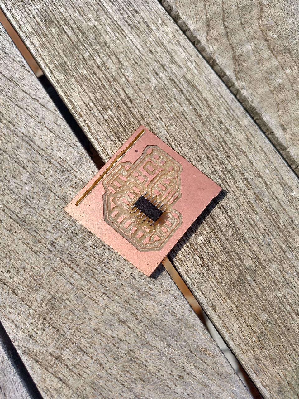
Your time has yet to come, little ATtiny44
We are told about the toolchain and the different programs to make the toolchain from the C code to compiling to upload the code into the microcontroller so I’ll try to start from the easy one to the harder one and learning step by step.
This is an important week for me because my final project it’s a physical videogame, so I need to know what can I do and what I’m not able to do!
Note: My computer and the IDE is in Spanish so the images will be in Spanish and the translations that I’ll do into English can be imprecise.
Arduino UNO start blinking!
First I’m doing arduino UNO, so I installed the arduino IDE. Luckily Neil tell us the different between the different Arduino concepts called arduino.
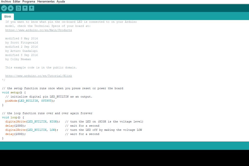
This is the Arduino IDE with the blink demo program ready to launch
In class I tried to make the blink program to work but I couldn’t. I didn’t care about it too much because I had to catch up with the class. But now I have the time to be step by step.
When I plugged it it seems to blink so at least seems that the board is physically all right.
From windows 10 I tried to reinstall the drivers to double check if everything is ok. (in the device administrator with the arduino plugged in correctly in the COM4 and using the instructions from the Arduino web)
Next go back to Arduino IDE.
I found that you can ask the board which board is it if you ask it politely . And by politely I mean that you go Tools-> Get board info. That’s very convenient. Specially when I’m going to work with those ATTiny and the ESP32.
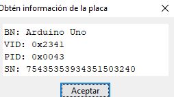 Told you, politeness
Note: with the Barduino and the NodeMCU this didn’t work and it didn’t show which chip is it. = (
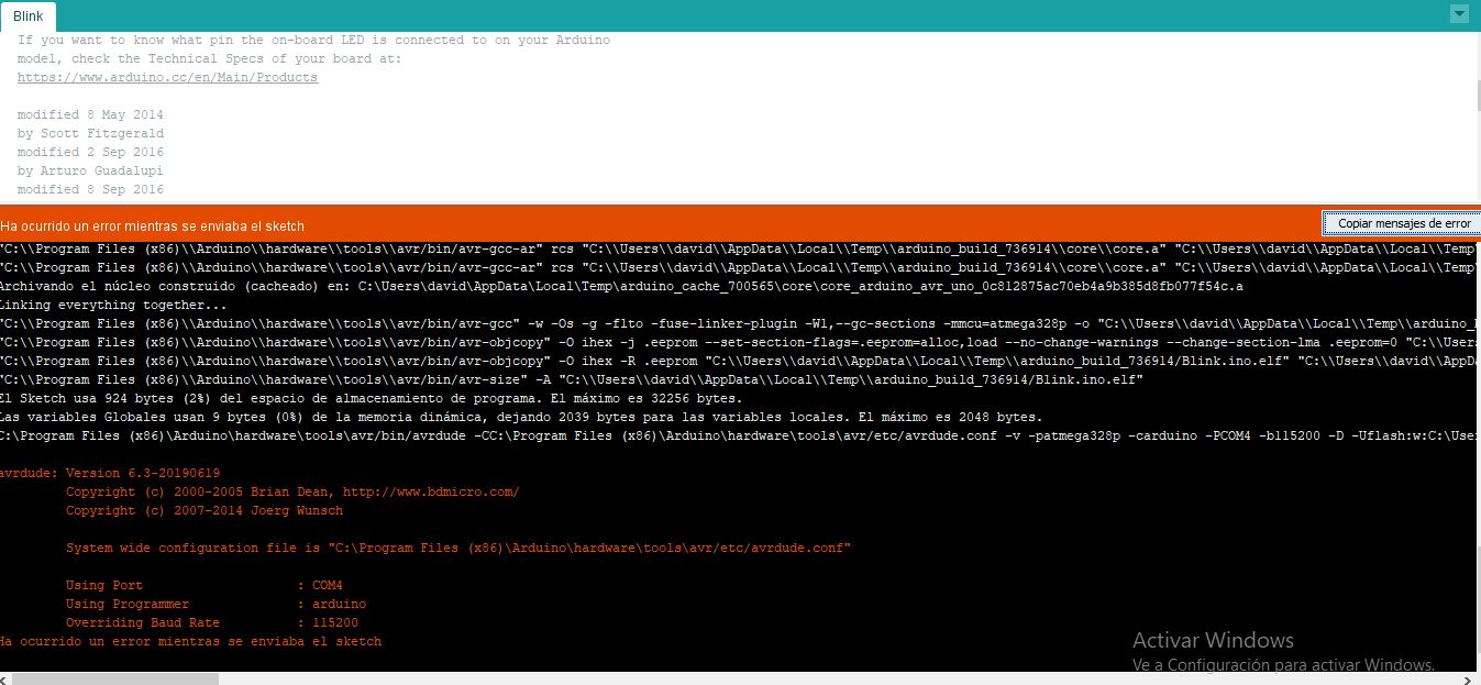
I load the blink program just to test if it works.
Ok, problem sending the sketch file. No more info even if I try to copy more details.
avrdude: Version 6.3-20190619
         Copyright (c) 2000-2005 Brian Dean, http://www.bdmicro.com/
         Copyright (c) 2007-2014 Joerg Wunsch

         System wide configuration file is "C:\Program Files (x86)\Arduino\hardware\tools\avr/etc/avrdude.conf"

         Using Port                    : COM4
         Using Programmer              : arduino
         Overriding Baud Rate          : 115200
Ha ocurrido un error mientras se enviaba el sketch
Trying to press the reset button…
… not working. Same error.
Trying not to use the USB HUB I have…
… not working. Same error.
 Same error. SAD FACE. HULK USES CAPS INSTEAD OF SMASHING BECAUSE SMASH THINGS THESE DAYS IS NOT VERY CONVENIENT
Reading about the bootloader it maybe the answer but the error it gives it’s another one. Also I have the hunch that’s something that has to do with the Baud Rate because it listen and works at 9600 Baud rate but for programming it tries the 115200.
If I check, the Arduino board that I have is an Arduino Uno-R3. If I look for it I can know that has an ATmega328 and the Datasheet is here
I found some equations about the baud rate but it doesn’t seem to be helpful.
I tried another cable since I’ve read that the baud rate depends on the cable length and at least I got another error:
 cuality avrdude: Version 6.3-20190619
         Copyright (c) 2000-2005 Brian Dean, http://www.bdmicro.com/
         Copyright (c) 2007-2014 Joerg Wunsch

         System wide configuration file is "C:\Program Files (x86)\Arduino\hardware\tools\avr/etc/avrdude.conf"

         Using Port                    : COM4
         Using Programmer              : arduino
         Overriding Baud Rate          : 115200
avrdude: stk500_getsync() attempt 1 of 10: not in sync: resp=0x00
avrdude: stk500_getsync() attempt 2 of 10: not in sync: resp=0x00
avrdude: stk500_getsync() attempt 3 of 10: not in sync: resp=0x00
avrdude: stk500_getsync() attempt 4 of 10: not in sync: resp=0x00
avrdude: stk500_getsync() attempt 5 of 10: not in sync: resp=0x00
avrdude: stk500_getsync() attempt 6 of 10: not in sync: resp=0x00
avrdude: stk500_getsync() attempt 7 of 10: not in sync: resp=0x00
avrdude: stk500_getsync() attempt 8 of 10: not in sync: resp=0x00
avrdude: stk500_getsync() attempt 9 of 10: not in sync: resp=0x00
avrdude: stk500_getsync() attempt 10 of 10: not in sync: resp=0x00

avrdude done.  Thank you.

Ha ocurrido un error mientras se enviaba el sketch
For that I changed again the USB cable and touched a little bit. Now it seems that the bootloader is broken afer I consulted the error code in google (here the same problem in Spanish by someone using… windowsXP xD)
Also I found that the rx was not blinking as spected so that was worrying
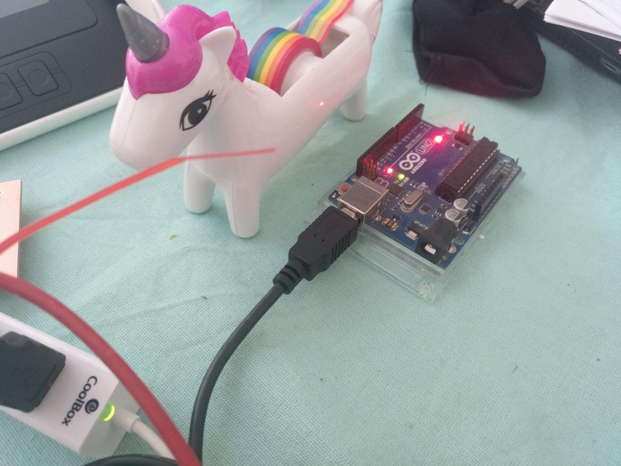 the unicorn feels that something is not right
Now that is a dead end for now (I’ll try to fix that later and program it later) let’s try the barduino board.
Barduino
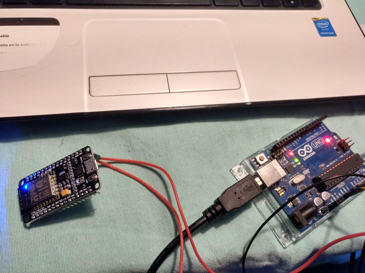
I got a Barduino and I have a USB to serial (6 pins) port but I’m going to try to use a programmer we have since I could bring it home last week.
For some reason, maybe I soldiered it wrong I can’t get to be recognized and the power led is not constant. In fact right now It doesn’t power up. I tried with both serial ports. No results.
I check the connections (diode mode with the multimeter) but everything seems to be right. I also checked if there was a problem of connectivity between the usb but everything seems to be fine.
So let’s try to go to the next board I had from the fablab.
NodeMCU amica
I also have been deliverd the last day another ESP board. In this case a nodemcu AMICA.
Since it’s not a ESP32 but a ESP8266 I had to tell arduino IDE to get the boards definitions. But it was easy using the libraries links we have.
Includes in the Arduino IDE

Copy paste this into Arduino > Preferences... > Additional Boards Manager URLs:

https://raw.githubusercontent.com/damellis/attiny/ide-1.6.x-boards-manager/package_damellis_attiny_index.json
http://arduino.esp8266.com/stable/package_esp8266com_index.json
https://raw.githubusercontent.com/espressif/arduino-esp32/gh-pages/package_esp32_index.json
https://adafruit.github.io/arduino-board-index/package_adafruit_index.json
http://drazzy.com/package_drazzy.com_index.json
https://www.mattairtech.com/software/arduino/beta/package_MattairTech_index.json
https://dl.espressif.com/dl/package_esp32_index.json
https://mcudude.github.io/MiniCore/package_MCUdude_MiniCore_index.json
https://dl.espressif.com/dl/package_esp32_index.json
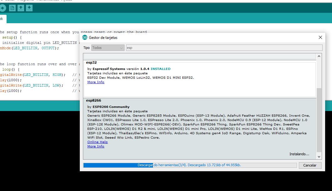 Thank Goddess that we have access to all those links provided by the fablab crew
I tried again with the led blink example from the arduino. And ind this case, it worked!
tears of joy
I also made the test using the arduino as a power source plugging the pins of 3v3 v and ground. (for now the Arduino it’s the only thing it can do)
 Arduino turned to a battery and at least it worked and the NodeMCU works properly
I noticed that the consumption was over the reasonable for a led blinking program. Probably because what we have been told in class about the extra layer of abstraction of arduino has a cost in terms of speed and memory usage.
In another session I’ll go deeper into that.
Useful links
After the assigment
After the assigment that I did I want to keep track of the expriments I want to do before I go on
First I’m going to try a echo script in the nodeMCU, after that I’m going to make the Barduino work. Then I’m going to try platform.io.
Echo script
Since I’d need some feedback to sense stuff I want to make sure that I can make a simple echo program.
In the Neil’s class I found a code for ESP8266 that’s the NodeMCU that I have.You can see it here
I mixed the code with the blink code so I hope if I can merge code and not just copy it.
This is the code
// the setup function runs once when you press reset or power the board
void setup() {
  // initialize digital pin LED_BUILTIN as an output.
  pinMode(LED_BUILTIN, OUTPUT);
     Serial.begin(115200);
}
#define max_buffer 25

// the loop function runs over and over again forever
void loop() {
     static char chr;
   static char buffer[max_buffer] = {0};
   static int index;
   if (Serial.available()) {
      chr = Serial.read();
      Serial.print("hello.ESP-01.echo: you typed \"");
      buffer[index++] = chr;
      if (index == (max_buffer-1))
         index = 0;
      Serial.print(buffer);
      Serial.println("\"");
      }
  digitalWrite(LED_BUILTIN, HIGH);   // turn the LED on (HIGH is the voltage level)
  delay(500);                       // changed
  digitalWrite(LED_BUILTIN, LOW);    // turn the LED off by making the voltage LOW
  delay(1500);                       // changed
}
And it works!
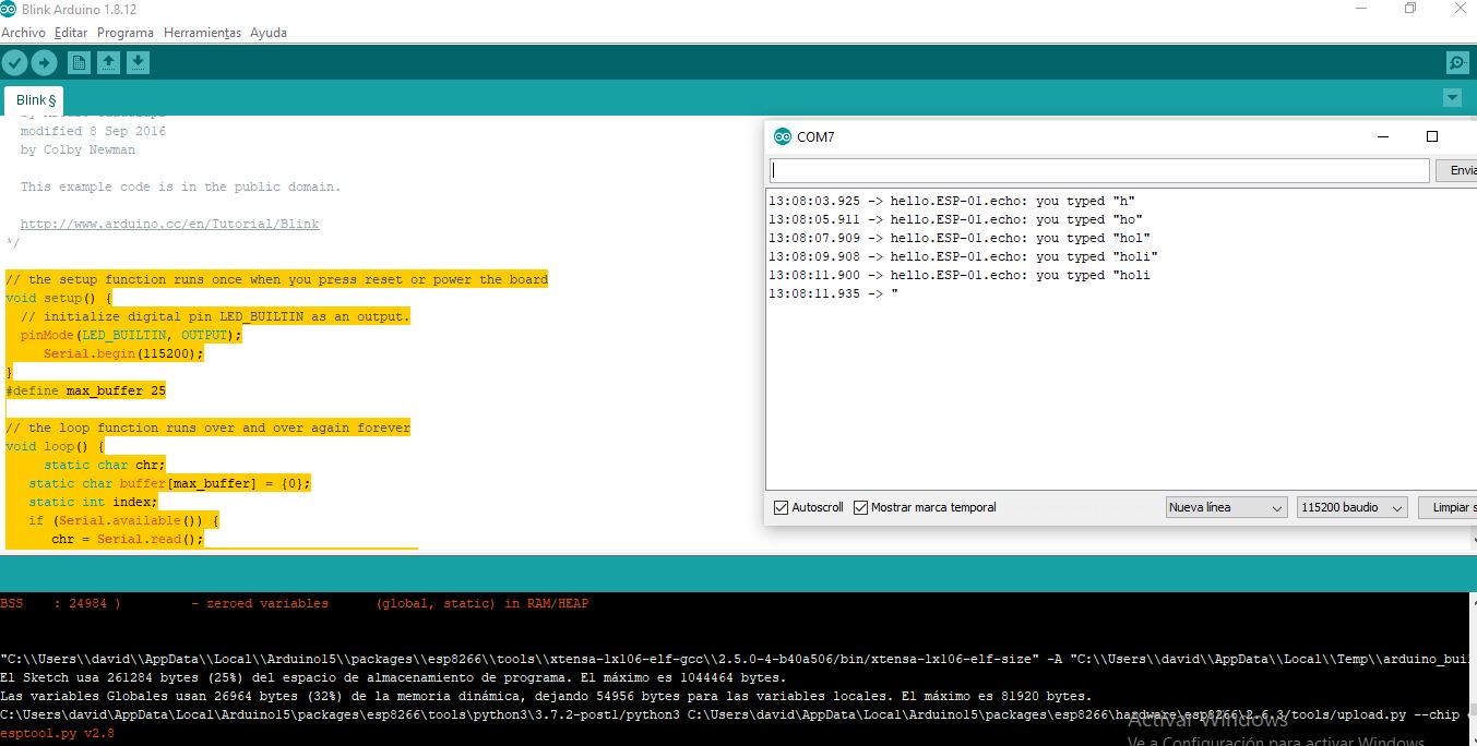 I really like that this goes well at first try
when I open the port it works properly so cool! The only issue is that since we have delay, the answer takes 2 s so maybe I have to refactor a little bit.
I tried to refactor it so it answers every 0,5 seconds and it works! Yay.
See the difference in the timing of the answer
Here is the code:
// the setup function runs once when you press reset or power the board
void setup() {
  // initialize digital pin LED_BUILTIN as an output.
  pinMode(LED_BUILTIN, OUTPUT);
     Serial.begin(115200);
}
#define max_buffer 25

void echo(){
       static char chr;
   static char buffer[max_buffer] = {0};
   static int index;
   if (Serial.available()) {
      chr = Serial.read();
      Serial.print("hello.ESP-01.echo: you typed \"");
      buffer[index++] = chr;
      if (index == (max_buffer-1))
         index = 0;
      Serial.print(buffer);
      Serial.println("\"");
      }

  }

// the loop function runs over and over again forever
void loop() {
  echo();
  digitalWrite(LED_BUILTIN, HIGH);   // turn the LED on (HIGH is the voltage level)
  delay(500);
  echo();
  digitalWrite(LED_BUILTIN, LOW);    // turn the LED off by making the voltage LOW
  delay(500);
  echo();
  delay(500);
  echo();
  delay(500);
}
It’s just a separate function of “echo” that it’s called in different steps of the main loop.
With that I think I can handle the inputs week and go back here when I have more confidence.
Trying to make the ESP32 barduino work
I had some problems with the Barduino 2.0 that I had soldiered. I seems that the problem is with the cable and the conexion to the board. Now with more calm I tried to make it work again.
It’s important to know that in terms of Arduino IDE, this board is a ESP32 dev module
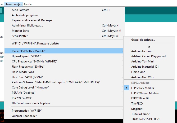 remember that you’ll need libraries to see that kind of boards
After that I tried to compile a blink program but I couldn’t make it. Even if I tried to call the pin IO13, the proper name is only ‘13’. Luckily, Benjamin did it before so I could learn from him.
Platform io
One of the things I wanted to try if I had the time (that I do have now) is trying platform io to upload and checkout code apart from arduino IDE.
To do that I’m following the instructions from the local documentation from Barcelona here
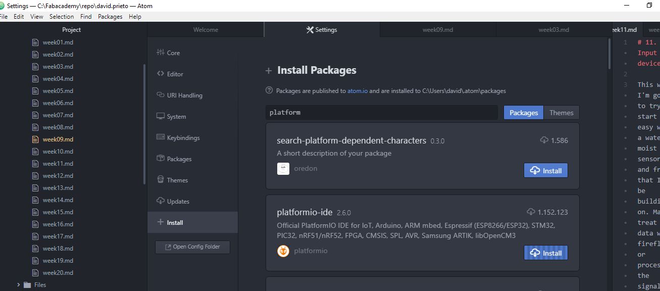 to find platform io in atom
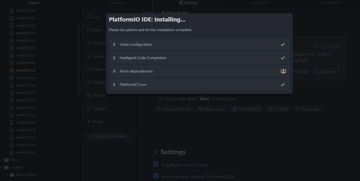 long install is long
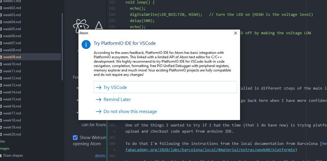
You can install it with pip install (since I have Python already installed) and the IDE can be found in the package searcher of atom (that I already have). I takes a long time and you need another installation of LLVM that weights 500 MB but it seems to work. But the webpage and the package itself discourage you to use it and try platform io for Visual Studio Code instead.
 When you install something and it tell you that you should have installed something else is annoying
Even the automatic installation seems to me a little hard and annoying if you compare it to arduino IDE.
But ok, let’s move on.
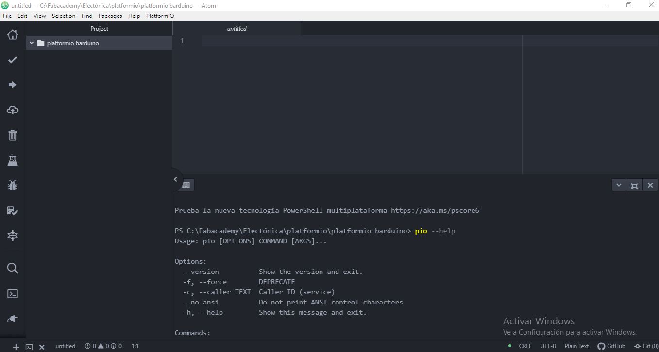
I’m following the instructions from here to make the project of the board ARDUINO.
So now that I have a Barduino working, I can try to use it.
the platformio ide with the terminal embedded
Now I make the new project with the platformio ide extension. I know there is the option of the shell (Benjamin used it).
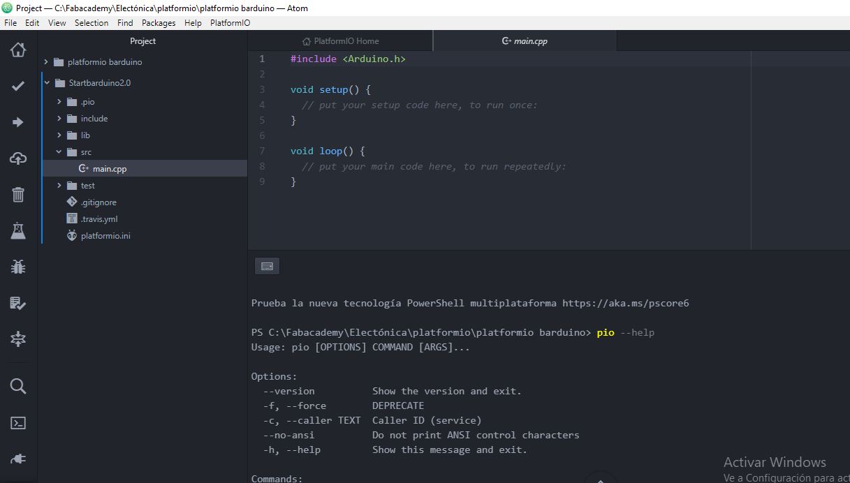
the program in /src waiting to be done and uploaded
Now I have a new blink program to upload
/**
 * Blink
 *
 * Turns on an LED on for one second,
 * then off for one second, repeatedly.
 */
#include "Arduino.h"

// Set LED_BUILTIN if it is not defined by Arduino framework
// #define LED_BUILTIN 13

void setup()
{
  // initialize LED digital pin as an output.
  pinMode(LED_BUILTIN, OUTPUT);
}

void loop()
{
  // turn the LED on (HIGH is the voltage level)
  digitalWrite(13, HIGH);

  // wait for a second
  delay(200);

  // turn the LED off by making the voltage LOW
  digitalWrite(13, LOW);

   // wait for a second
  delay(200);
}
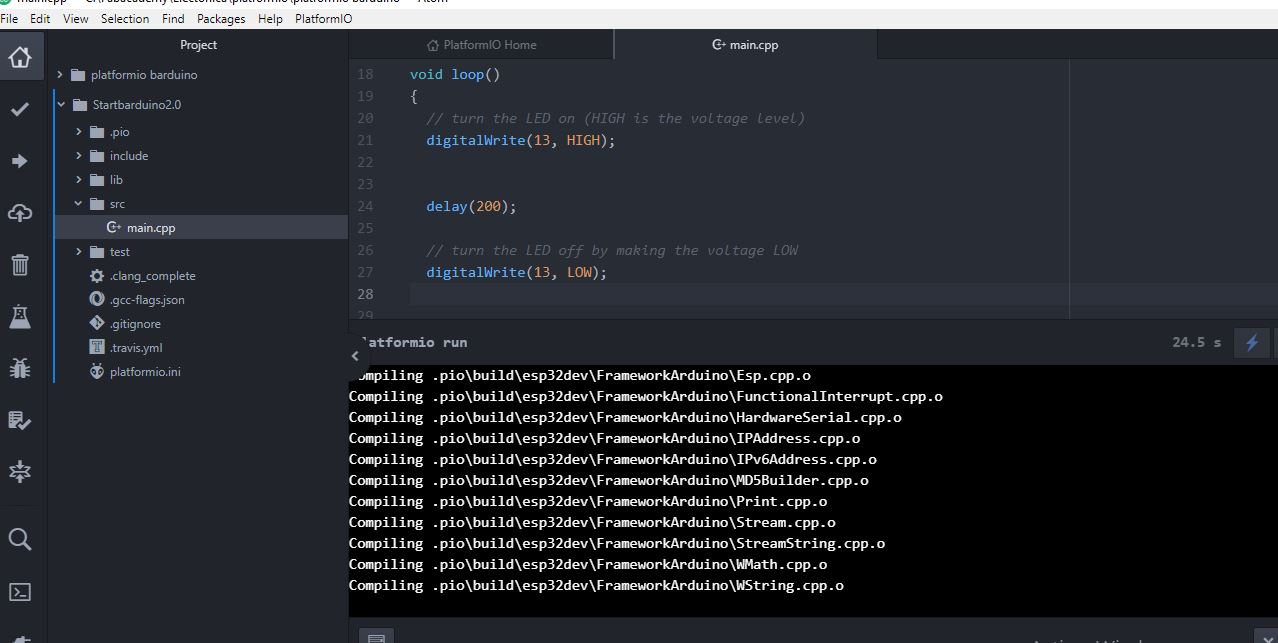
changed to be a delay of 0.2 s and be the 13 pin that’s the good one in the barduino 2.0
After done that, you press build with the gui or the shell commands. That performs a pio run command.
 the shell closes if there is no error by default
- Also it seems that these programs take less space here than using Arduino IDE.
Then you press upload. If you don’t have the extensions, the program will download it and try to autodetect the correct port by itself (unlike arduino IDE)
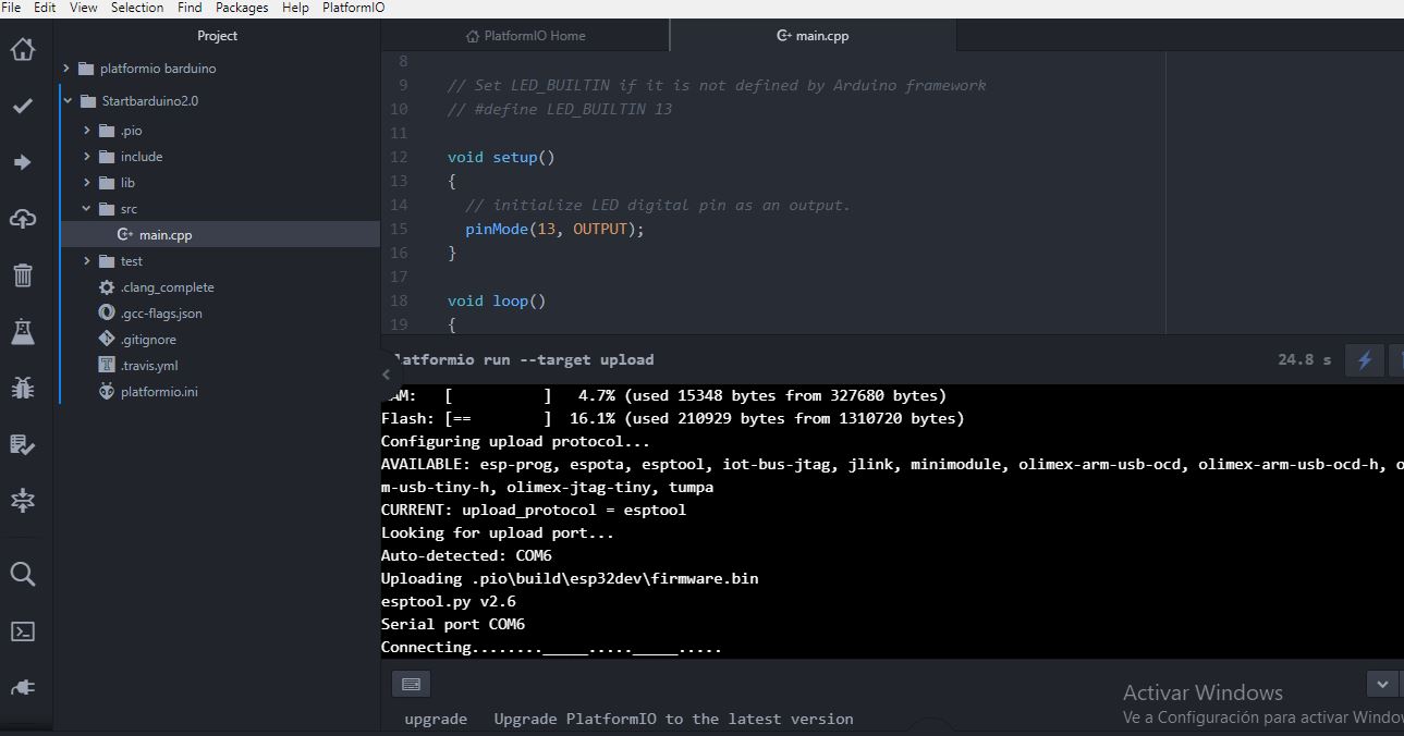
The auto-upload also worked well, but my barduino 2 has problems with the soldiering in the connection. So I had to soldier it back. Done that, it works just fine.
yay!
Platform.io upd8
When I was in the output week I realized of something important about the platformio work model. What it’s in the src folder it’s going all to be compiled and uploaded. So if you have several sketches it’s better to make a new directory to store them an modify the main.cpp. If you don’t you probably will get compiling errors such as “several setup definitions”.
Platform.io upd8. Too heavy for a little computer.
I uninstalled platform.io packages for Atom. The last days I was using it it was not answering properly and I found problems with the libraries (even with installed ones). Specially with the ESP8266. Sometimes I had problems uploading the sketch (and I’m not using specially heavy sketches yet). So I went back to Arduino IDE.
Also the plugings loaded every time I run Atom, and the computer where I installed it it’s a little old so it took long time of opening so I finally I said goodbye to platform.io. If I install it again I’ll use the recommended Visual Studio version and a more powerful computer.
Baudios del flasheo.
9600
when using serial communication with ATTiny 44
Remember that this has to use serial by software and check the rx and tx pins to be the proper ones. (it’s just a couple of lines)
Extra ball ATTiny 1614
This is written after doing the final project, redoing and upgrading the assigments.
Ok, I have the ATTiny44 working. But since I’m used to the ESP32 the ATTiny is a pain to do anything more complex than a blink. Not because it may not be capable, but because I don’t like to make a serial by software to debug things. I prefer to play with something I can debug properly.
And I have an input and an output assigment that include the designing of a board with a microcontroller. So let’s try to to see what can bring us the ATTiny 1614 that seems pretty cool and not very difficult to soldier.
Research links
Ok, I’ve seen Adrián documentation and seems that what I’m doing is fitting. Programming via UPDI while powering up with ftdi seems something that I can do. Maybe I can program something and I can program something that I can embed with the Monolith. But befor let’s starts.
I also looked into Quentin Bolsee docs so I got general information about it.
I installed the library on Arduino IDE called megaTinyCore. I hope it works.
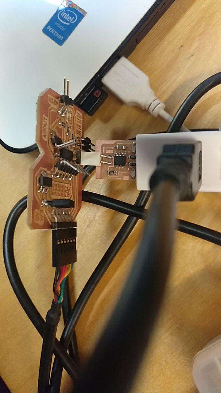
I also looked in the schema of the echo board.
(source: https://github.com/SpenceKonde/ATTinyCore):

It doesn’t seems too hard. Lot’s of pins to use. Serial communication. UPDI. I hope it works!
Here in the week of electronic design I’m going to talk about the board.
Programming once the board is designed milled and assembled.
Ok, now I have these programmers and a couple of FTDI/usb cables. So let’s start programming a simple blink. The pin of the blink is A1. (Not recognized as 1 u.u )
I use the FTDI programer with the converter to UPDI that was my first board ever soldier (and more simple because it doesn’t have any microchips)
I reinstall the megaTinyCore because I’m in other computer. I set the ATTiny1614 basic settings and… let’s try.
And some wild java null pointer exception appears in the grass.
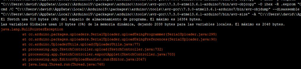
Ah, seems that I had the programmer in the AVR programmer MKII.
No, it’s not that. Let’s try to follow this advice
https://forum.arduino.cc/index.php?topic=690045.0
No, it’s not that.
Let’s try to change the programmer?
um… the updi programmer doesn’t work either. At least I have another error.
I have to talk to Oscar U.U
Installing py udpi, I think I had it for some reason. Donwload from here: https://github.com/mraardvark/pyupdi
Programming through UPDI is a mess
Ok, I figured it out. What you need is a programmer of ftdi and a updi adaptor and another ftdi connected to the same ground.
Or you can have a UPDI direct programmer. But in this case you have to know that your programmer works. Mine had a problem with the FTDI chip and it didn’t work. At all. We discovered it, later. It was a mess.
Now I understand why Adrian in his version added a 3 pin connection so they could program and power up. I should have done the same. And one adaptor from UPDI+VCC to FTDI.
And this is the setup. Beware of how the pins have to be plugged.
messy is the word
Once you have that and with the ground in the proper position, you go to arduino and using the board you just compile the program. But you don’t upload it. That would be too easy
Instead you have to install pyupdi. Since I don’t know why, my pip doesn’t like to install it from the command control, I download it and keep it somewhere I can find it later.
Then I follow what Quentin Bolsee wrote in his programming week
Then I go to % Temp % to locate the hex file the arduino prdoduced. And copy the location.
And then I go to the folder where I downloaded the pyupdi write CMD to open the console in that same folder and write
Python pyupdi.py -f <file.hex> -d tiny1614 -c <COM_port> -b 9600 -v
Being the file.hex the location and the com port the com port detected written like COM5 or COM3
Then it works. Finally.
Hero blink shot
Now to program other stuff!
Comparing workflows (kind of group asssigment)
For me, the easier toolchain are those that have the ftdi chip incorporated. So you only have to plug them. NodeMCU and the new barduinos (that have ftdi chips) are on those categories.
After that using a barduino and programming with a ftdi programmer and cable is… ok. Because you can get those cables.
Then programming through ISP or UPDI is a mess.
That considering just the boards. In terms of IDE
Using platform.io is a mess because I installed embedded in my Atom (that I also use to document) and made it slower to launch and use it because it has all the tools. Even if was only documenting. I uninstalled it. But maaaybe it’s useful embedded in Visual Studio Code and maybe is more useful with Pyupdi.
Arduino IDE is not the ULTRA POWER SHINY enviroment but it’s nice enough.
Looking into the platformio for UPDI
I considered installing back platform.io Here you can find a couple of links that may be useful
https://community.platformio.org/t/programming-attiny1604/11875
https://community.platformio.org/t/custom-upload-protocol-defined-from-board-json/16201
But the conclusion I read is… h4ck platformio. And I’m too lazy to h4ack platorm.io. So I prefer to keep with the manual pyupdi…