4. Computer controlled cutting
This week assigments divides into 3 parts:
-
Group assigment
-
Vinyl cutter
-
Laser Cutting - Press-fit Construction Kit
Group assigment
I worked with Tue, Antoine, Arman and Benjamin and Tue made the full page that you can see in her page:
What I have learnt from the group assigment.
-
To focus the laser machine (I’ve used these kind of machines before but I’ve never focused it!).
-
The importance of usin the caliber to actually measure the material.
-
Kerf matters for precision works.
-
The Test file from previous years is awesome.
-
The controller of this machine it’s quite special because when it says “engrave” it means “rastler” and to engrave you need to “cut” (with different parameters) and it’s sometimes very difficult to explain.
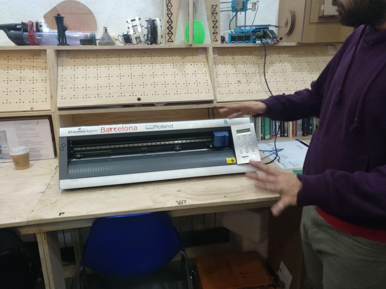
Vinyl cutter
For doing the assigment I used the vinyl cutter that we have at our disposal in the lab (well, the large one) that is a Roland CAMM-1 GX-24 24’‘ Vinyl cutter.
 cut cut cut
Characteristics of the Vinyl cutter
I took them from here (Spanish)
Load material width: 50 to 700 mm Maximum cut width: 584 mm Maximum cut length: 25 000 mm
Maximum cut speed: 500 mm/s Resolution (software): 0,025 mm/step
Workflow
The workflow is at follows: -You have your drawing and you make a raster file or a vector file (.eps or .ai) -You tweak it in the Roland software. -Then you check the machine. In this case that you have the material you want to cut hold in place. The blade works, the zero is set (if needed) -You check back again in the Roland software (measuer twice, cut once) -Send it.
Let’s get things cut!
For this I used a design that was inspired in a card game that I love: Netrunner. First I took the image of a fanart I made of an AI called “Eater” in pixel art. I’ve used the “vectorize pixel art” tool of Inkscape.
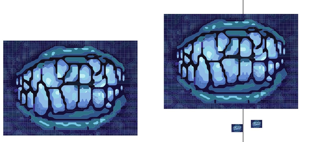 Eater drawing and it’s vectorization in inkscape.
That’s too complex for the vinyl cutter. Because I know well the laser cut I knew that this wasn’t to outcome properly in time.
I made a credit inspired in the originals from netrunner and from the community that keeps it alive (NISEI).
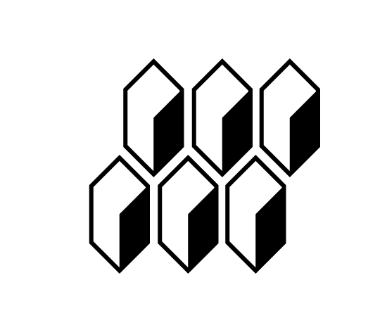 They look nice. They represent money
Even if it’s kind of easy to do with Illustrator, I had to tweak a bit before sending to the cutter (make outlines tool can be kind of tricky). Because if I pressed ctrl+Y this is what I saw
This has problems to be cutted
In this case, the knife was going to pass several times for places I wanted to be passed once. So I had to make contours from shapes and tweak a little bit more in illustrator to see this:
This is better.
Once I’ve sent it it was ammazingly cut. I think this can be useful for my final proyect to make shapes that have to be painted easily using tape. And this is easier to handle than the laser cutter (even if I love laser cutting)
Result
Laser Cutting - Press-fit Construction Kit
Idea
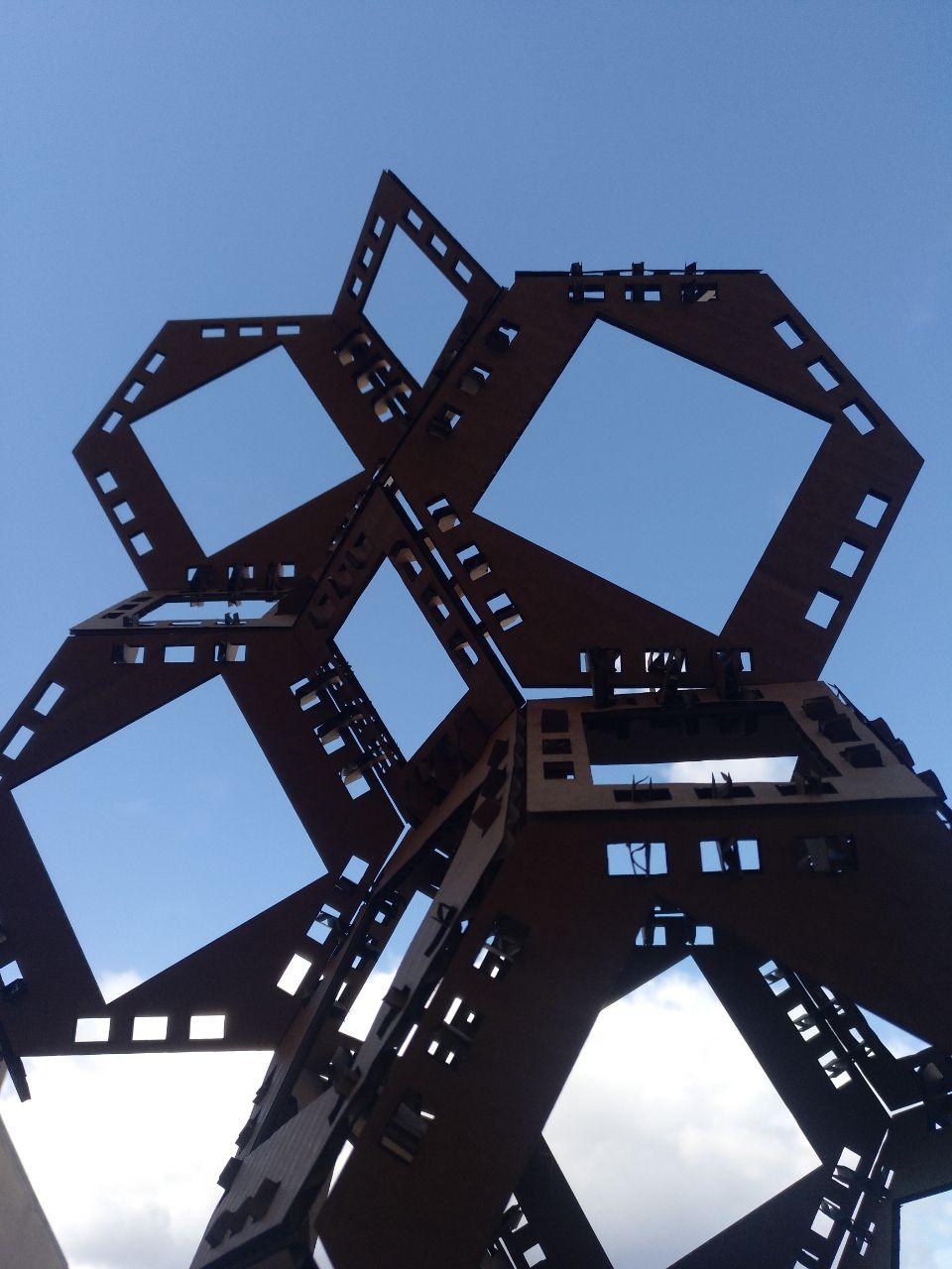
In this case I was interested in some space tesellation. You can see the full project in the project tab (Space tesellation) but here it is as well.
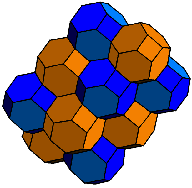
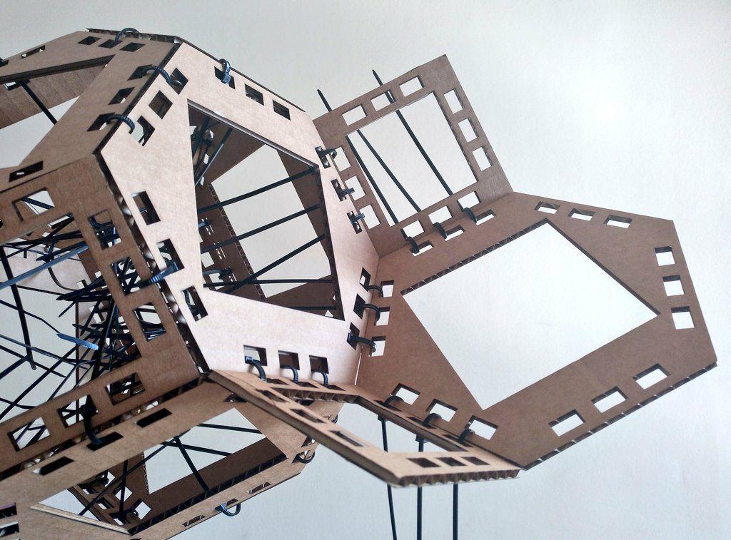
I wanted to copy the tesellation of the plane you can do with hexagons in a honeycomb or with several paterns of polygons. I wanted to make it the next level and avoid using cubes or prismatic shapes (that are the solutions of the 2d plane but extruded) so I stumbled upon the truncated octaedra. This poliedric shape consist on 6 squares and 8 hexagons with the same side. And putting next to each other you can fill the space in several dimensions.
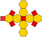
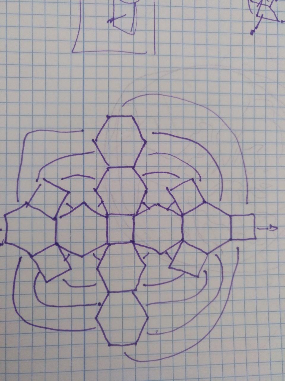
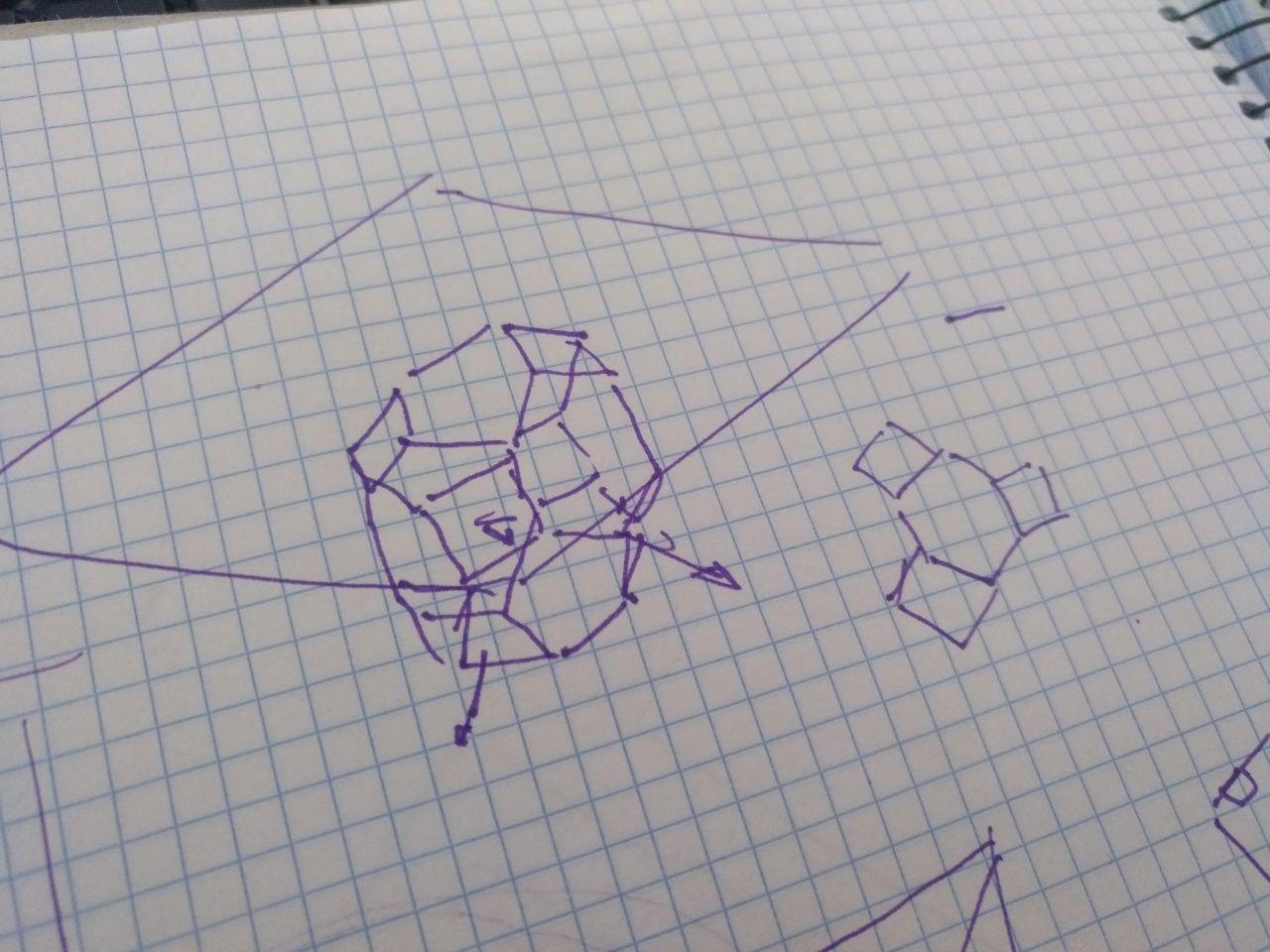
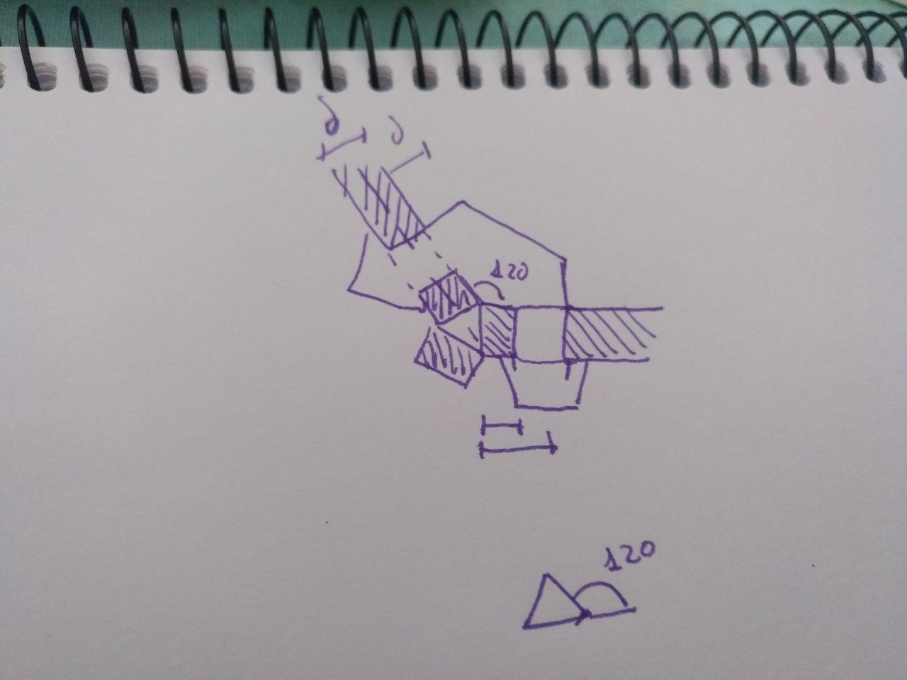
Skeches and first drafts undestanding the geometry:
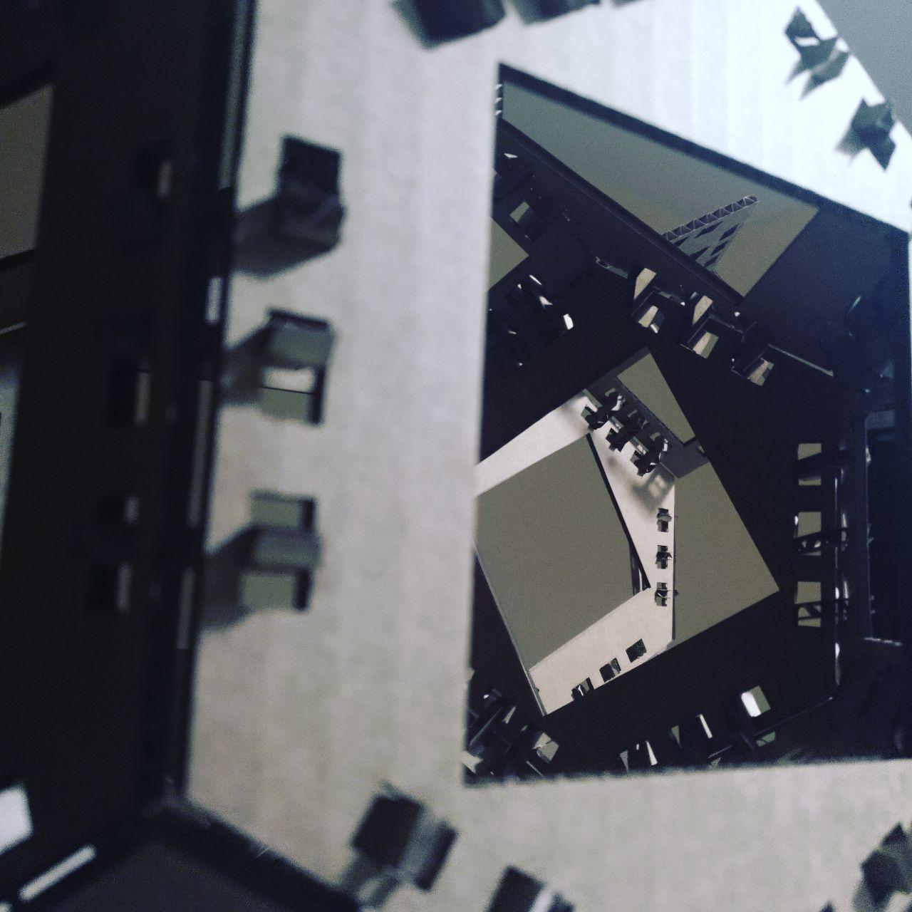
Result
Some final abstract images:
Process
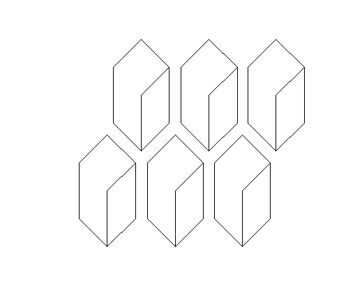
I wanted to do some spacial prototipe and go away from the Usual H-shaped joints. So I imagined some hexagons and sqares joint with plastic brackets. So they will be lasered cutted with some holes to fit the plastic brackets that will join the edges.
 this is the prototipe I did later that was what I was thinking at first but wasn’t enough
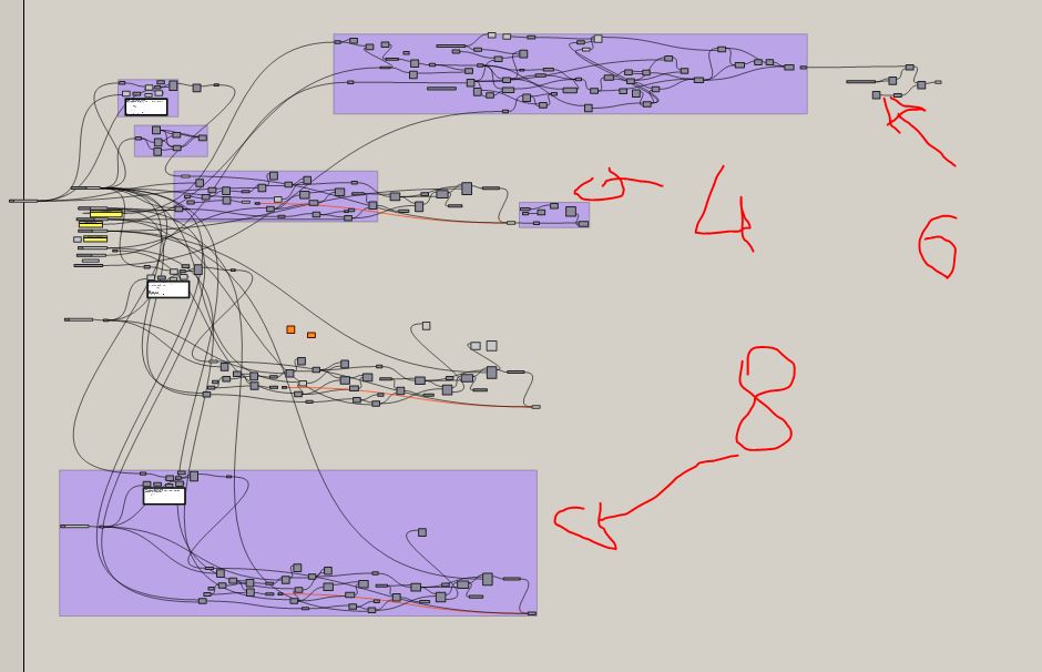
So to make the parametric design I thought of faces interconected side by side with auxiliary plastic connectors. And I made the grasshopper to make these shapes n-sided with n holes to interconect the brackets.
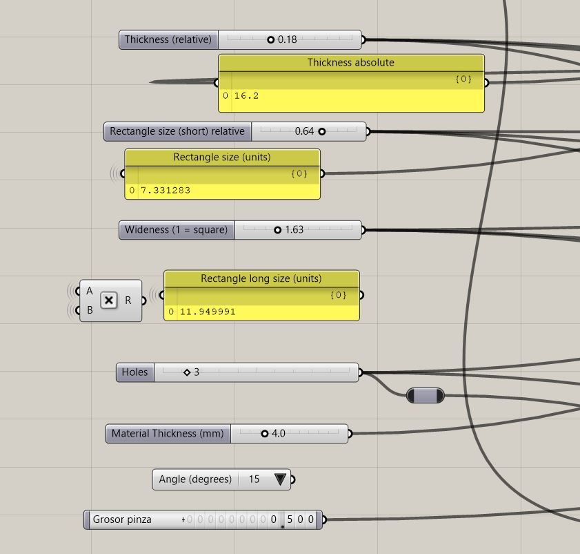
Parameters of design
The parameters where the following:
-
Length of the side
-
Number of holes
-
Dimension and position of the holes
-
Number of sides
As soon as I told this to the instructors they told me that this doesn’t fit the assigment.

Going after something that fits the assigment!
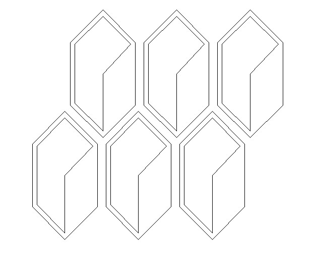
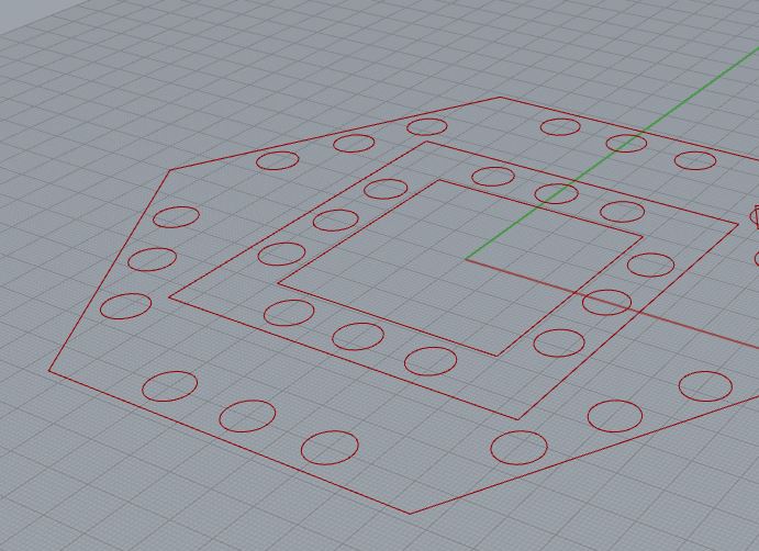
After coping with it. I went back to grasshopper to change and improve my design. I could keep good part of the design and build on that. Instead of doing some circular holes, I can draw rectangles and afterwards design the joints that could be clicked.
(make those rectangles align to the sides was tricky)
Parameters of design
- Length of the side
- Number of holes
- Dimension and position of the holes
- Number of sides
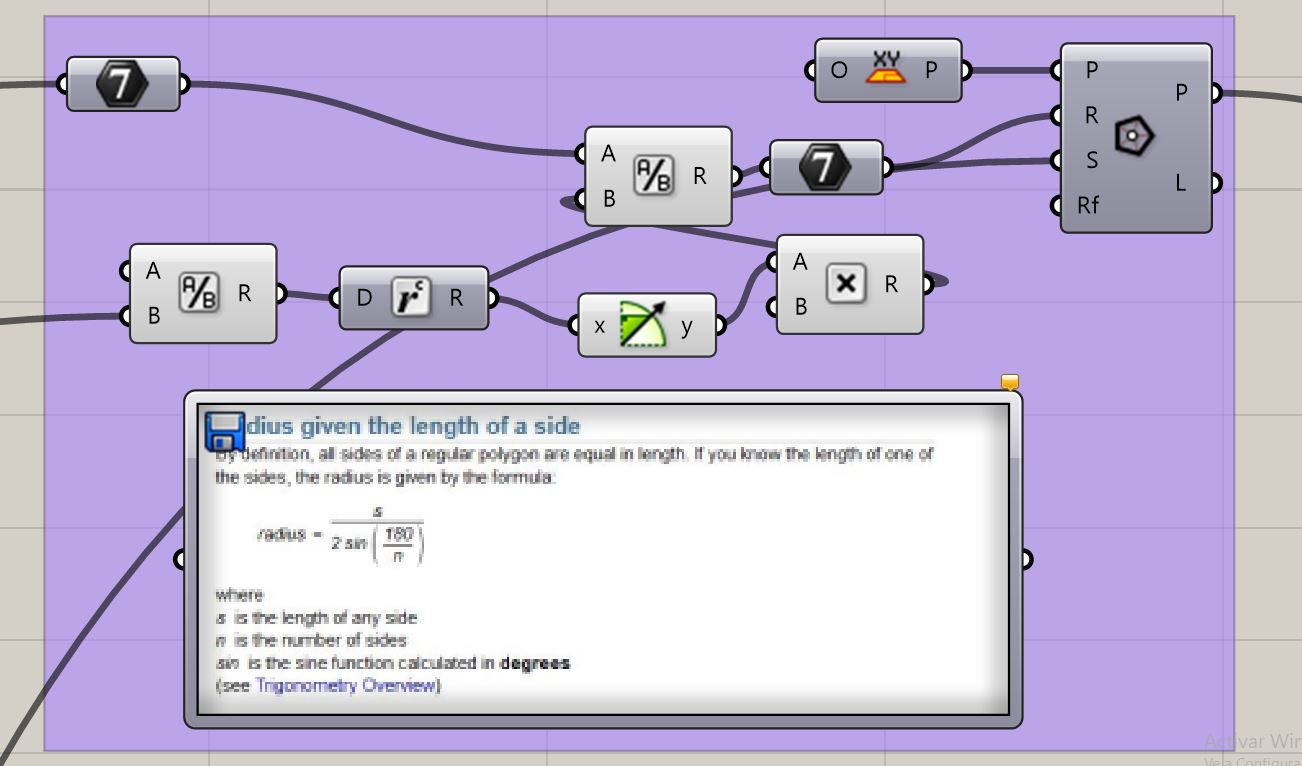
Because I had to make the radius and I didn’t remember the formula I added to the file as a graphic so I can know what the grasshopper is trying to mimic.
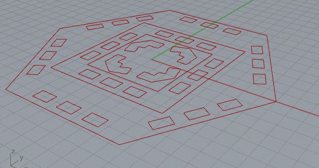
So first I made the faces and tested them. They were too small so thanks to grasshpper I could make the design bigger in no time.
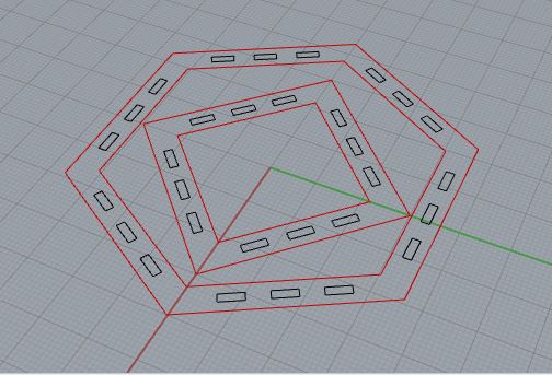
grasshopper design
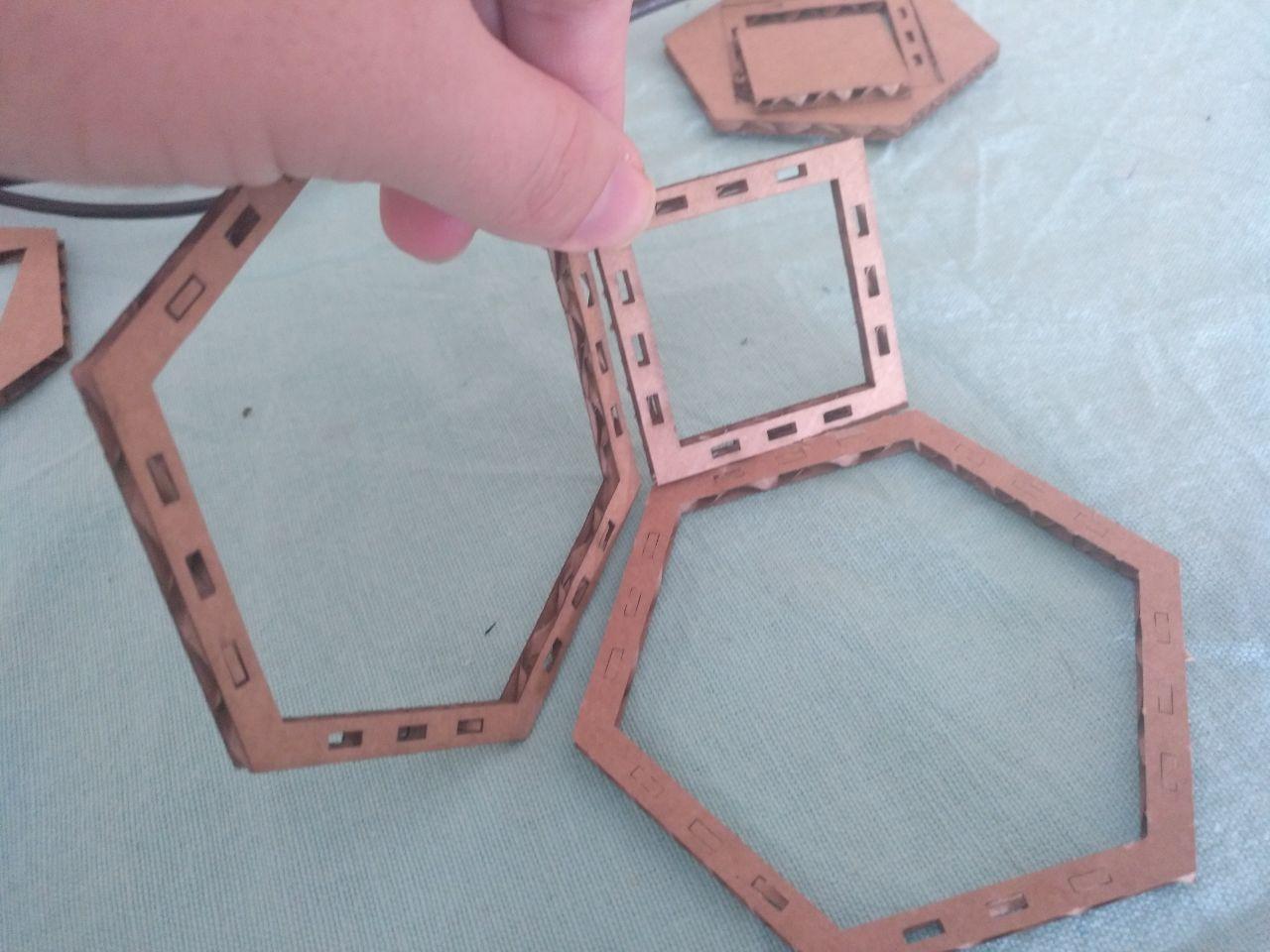 first cutted prototipe
It was too small and too thin and it wasted space in between pieces. It also helped me to adjust the power and the speed of the laser. (small trotec, 4mm cardboard, 40 power, 1 speed, 1000 Hz frecuency)
Laser machine used: * Trotec Speedy 100 (small one)
Parameters used: * 40 /100 power * 1 / 100 speed * 1 000 Hz frecuency.
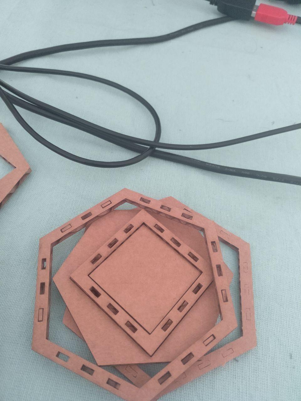 here you can see the wasted material
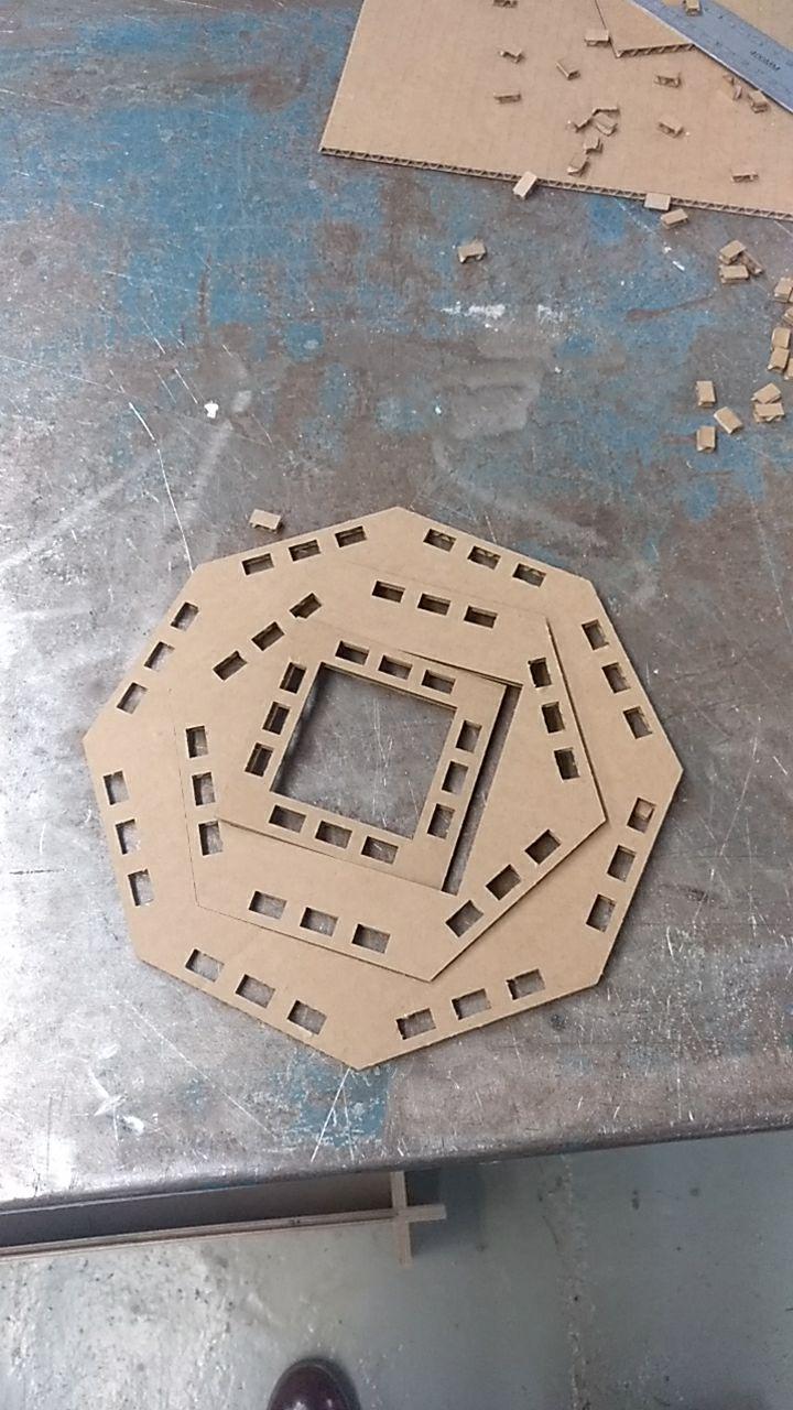
I also tweaked the design a bit to put the squares and the hexagons one inside another. And I added the Octagon just for fun and testing other sizes. (Octagon can be used also with combination of triangles and make somethink like this)
To do the hexagon and the square I just had to set a new parameters from the others. So that’s why I have 3 big blocks on the Grasshopper
So I cutted
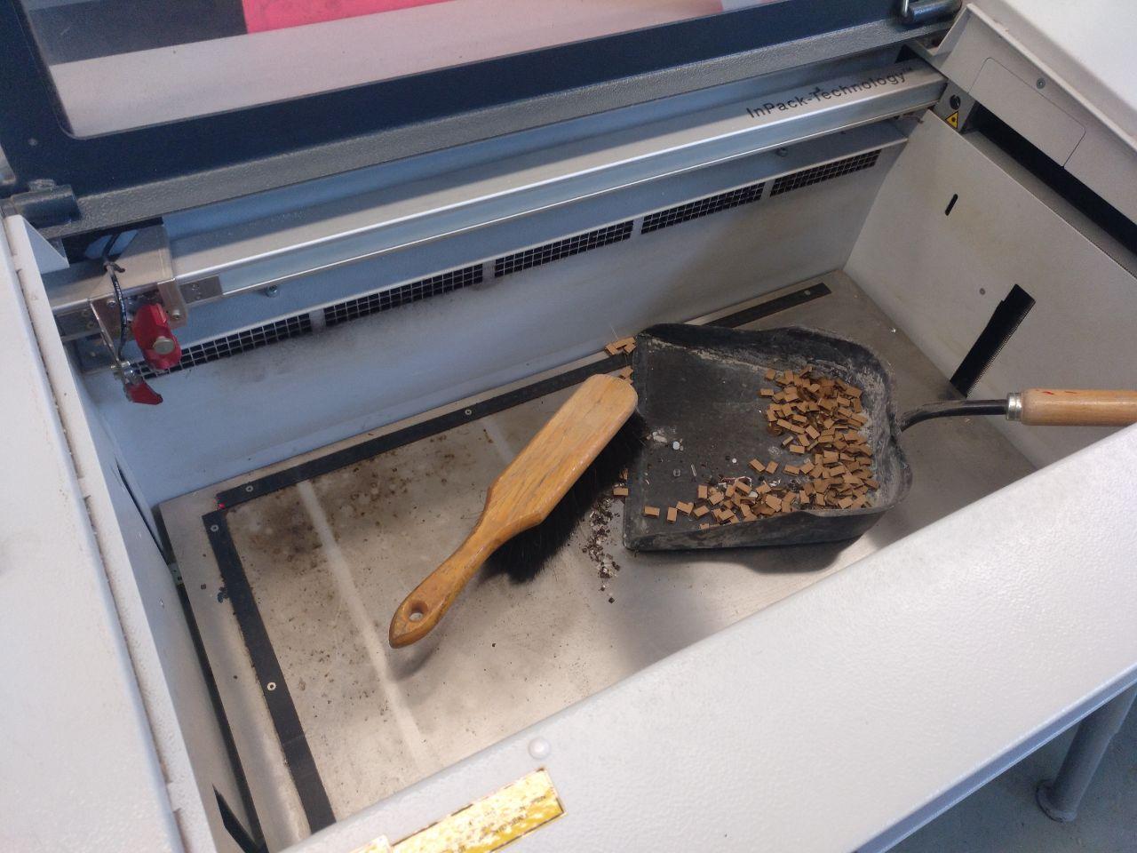
After I cut the pieces and I was happy with them, I noticed there were a lot of little holes of waste that I don’t want to be burned by the laser, so I cleaned it by taking out the bed.
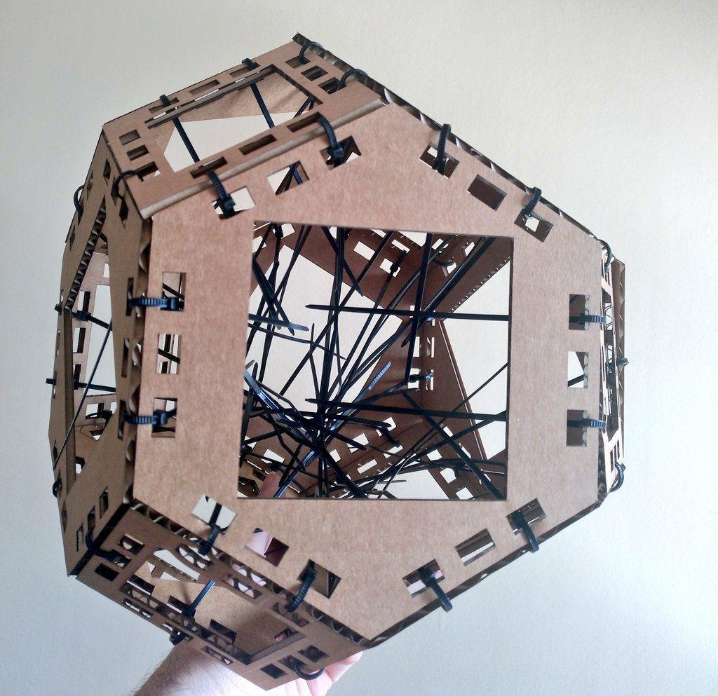
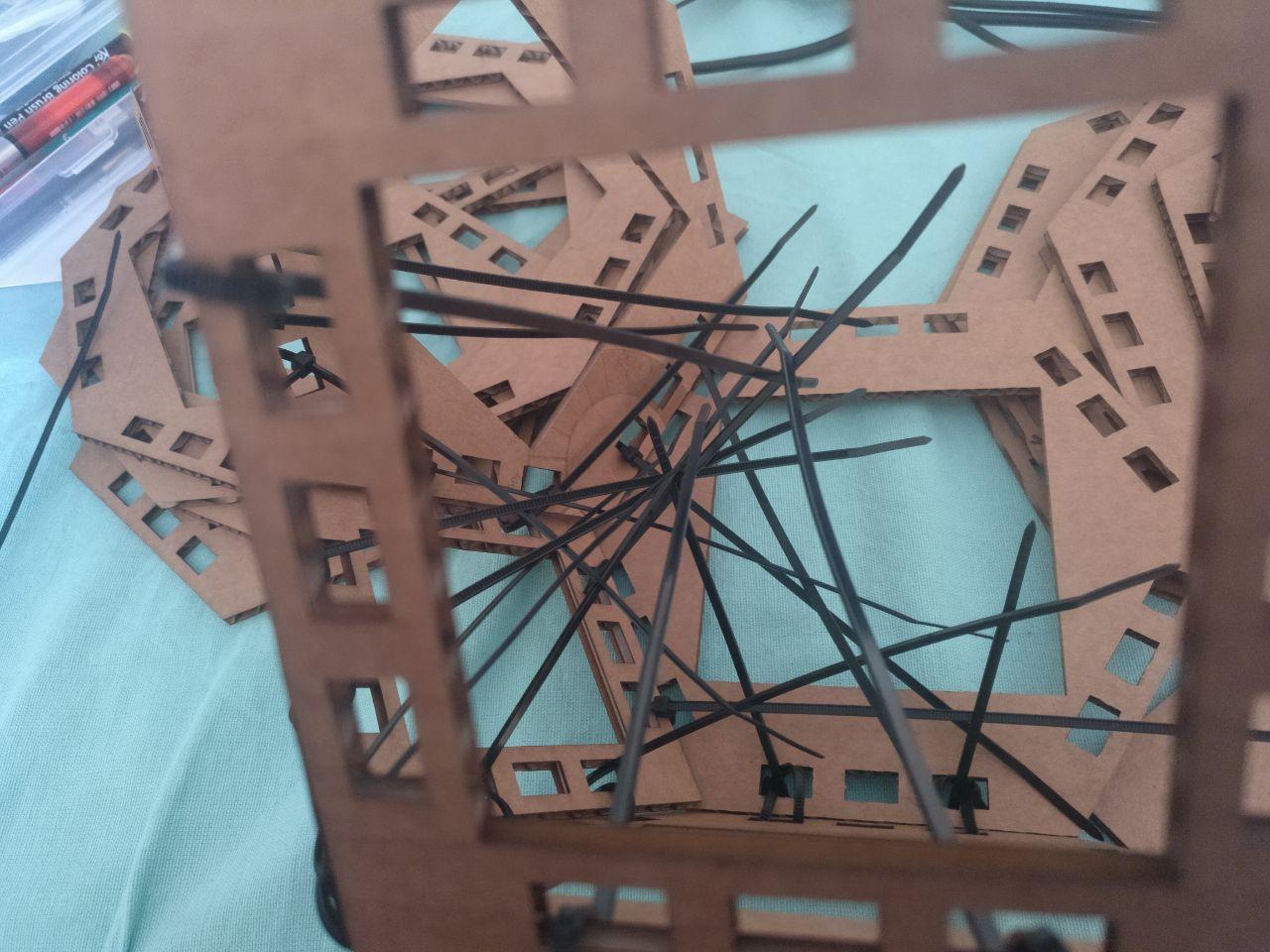
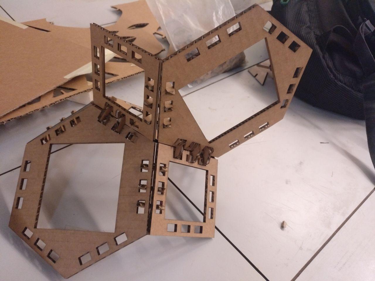
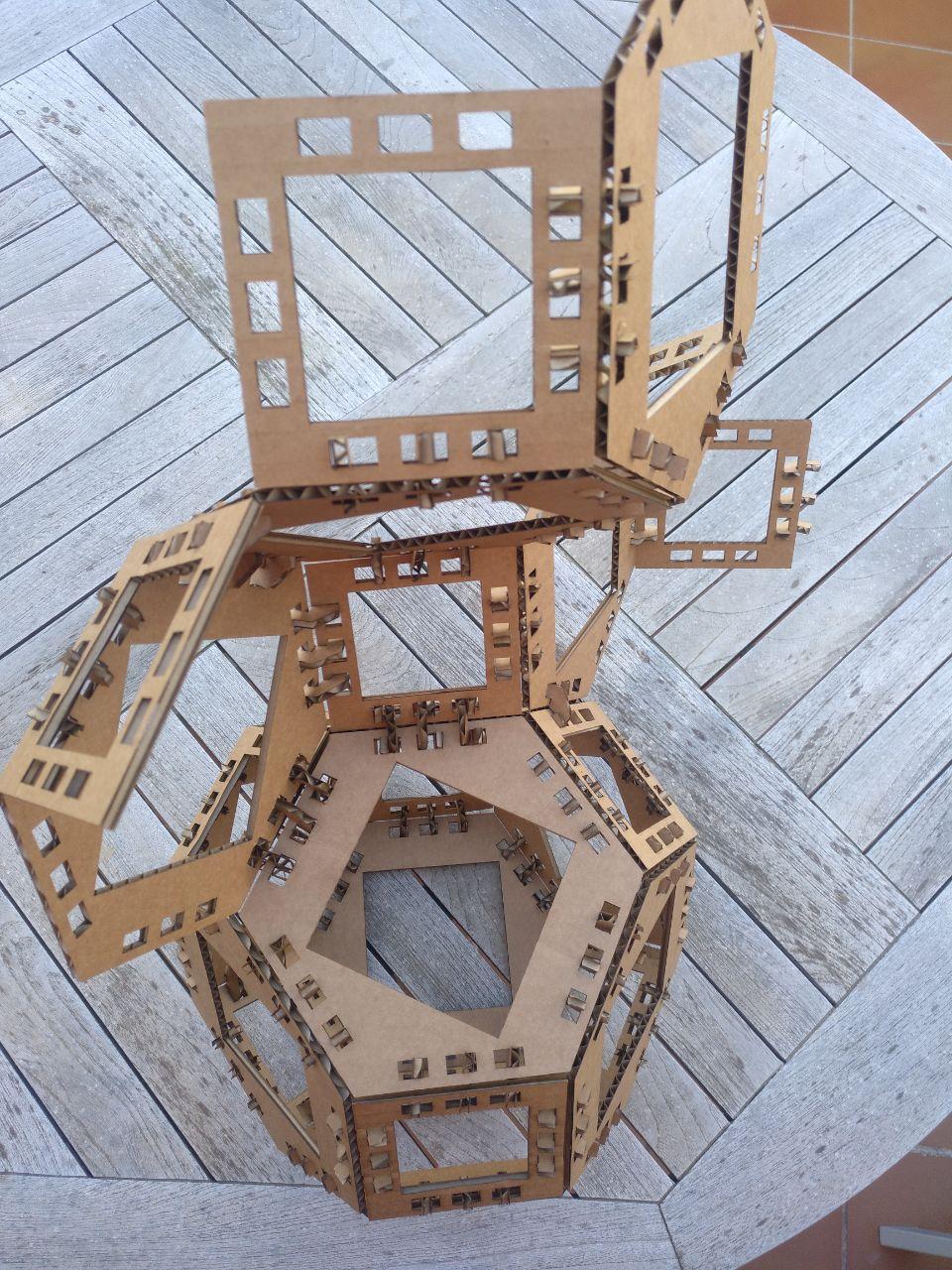
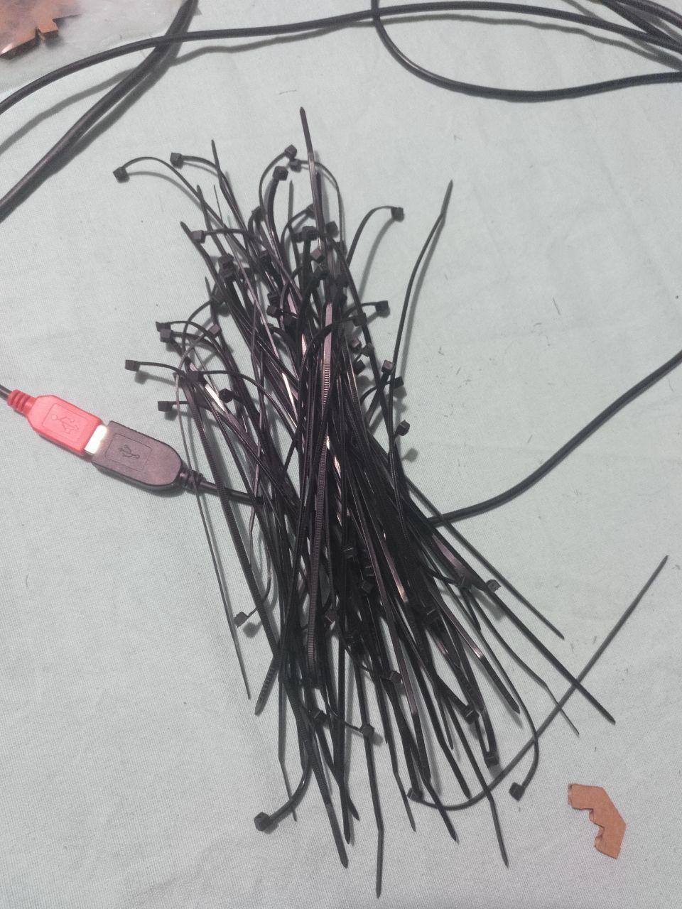
I could cut all the faces of the poliedron and make a couple more. The weekend I assembled the pieces with plastic stripes (in a way so I could reuse the stripes since I don’t like to make waste).
Assemble complete!
 Extra sides for you!
Designing the joint
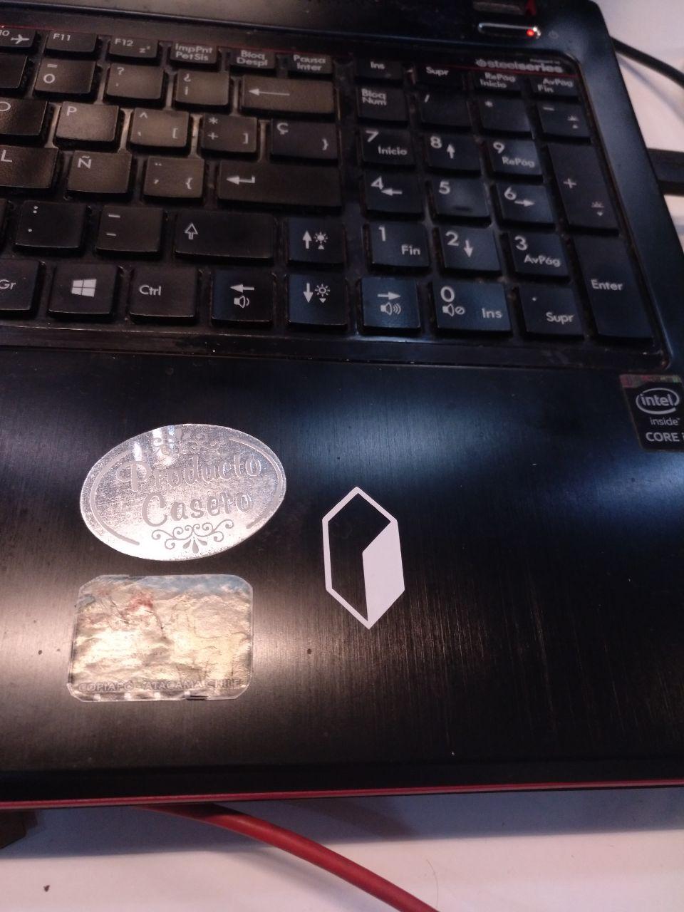
This was a bit tricky for me since in Grasshpper I had to make the dots be moved and arrange so I could make the polyline. I added a click with a arrow shape to fit better 2 of the sides and now one of the parameters was the angle between the faces that was a constant of 120 degrees. It was easy to confirm that after I mounted the first prototipe with the stripes.
In this case I was ignoring the kerf in porpuse because I was using cardboard and I’m relying on the flexibility of the cardboard and hopped that the arrow was enough to fit properly.
After a first test that fitted Hurray!
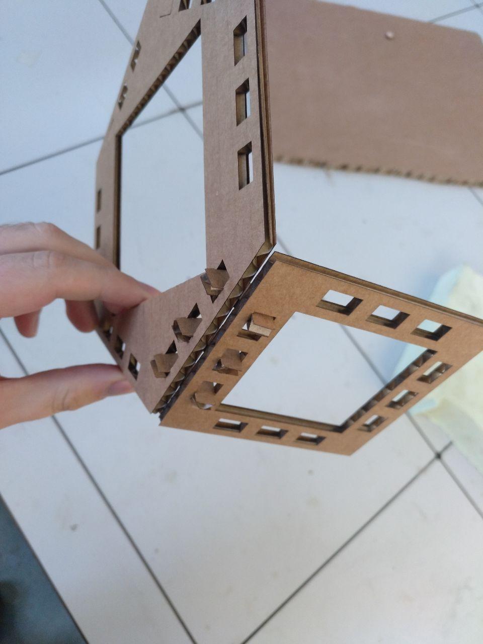
yaaaaay
I made another test to see how it works with more angles and also cut a couple of faces more. (Now without octagons)
Now I counted that I needed 108 joints in total for the poliedron. So I installed Deepnest.io and, boy that was amazingly useful to make 100 copies fittet properly.
Nesting it’s so cool they can make from this:
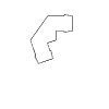
To this:
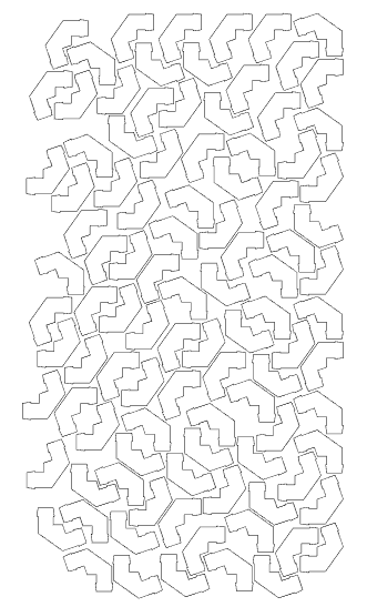 nesting automatically is cool!
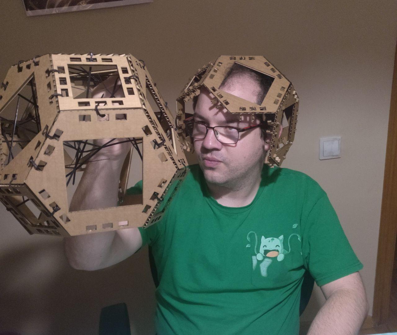
So I cutted them and some more faces and I mounted them at home ant I have my space tesellation.
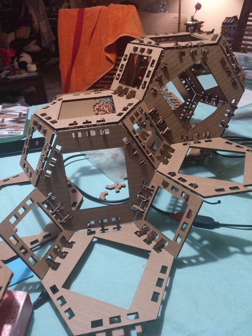 descriptive image
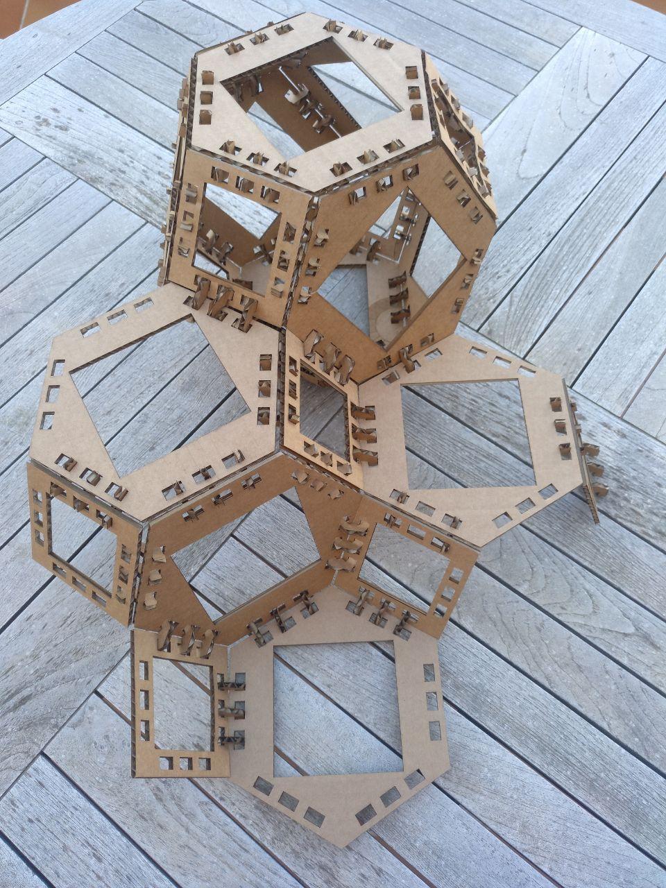 descritpive image
Here the plastic stripes that can be used once again.
Problems
-
One thing I couldn’t figure out it’s how are the points of the holes situated that was depending of the offset so with the different number of sides it was a little different. In this case was close enough but it need to be tweaked for extarpolate for other polygons so the holes are properly situated.
-
Cardboard can resist a couple of fits but it’s easily degraded.
-
The joints are fragile. They work fine together but when you mount and desmount the joints start to degrade at the third time you use them.
-
The design it’s not properly parametrized to change properly the angle of the joint (I used a mirror tool so it has to be tinkered)
Useful links
What I’ve learnt
-
Kerf it’s important when you have precision but you can dodge it with specific materials.
-
Grasshopper it’s long to do things but it’s rewarding and since it’s code it’s more reusable than drawings.
-
Deepnest.io it’s as amazing as they say. And the image they make it’s sometimes beautiful for other meanings.
-
Cardboard is an anisotropic material, specially in small pieces like the joints.
Possible outcomes
- Make other joints with other angles (90 degrees, 60, 135 degrees)
Design files
Remember to use download link as.. to download the files.
Me thinking of space tesellation: