11. Input devices
This week I’m going to try to start easy with a water/moist sensor and from that I’ll be building on. Maybe treat the data with firefly or process the signal with several types of convolution, which is a thing that Oscar told us yesterday and I want to invesitgate. I maybe also try to figure out if I can make and calibrate a capacitor sensor.
I’ll also try to design something easy as a board with an input in kicad. I’ll modify it
But let’s start with the simple things.
The moist sensor
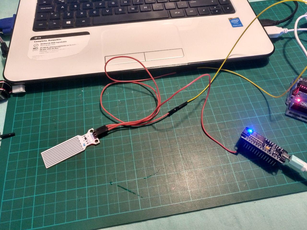
I have with me an input and output kit that the last day the fablab was open was given to me. In that kit there is a water sensor for arduino. This one:
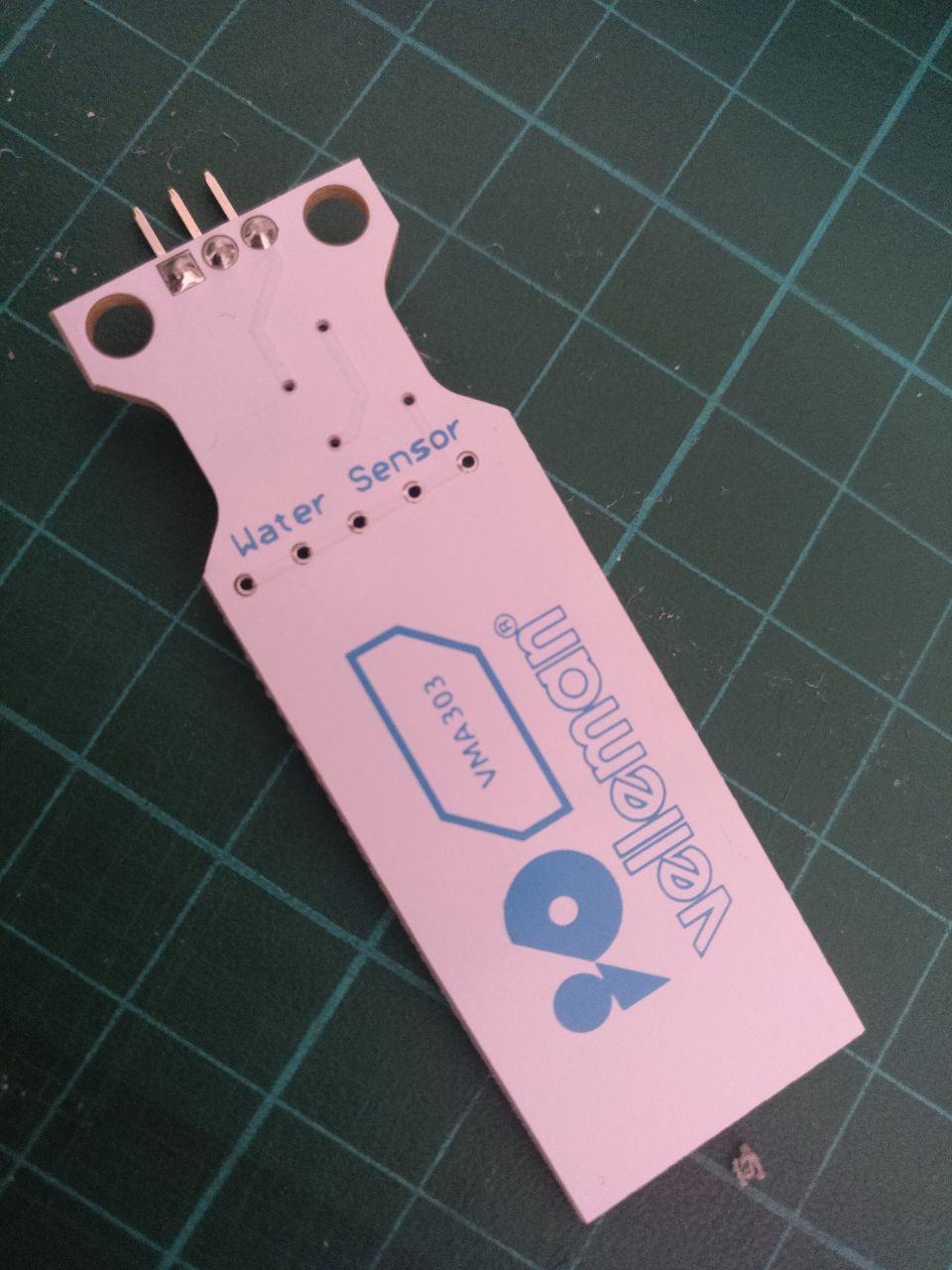
this is from one side
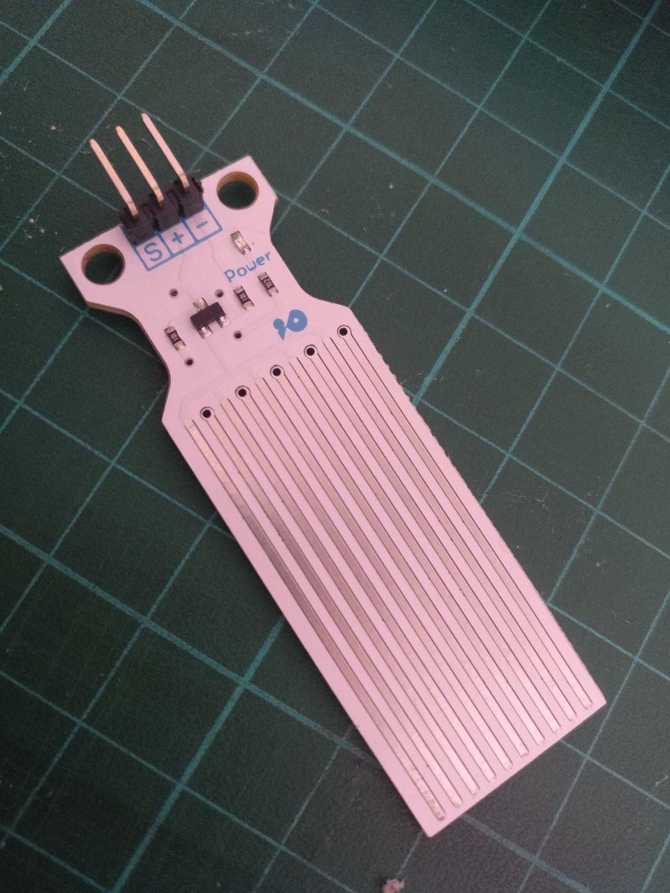
and this is how this sweet child looks from the other angle. Always looking for the camera attention. Naughty board.
The board has the user manual online but not the schematic. I figure out the schematic looking at the board but I’ll have to ask the instructors what it’s in the middle because the transistors are difficult for me to recognize and understand.
This is what I’ve figure it out.
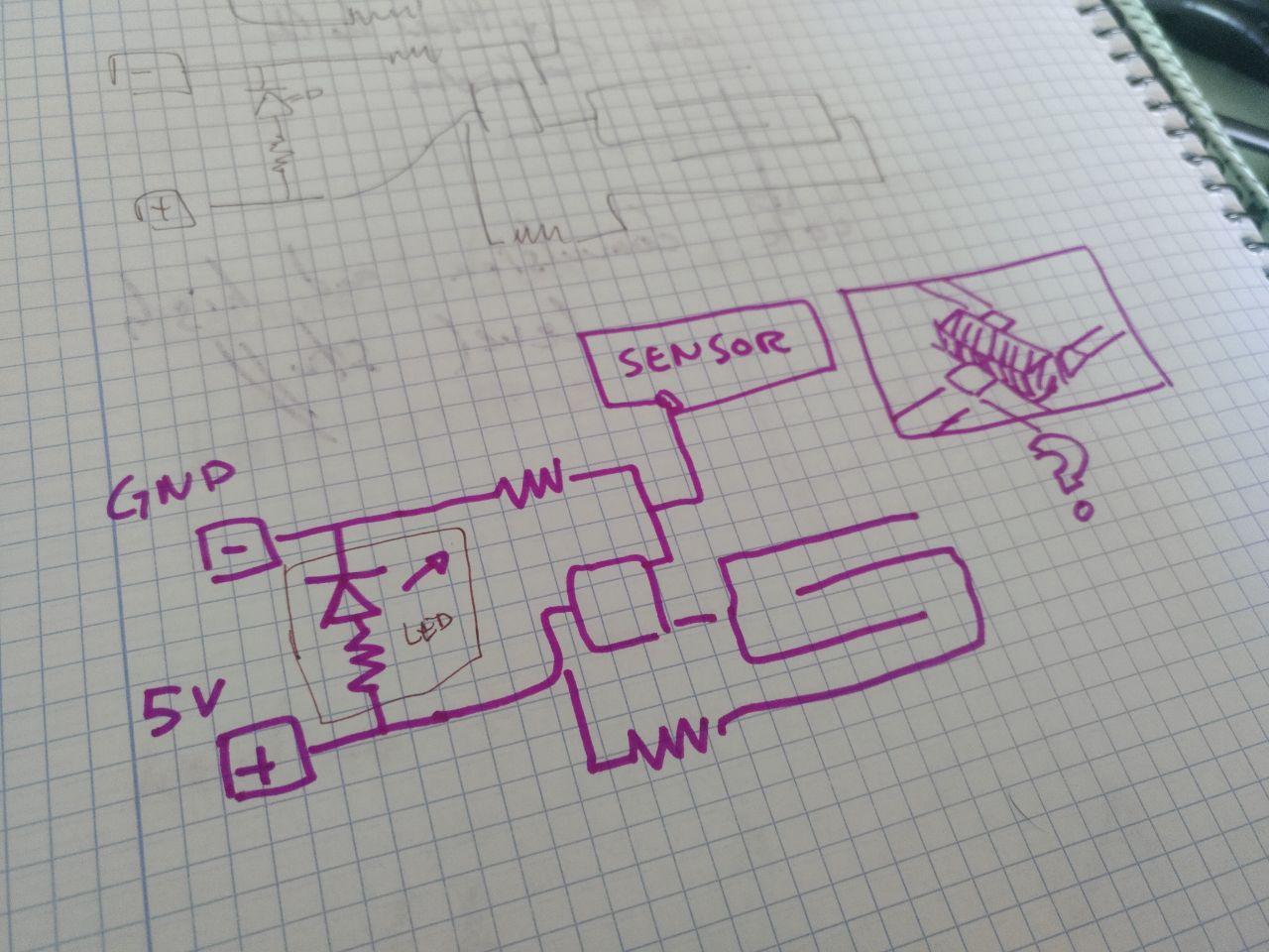
Marker schematics with an interrogation in the part that I cannot distinguish properly. It will be useful when I design the other board
The datasheet doesn’t say much about this particular sensor (you can find it here) but it seems that works in 5 volts.
I connected to the arduino that has 5 volts (Even if I cannot program it I can use it as a powersource).
Now I have to check where I can plug the sensor pin and how to read it and put it in the serial.
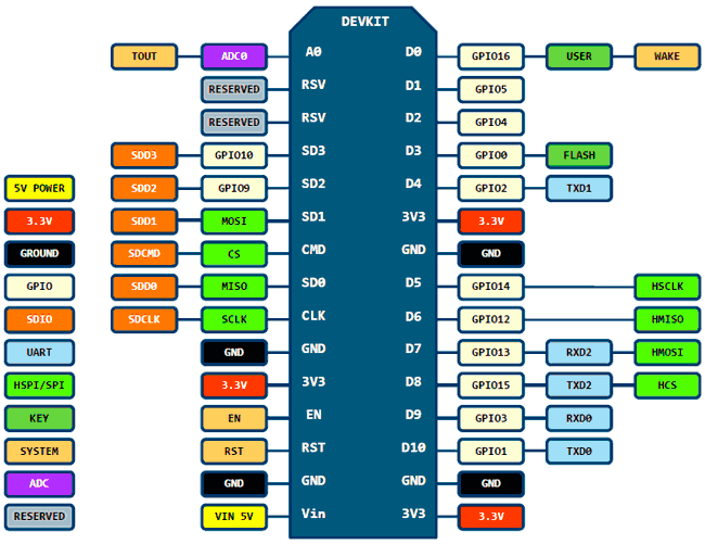
The NodeMCU says that the pin name is A0
you can see it in the eschematic that the only analog to digital it’s up on the left corner.
The premade example doesn’t seem to work, the readings are always low.
that was because I wasn’t connecting the sensor to the right pin with the jumper. After I plug it properly, it looks like this!
 For me it was very helpful to distinguish the power -dumb- source from the intelligent sensor but I don’t know if it works for anybody else
it works and I can read some values!
Yay!
weeek11/tears of joy.mp4
I modified the code to make a delay of 50 ms instead of 2 ms.The code is this one:
// These constants won't change. They're used to give names to the pins used:
const int analogInPin = A0;  // Analog input pin that the potentiometer is attached to
const int analogOutPin = LED_BUILTIN; // Analog output pin that the LED is attached to

int sensorValue = 0;        // value read from the pot
int outputValue = 0;        // value output to the PWM (analog out)

void setup() {
  // initialize serial communications at 9600 bps:
  Serial.begin(9600);
}

void loop() {
  // read the analog in value:
  sensorValue = analogRead(analogInPin);
  // map it to the range of the analog out:
  outputValue = map(sensorValue, 0, 1023, 0, 255);
  // change the analog out value:
  analogWrite(analogOutPin, outputValue);

  // print the results to the Serial Monitor:
  Serial.print("sensor = ");
  Serial.print(sensorValue);
  Serial.print("\t output = ");
  Serial.println(outputValue);

  // wait 50 milliseconds before the next loop for the analog-to-digital
  // converter to settle after the last reading:
  delay(50); //changed
}
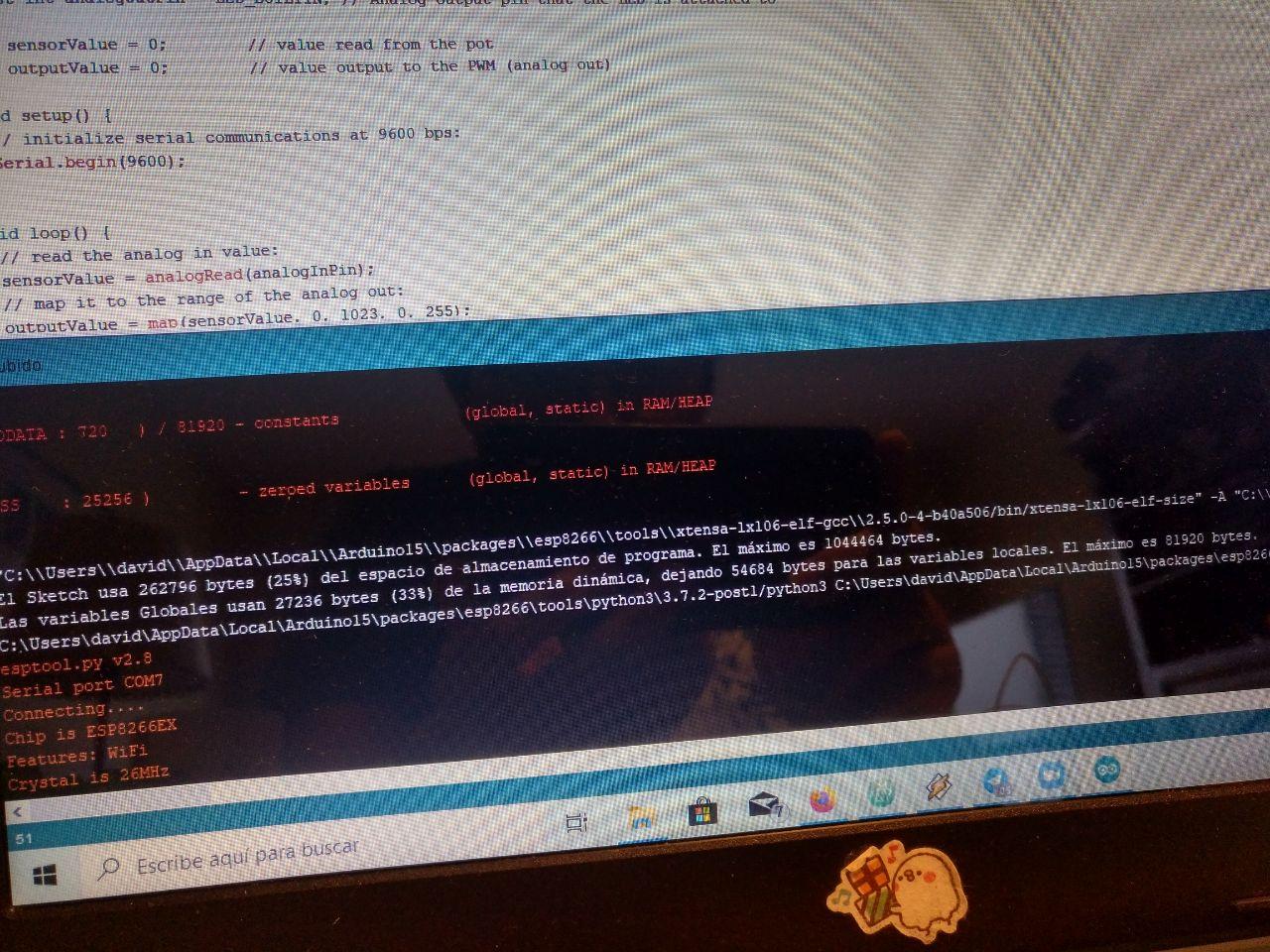 when I uploaded it takes a 25% of the board capacity
I noticed that the code works to measure values from 1 to 1024 if they work at 5v. If you work with 3v3 (that would be what this nodeMCU has but the arduino can power 5v) you only get up to “400” or “500” as a maximum.
The moist sensor 2: Moister than you.
To continue to investigate how these inputs works I go back here and I’m going to upload an easy sketch into a barduino using platform.io.
The idea it’s to traspass the program I have for the NodeMCU and work from there.
I did it for the networking week when I used the moist sensor in the hyperconnected session.
More updates. Several buttons for the Final Project (Monolith)
For the final project I needed a human input of button-like. I tested capacitive but they didn’t work because the micorcontroller has touch pins but they are calibrated to… literally touch and the Monolith in design it’s not metallic and I couldn’t get through 4 mm of carboard. So I went for some traditional switches. For each face I had a pulled up pin that, if the face was touched, they went to ground. It’s not super-duper high technology but it’s still a useful digital signal.
If you want to see the development of the hardware (how it’s wired) you can see it here and the programing you can see it here
The hardware part is specially extensive so you may want to see in order:
-The mounting of the first final face
Shock input for an Attiny 1614
I’m going to try to use a shock sensor. Luckily there is some documentation to start with from the instructors. That would be cool for the Monolith. I’m going to put it in a board with an Attiny1614. So let’s figure how to make it work
Analysis of what the board needs.
Ok, looking at the board we need the connection with a ground with a resistor and a pin. And another pin for the LED signal. (it’s technically an output but it’s useful so I can debug it separately)
Here in the week of electronic design I’m going to talk about the board.
Programming the sound sensor
I tried the code that is in the Barcelona lab page modifying it a little bit to be in the right pins.
int shockMin = 996;  //you might need to change these
int shockMax = 1010;  //you might need to change these

void setup() {
  pinMode(A1, OUTPUT);
  Serial.begin(9600); //uncomment this to help with calibration
}

void loop() {
  int shock = analogRead(A2);
  int lightval = map(shock, shockMin, shockMax, 0, 255);
  if (lightval > 0) {
    analogWrite(A1, lightval);
  }
  else {
    analogWrite(A1, 0);
  }
   Serial.println(shock); //uncomment this to help with calibration
}
Not very fancy but it should work.
It doesn’t work. If I put the cables together the LED blink but if not it doesn’t and maybe it’s because calibration but when I open the serial com in the arduino Ide, it doesn’t work. So let’s try a more simple program just to test the serial communication. I will use this echo here
Using 112500 bauds doesn’t work even if the led blinks. Maybe I have to use a small baudrate. Let’s try 9600
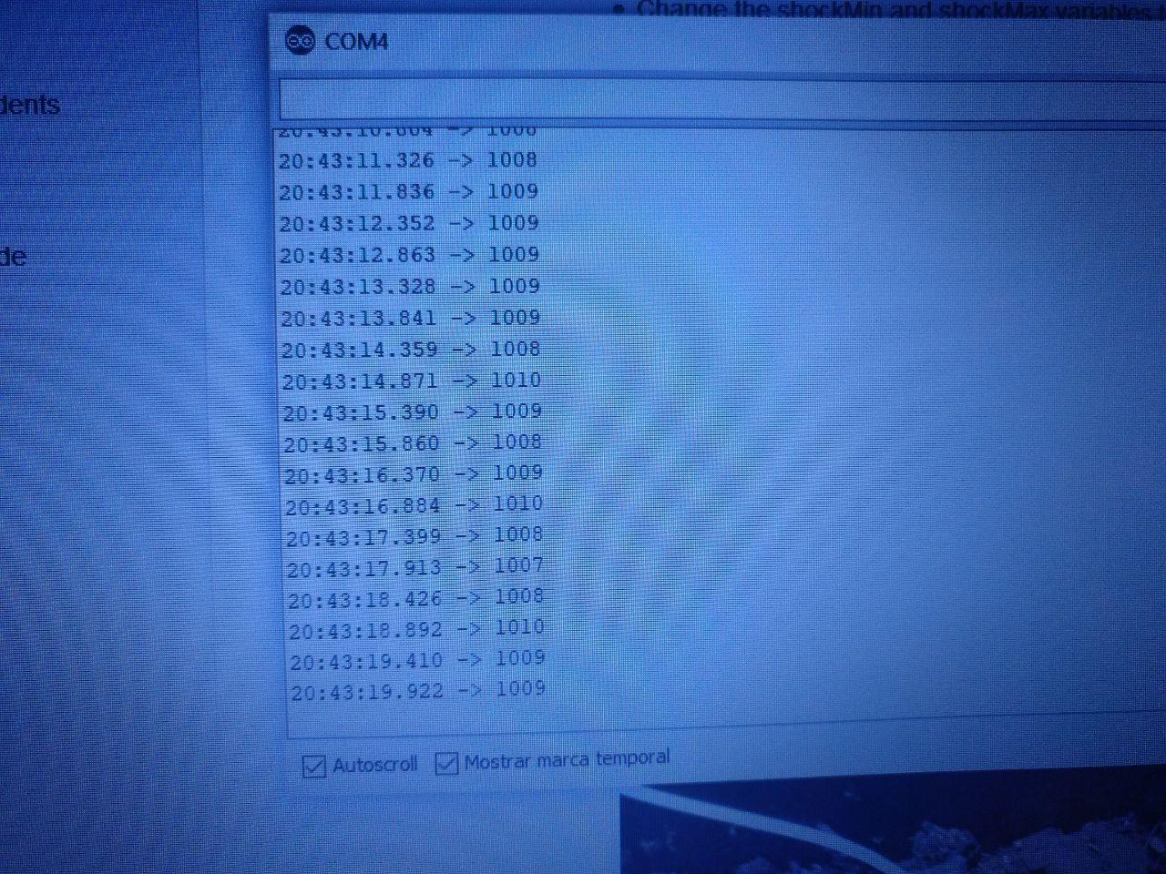
What I have realized is that I have a failure in the design of the PCB. It seems that the RX and TX are mixed and that’s the reason I don’t receive data. The problem is that even with I solve it with jumpers the micorcontroller doesn’t recieve data properly from the computer. But at least it seems that it can send information. That’s something.
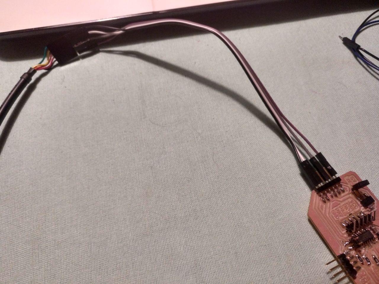
le hack
When I received signal the values were too static (1007-1009), maybe because 500 ohms it’s too high as a resistor and it may be should be 100 ohms.
I can use the snapshot tool but sometimes take this kind of pictures is fancy
I tried another speaker I had and I had the same problem…
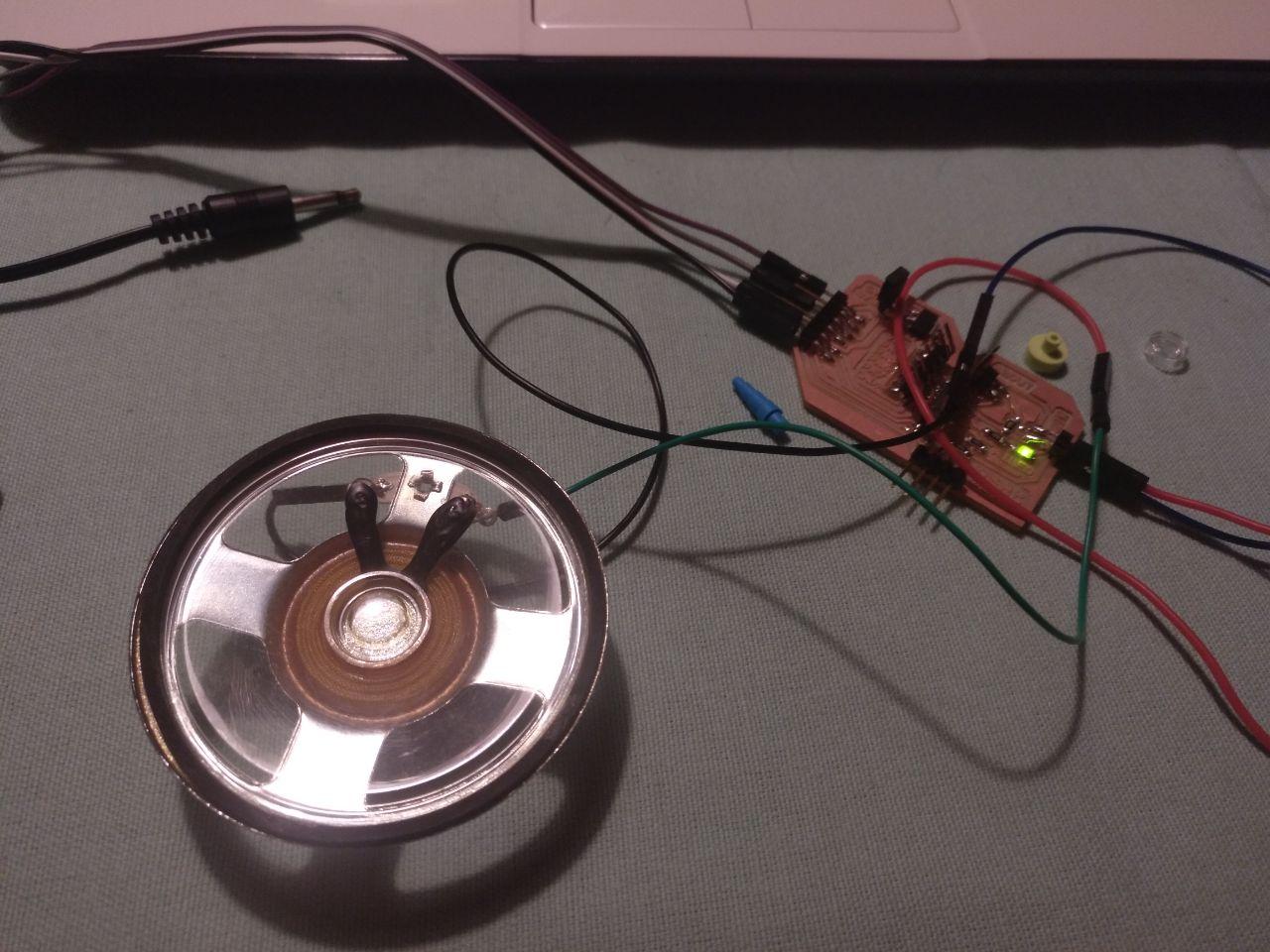
speaker!
until I yelled at the poor speaker.
Then it worked. I have a sound sensor that is hard on the ear. Fantastic. At least it works.
Hero shot
Code used
This is the code:
int shockMin = 1001;  //you might need to change these
int shockMax = 1020;  //you might need to change these

void setup() {
  pinMode(A1, OUTPUT);
  Serial.begin(9600); //uncomment this to help with calibration
  Serial.print("Hi, starting connection");
  Serial.print("/n");
}

void loop() {
  int shock = analogRead(A2);
  int lightval = map(shock, shockMin, shockMax, 0, 255);
  if (lightval > 0) {
    analogWrite(A1, lightval);
  }
  else {
    analogWrite(A1, 0);
  }
   Serial.println(shock); //uncomment this to help with calibration
   delay(500);
}