12. Output devices
This week I’m planning to do these Things
-
Make the servo motor we have from the arduino set work with a barduino.
-
Try to measure the power consumption of the servo.
-
Connect the moist sensor and make the sensor change if the servo works or not.
-
Try to make a diy output.
-
Try to use and old radio with the speaker to do something.
-
Design something looking to advance something for the final project.
The little arduino servo
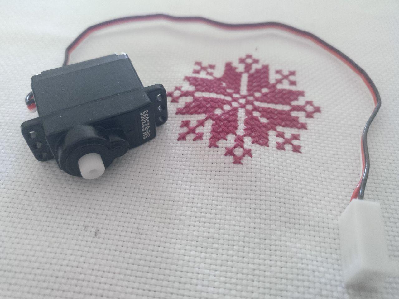 this is my little servo motor, there are lots of them but this one I can use it
The servo I have it’s this one. sm-s2309s. Luckily it has a sticker with they name son it was easy to find.
The datasheet doesn’t say a lot but here it is.
Now I have to figure out which are the pins that they need. I’m going to use the ESP32 barduino 2.0 that we have. Here is the project to check it out
 Now I undertand that PWM means that I can module the signal using pulses
Now, thanks to the class I understand better more of the pin coding that the board has.
In this case, the servo has an internal controller so I only need a VCC pin, a Ground pin and a signal pin.
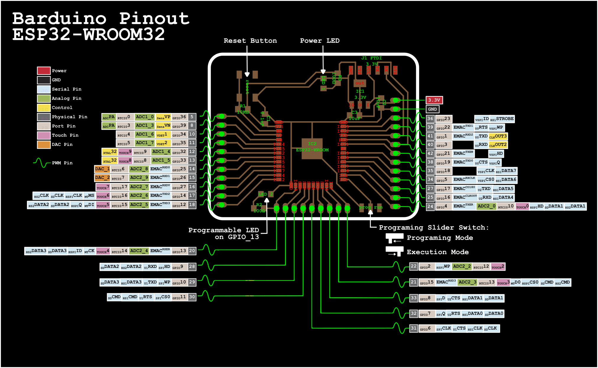 Down to the right it’s the pin 24
I choose the pin 24. And just to be sure (and avoid further errors if I make a mistake) I test it by using the simple led circuit.
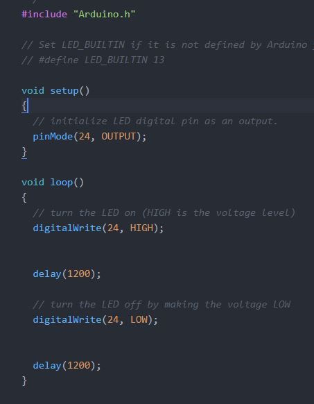 I just put the screenshot because it’s the blink sketch but in the pin 24
The sketch doesn’t work so we start well. I tried to just put a resistor and look for any voltage with the multimeter but I don’t see the blink.
So I change the code to blink the 24 and the 13 pin (because it’s the built in led) just to check if the board is fine (because I still have problems with the connection to the pc)
I think it was a good idea because I got confused and I missnumbered the pins (again), luckily I could end by making another pin blink, so cool.
little blink in the other pin (title of your sextape)
Now let’s try the servo just like that.
Doesn’t work. I guess that it takes the signal to rotate to the limit and once it’s there it stays like that.
Now let’s try the arduino library of servo and the example. It shouldn’t be that hard to make it work.
Going to the reference of arduino of servomotor, I find thte sweep tutorial
I tried it and modify it a little so I still use the internal led so I have a way to know that it’s working. In this case, when it’s turning in one side it lights and when it’s in the other side, it fades out. Easy.
#include <Servo.h>

Servo myservo;  // create servo object to control a servo
// twelve servo objects can be created on most boards

int pos = 0;    // variable to store the servo position

void setup() {
 myservo.attach(25);  // attaches the servo on pin 25 to the servo object
 pinMode(13, OUTPUT); //led builtin on barduino 2.0
}

void loop() {
 for (pos = 0; pos <= 180; pos += 1) { // goes from 0 degrees to 180 degrees
   // in steps of 1 degree
   myservo.write(pos);              // tell servo to go to position in variable 'pos'
   delay(15);                       // waits 15ms for the servo to reach the position
 }
 digitalWrite(13, HIGH);
 for (pos = 180; pos >= 0; pos -= 1) { // goes from 180 degrees to 0 degrees
   myservo.write(pos);              // tell servo to go to position in variable 'pos'
   delay(15);                       // waits 15ms for the servo to reach the position
 }
 digitalWrite(13, LOW);
}
Before I upload the code (I still have problems with uploading the code but I believe that there is a problem with the cable that’s unstable rather than the board) I compile it and I found that there were 2 problems.
The first one is that the library servo it’s not installed. To install it in platform.io the cli gives you the option to search for it. I type: platformio lib search “header:Servo.h”
And the answer is several libraries that fit that description. I installed this one:
ServoESP32
==========
#ID: 1739
Generate RC servo signal on a selected pins with ESP32 device and Arduino framework.

Keywords: esp32, servo
Compatible frameworks: Arduino
Compatible platforms: Espressif 32
Authors: Jaroslav Paral
Since barduino it’s a ESP32 and it seems general, I installed it using this command (achiavable by the help command also)
PS C:\Fabacademy\Electónica\platformio\platformio barduino\Startbarduino2.0> pio lib install 1739
Library Storage: C:\Fabacademy\Electónica\platformio\platformio barduino\Startbarduino2.0\.pio\libdeps\esp32dev
LibraryManager: Installing id=1739
Downloading...
Unpacking...
ServoESP32 @ 1.0.2 has been successfully installed!
To check if I’m not installing something wrong (Because I used the id of the library instead of the name because all the libraries seemed to be called SERVO) I wrote the command to check it out.
PS C:\Fabacademy\Electónica\platformio\platformio barduino\Startbarduino2.0> pio lib show 1739
There I find that I can use the servo.h that the code I pasted uses.
Headers
-------
Servo.h

Examples
--------
http://dl.platformio.org/libraries/examples/17/1739/01-SimpleServo.ino
http://dl.platformio.org/libraries/examples/17/1739/02-ServoPotentiometer.ino
http://dl.platformio.org/libraries/examples/17/1739/03-MultipleServos.ino
http://dl.platformio.org/libraries/examples/17/1739/04-SimpleServoAngles.ino
Once I done it again there is an error and it’s that if you have several files .cpp the engine it’s going to compile all of them so if you happen to have several loops and setups it’s going to say “tururú” if you want to compile. I had the anterior sketch so what I did it’s to create another folder to store the drafts sketches I’m not going to upload.
And when I upload it to the board:
yay it’s alive and it goes and it comes back
Oh, and I had to connect the in and out of the motor to a 5v exit of an arduino to have power enough. If I have to design something now I have to take that into acount (that if use a power source I need 2 voltages at least, 3v3 for the ESP32 and 5v for the motor). This is hte map:
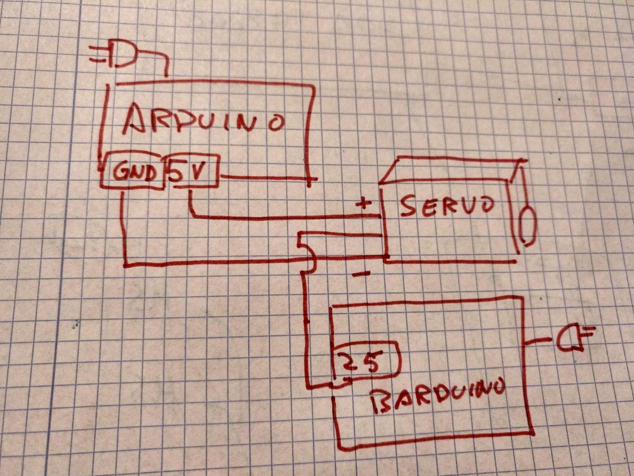 sometimes it’s easier to make a drawing and upload it than try to make a accurate digital schema
Measure the power consumtpion of the little motor
As the group assigment we have to compare the power consumption of our devices. I have a little motor that it’s not fighting any force (because I don’t have gears that fit that motor, yet) so it should be little.
To do so, I have to put the multimeter in the middle of the wiring when it’s up. In this case I have a multimeter that measures up to 10 A. And the motor starts and stops so the power consumption is variable. Let’s get to the top.
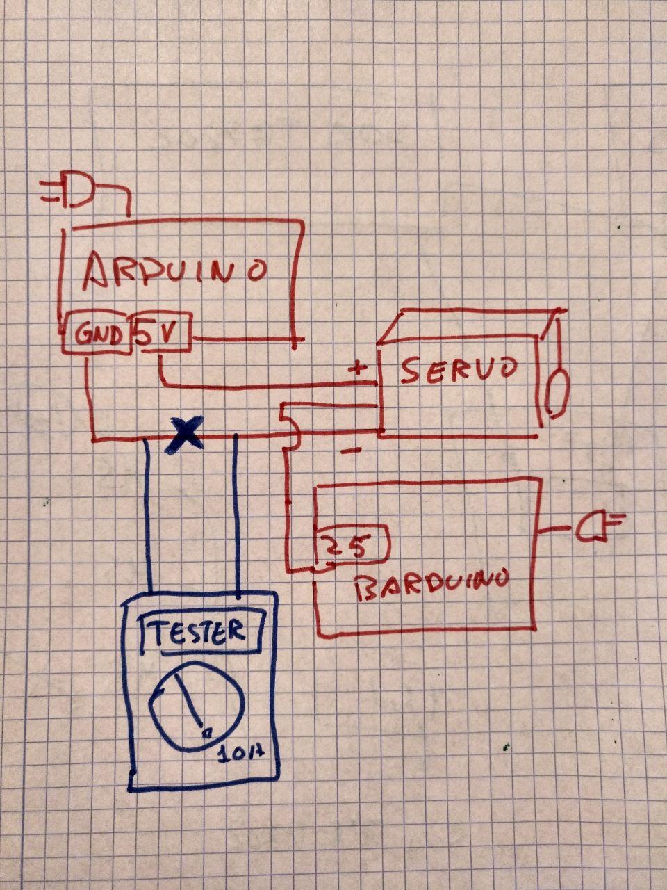 Schema of how to connect the multimeter. It’s important to disconnect the current so it goes through the multimeter
To do so I divide the circuit and I add a breadbord so I can conect without hustle the multimeter like This
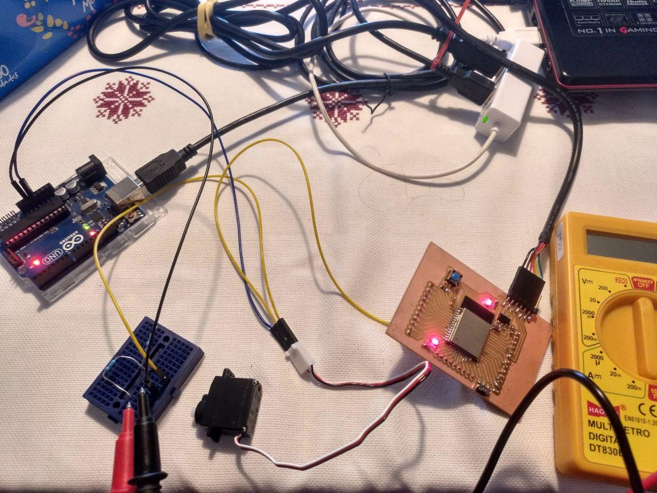 messy breadboards are messy
~~And this is the result, through several readings (non recorded) the value varies and it goes up to a top of 3.8 A and then goes back when it turns.~~
~~So with a voltage of 5 V and a 3.8 A, the power on top it’s 19 W (because power equals current times voltage). As if it varies within time, it could be estimated on half that power (9.5W) in terms of how much electricity consumes over time, but it would be necessary to measure the curve of the current more carefully.~~
But that’s wrong.
The day after, helping Tue with the multimeter I found that I was measuring it wrong. There is a differnt pin for measuiring the current.
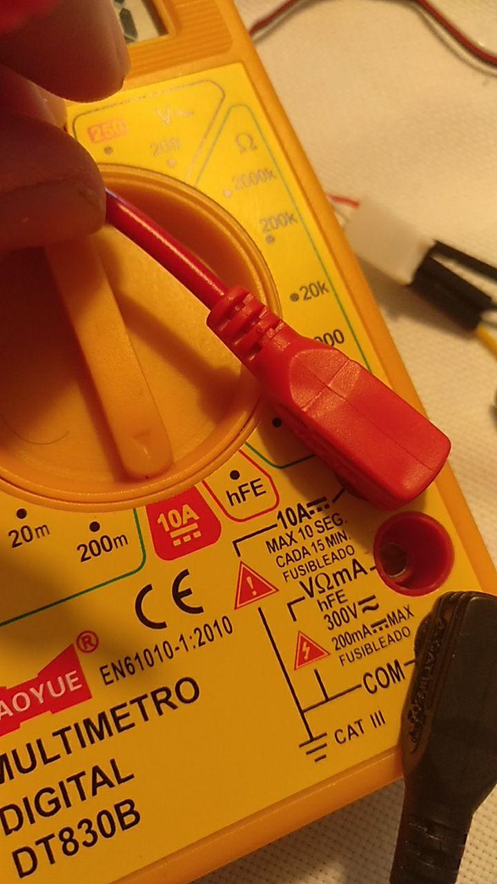 remember to double check your multimeter, kids
If I connected that way the measurings are more stable and, I guess that correct. The servo is sweeping and when it turns it goes to 200 mA and when it’s steady it’s 150 mA. So with a voltage of 5 V and a 0.2 A, the power on top it’s 1 W (because power equals current times voltage). And on stable it’s 0.75 W that it’s something more plausible.
Speaker time!
I come back to this week because I want to try to make some sounds with these codes because my project has sound! So I checked out the Roger Anguera week and I’m trying to follow his steps.
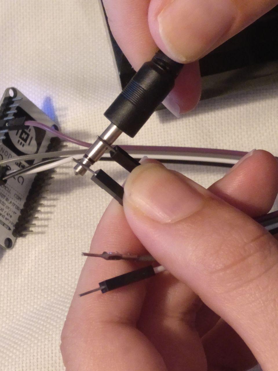
I do have a spare speaker from a radio that has a jack connector (that I guess it’s + - connection). I don’t know which it’s the positive and the negative.
Looking in the internet seems that the tip is the positive and the shield is ground. Let’s work that way

Image in French. I like the “hot point” thingy
Let’s try the easy way and try to connect one of the bands.
Then I’m going to try the sketch of Roger.
And it doesn’t compile. Because libraries I hate that. It seems that since I’m still using NodeMCU instead of the barduino (that it’s a ESP32) I have to use other code. Reaching a bit I stumbled upon this guide. Let’s try it.
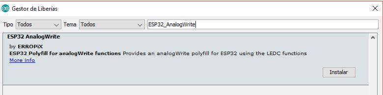 By the way I tried to instal this library. But I guess that only works on ESP32 boards, so let’s move on
The guide it’s about all pwm but as Roger stated, speaker it’s only a kind of PWM so it can use the same principle. Now that it at least compiles without complaining we can adapt Roger’s code.
The key part of the code of Roger is this little functions:
ledcSetup(ledChannel, freq, resolution);
ledcWrite(ledChannel, dutyCycle);
In the first it makes the setup with const int freq = 5000; const int resolution = 8; (I guess that’s in bits)
And ind the ledwrite goes from scales of 0 to 255.
This is going to end up noisy. But in the example I have this is what they use:
analogWrite()
Analog write uses a pin and a value that in the case of esp8266 comes from 0 to 1023 (8 bits)
But I still don’t get what is the resolution I’m working. From the base it seems that it works with a different range and frequency
You can change the PWM range by calling:
analogWriteRange(new_range);
By default, ESP8266 PWM frequency is 1kHz. You can change PWM frequency with:
analogWriteFreq(new_frequency);
So I guess that If set a value of 512 and frequency of 440Hz I could get a LA (A) sound.
But first let’s try with a led because I may mess up again with the pins or something and then we go with the speaker.
The code it’s this one:
const int ledPin = 2;

void setup() {

}

void loop() {
  // increase the LED brightness
  for(int dutyCycle = 0; dutyCycle < 1023; dutyCycle++){
    // changing the LED brightness with PWM
    analogWrite(ledPin, dutyCycle);
    delay(1);
  }

  // decrease the LED brightness
  for(int dutyCycle = 1023; dutyCycle > 0; dutyCycle--){
    // changing the LED brightness with PWM
    analogWrite(ledPin, dutyCycle);
    delay(1);
  }
}
As always pin2 means D4. Because pin layouts. At least I got it quickly. And here we have the result with the LED fading
And if I connect the mini-mono jack I got some sound but it was just a stable not changing sound. I tried to interchange the cables but it seems that it didn’t matter negative and positive.
This is how I plugged it.
So let’s try something like this:
We do have (thanks to Roger’s link) access to the chromatic scale frequencies so we can play a little bit with it. He made a random sing thingy but I’ll start with something to test if it modifies the frequency.
These are the frequencies:
int freqs[] = {261.63, 293.66, 329.63, 349.23, 392, 440, 493.88}
Writing in C++ when you are not used to because you use java or python makes you fail a lot in the compiling because of the ; that you have to put but you put only a ; but with a little of patience I get into this:
#include <Arduino.h>

const int ledPin = 2;
const int freqs[] = {261.63, 293.66, 329.63, 349.23, 392, 440, 493.88};

void setup() {

}

void loop() {
  for(int new_frequency_index ; new_frequency_index < 8; new_frequency_index++)
  {
    //write new frequency
    analogWriteFreq(new_frequency_index);
      // increase the power
      for(int dutyCycle = 200; dutyCycle < 400; dutyCycle++){
        // changing the power
        analogWrite(ledPin, dutyCycle);
        delay(50);
      }

      // decrease the power
      for(int dutyCycle = 1023; dutyCycle > 0; dutyCycle--){
        // changing the power
        analogWrite(ledPin, dutyCycle);
        delay(10);
      }
    }
    analogWrite(ledPin, 0);
    delay(1000);
}
Now it does sound but I don’t fully understand how. So for keep debugging and anderstanding the dutyCycles and the writes and the delays… I’m going to use serial debugging
To the BAT-SERIAL-DEBUGGATOR
noises of debugging
Uhm. When I tried this it didn’t work at all. And the serial doesn’t answer in the serial. That’s weird.
noises of fixing
When I analyze and correct the code (the new frequency index variable wasn’t correctly initialized and I was using the frecuency directly instead os using the array index.
Now it works.
const int ledPin = 2;
const int freqs[] = {261.63, 293.66, 329.63, 349.23, 392, 440, 493.88};

void setup() {
Serial.begin(115200);
Serial.println("Start setup");
}

void loop() {
  Serial.println("Start loop");
  for(int new_frequency_index = 0; new_frequency_index < 7; new_frequency_index++)
  {
    //write new frequency
    Serial.println("New Frequency");
    Serial.print(freqs[new_frequency_index]);
    analogWriteFreq(freqs[new_frequency_index]);
      // increase the power
      for(int dutyCycle = 200; dutyCycle < 400; dutyCycle++){
        // changing the power
        analogWrite(ledPin, dutyCycle);
        delay(50);
      }
    Serial.println("New Frequency");
      // decrease the power
      for(int dutyCycle = 1023; dutyCycle > 0; dutyCycle--){
        // changing the power
        analogWrite(ledPin, dutyCycle);
        delay(10);
      }
    }
    Serial.println("Ending loop");
    analogWrite(ledPin, 0);
    delay(1000);
}
With these code I get that it makes something wit the dutycicle but I don’t get what truly is so, let’s investigate and make other skeches
The first thing I want to try it’s the Amplitude that I still don’t get how it works. I know it can go from 0 to 1024 (because I have 8 bits) but I still don’t get how does it work.
This sketch let’s me go a little dipper and set a series of amplitudes while doing an schale (I added the last C because my partner asked for it)
const int ledPin = 2;
const int freqs[] = {261.63, 293.66, 329.63, 349.23, 392, 440, 493.88, 523.25};
const int amplitudes[] = {50, 100, 200, 400, 600, 800, 1000};

void setup() {
Serial.begin(115200);
Serial.println("Start setup");
}

void loop() {
  Serial.println("Start loop");
  int amplitude = amplitudes[random(7)];
  Serial.println(amplitude);
  for(int new_frequency_index = 0; new_frequency_index < 8; new_frequency_index++)
  {
    //write new frequency
    Serial.println("New Frequency");
    Serial.println(freqs[new_frequency_index]);
    analogWriteFreq(freqs[new_frequency_index]);
    analogWrite(ledPin, amplitude);
    delay(200);
    }
    Serial.println("Ending loop");
    analogWrite(ledPin, 0);
    delay(1000);
}
The result it’s.. interesting. When it goes around half, 400 or 600 it’s when the sound it’s more clear. But when it goes too up or too down the volume and the sound differs.
So let’s try to get some noise in those clean records. Let’s try to modify a lot with some random amplitude numbers.
clic cloc
The Noise generator
I came out with this and I got to make several 8 bit noisy things. So I made a function called sound.
The idea it’s using intervals of the same Frequency but difiering in the amplitude.
If the noise it’s 0 it will be the pure sound. If it doesn’t, it adds a random number multiplied for the level of noise (from 1 to 8) every 20 miliseconds so the amplitude will change a lot.
const int ledPin = 2;
const int freqs[] = {261.63, 293.66, 329.63, 349.23, 392, 440, 493.88, 523.25};

void setup() {
Serial.begin(115200);
Serial.println("Start setup");
}

void sound(int frequency, int noise, int miliseconds)
{
  analogWriteFreq(frequency);
  int max_amplitude = 512;
  for (miliseconds; miliseconds > 0; miliseconds = miliseconds -20)
  {
  int amplitude = max_amplitude + random(16) * noise;
  analogWrite(ledPin, amplitude);
  delay(20);
  }

}

void loop() {
  Serial.println("Start loop");
  for (int noise =0; noise <8; noise ++)
    {
      Serial.println("noise:");
      Serial.println(noise);
      for(int new_frequency_index = 0; new_frequency_index < 8; new_frequency_index++)
      {
        //write new frequency
        Serial.println("New Frequency");
        Serial.println(freqs[new_frequency_index]);

          sound(freqs[new_frequency_index], noise, 200);
        }
        Serial.println("Ending loop");
        analogWrite(ledPin, 0);
        delay(1000);
    }
}
And it works. Here you can see the change between the 8th level and the first.
Random melody generator.
Now let’s make the multi thingy! So I take the last part of the work of Roger (thank you a lot!) and put it into the shuffle.
tiping noises
And this is the code!
const int ledPin = 2;
const int freqs[] = {261.63, 293.66, 329.63, 349.23, 392, 440, 493.88, 523.25};

void setup() {
Serial.begin(115200);
Serial.println("Start setup");
}

void sound(int frequency, int noise, int miliseconds)
{
//  Serial.println("this note has: " + frequency + "Hz ");
  analogWriteFreq(frequency);
  int max_amplitude = 512;
  for (miliseconds; miliseconds > 0; miliseconds = miliseconds -20)
  {
  int amplitude = max_amplitude + random(16) * noise;
  analogWrite(ledPin, amplitude);
  delay(20);
  }

}

void loop() {
  //decide the length of the note
  int rnd = random(4);
  int duration = 150 * rnd;
  //set if this is a silence or a note
  rnd = random(3);
  if (rnd == 3)
  {
    delay(duration);
  }
  else
  {
     sound(freqs[random(8)], random(8), duration);
  }
}
The idea it’s that every loop is a note or a silence. It will random generate a number to decide (1/3 silence notes) and the duration. After that it will go to the sound function with a random note and a random level of noise.
Geodude approves
Melody time
In for a penny, in for a pound so let’s try to get a MELODY here.
My partner is very fan of the pop group Keane (by the way I like the last album they have done once they grouped back together) so I will use a flute cover of his hit Bedshape. Here you can see the original song and videoclip

So now we have a score. And we still have the tone translator! So let’s get into it.
By the way, my musical knowledge was up to elementary school (in Spanish so we say “negra, corchea, blanca” or “DO RE MI FA SOL” instead of “C, D, E, F, G”), so reading scores I will need some help from the internet.
We have the rhythm of 76. That measure means that there are 76 pulses in one minute. So that means in miliseconds that one of those is 789.47 ms. I will consider 792 so, even if I have problems with the tempo I can adjust prorperly and not having lot’s of trouble with the notes (because 792 can be divided by 8).
So in this case I’ll have a tempo that will be a variable adjustable and some notes. And I have already a function of “sound”.
I’m going also to add a little silence between notes so they are distinguishable between one another. (And they continue in case the score says so)
First I’m going to write (in handy Spanish) some of the notes in the arragement so I can translate them
FA semi corchea sin final
SOL semi corchea
fa^ semi corchea
fa^ semi corchea + corchea
fa^ semi corchea
fa^ semi corchea + corchea
LA corchea
SI bemol corchea
do blanca
silencio blanca + corchea
do semi corchea
do semi corhea + corchea
si^ bemol semi corchea
si^ bemol semi corchea + corchea
la^ semi corchea
si^ bemol semi corhea + corchea
la^negra
do corchea+negra
silencio negra + blanca.
Then I added the new frequencies I need for the song, so I have this array:
const int freqs[] = {261.63, 293.66, 329.63, 349.23, 392, 440, 466.16, 523.25, 587.33, 587.33, 659.25,698.46, 783.99, 880, 932.33, 1046.50};
I test that they sound properly and make the translation.
I know also there will be certain limitations because I’m going to multiply floats per integers and it may happen that they lost data. But for that I chose the number that can be divided by 8. More of this here
I make a little version of the start and make a “note” function
const int ledPin = 2;
const int freqs[] = {261.63, 293.66, 329.63, 349.23, 392, 440, 466.16, 523.25, 587.33, 587.33, 659.25,698.46, 783.99, 880, 932.33, 1046.50};
int crotchet_milliseconds = 792;
int noise_level = 2;
int time_between_notes = 35;

void setup() {
Serial.begin(115200);
Serial.println("Start setup");
//using a bpm of 76


}

void sound(int frequency, int noise, int miliseconds)
{

  analogWriteFreq(frequency);
  int max_amplitude = 512;
  for (miliseconds; miliseconds > 0; miliseconds = miliseconds -10)
  {
  int amplitude = max_amplitude + random(16) * noise;
  analogWrite(ledPin, amplitude);
  delay(10);
  }

}

void note(int note_code, float duration, boolean ending = true)
{
  int note_miliseconds = crotchet_milliseconds * duration;
  //first determine if it's silence or note
  if (note_code == -1){
    Serial.println("Silence");
    analogWrite(ledPin, 0);
    delay(duration);
    return;
  }
  Serial.println("Note");
  int frequency = freqs[note_code];
  //if it's a note full note send the duration minus an extra delay of silence
  if (ending == true) {

    note_miliseconds = note_miliseconds - time_between_notes;
    sound(frequency, noise_level, note_miliseconds);
    analogWrite(ledPin, 0);
    delay(time_between_notes);
  }
  else {
    sound(frequency, noise_level, note_miliseconds);
  }
}

void loop() {
      Serial.println("Starting loop");
      note( 4 , 0.25 , true );
      note( 10 , 0.25 , true );
      note( 10 , 0.75 , true );
      note( 10 , 0.25 , true );
      note( 10 , 0.75 , true );
      note( 5 , 0.5 , true );
      note( 6 , 0.5 , true );
      note( 7 , 2 , true );
      note( -1 , 2.5 , true );
      note( 7 , 0.25 , true );
      note( 7 , 0.75 , true );
      note( 13 , 0.25 , true );
      note( 13 , 0.75 , true );
      note( 12 , 0.25 , true );
      note( 13 , 0.75 , true );
      note( 12 , 1 , true );
      note( 14 , 1.5 , true );
      note( -1 , 3 , true );
        Serial.println("Ending loop");
        analogWrite(ledPin, 0);
        delay(1000);

}
And it seems to work, so now, let’s get to all the composition.
Design for the final project. Neopixels
This is written while we don’t have still access to the lab
In my final project I’ll have a module (several) attached to a band of addressable leds to emulate breathing, tension, etc of the monolith.
The general idea its that one of these strips will go around each one of the faces of the Monolith and controlled by a microcontroller. Later one we could set if one microcontroller can handle several faces at once, but first let’s try only one!
This is the schema of where the led strip should go:
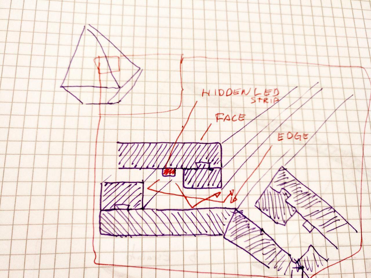
where I think the led strip should go and how painful it’s going to be mount the Monolith. Volume 3
So let’s try to investigate how the adafruit neopixels works. Because these addressable leds can help me with this.
So let’s try to design with adafruit neopixels.
Um. That seems quite expensive (I guess I have 7 faces of 1 meters of perimeter that would be adding a lot of cost to the Monolith) that goes over 100 euros just in lights!
But let’s keep with these. Then I’ll figure out what can I find for less money.
Audio in the attiny1614
Ok, so let’s try to make a board. This is written after the final project was presented.
For the Input I’m going to try to use this
And for the output the notes of Keane.
All within a Attiny1614 board. And I hope that I can get also a I2C connection somewhere so I can connect it to the Monolith!
So I need a free pin and a ground. Let’s get the info of the other pinouts to make the board.
Here in the week of electronic design I’m going to talk about the board.
Programming the same audio that I hand
Ok, so now I tested another blink program to remember how was the toolchain to program it and confirm that the things I did were not a dream.
And now let’s go back to program the same song I have.
First we have that the program says “led_pin” and also it’s a number. For a reason that I don’t know when I did the blink I needed to put “A1” instead of 1. So I have to change it. For that I went to the forums and someone very trustful with a bart avatar came into my help
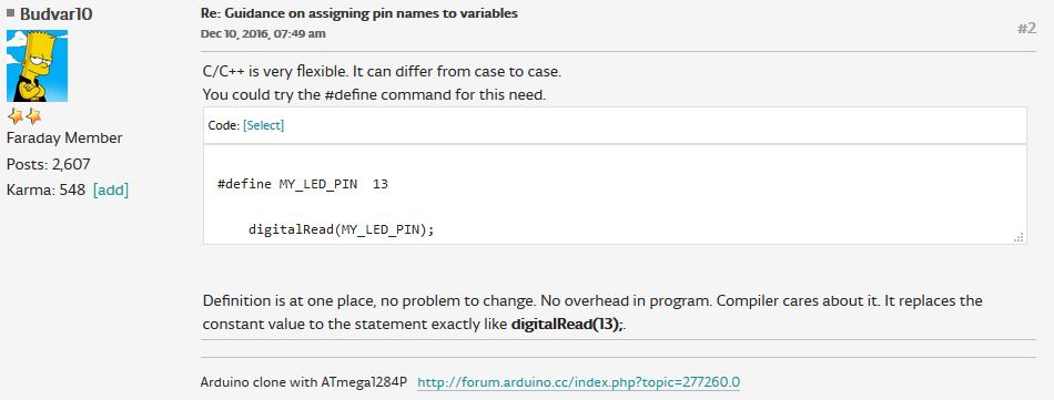
Thanks, el Barto
And also it seems that my magical tool, “analogWriteFreq(frequency);” doesn’t work here. And here there is something that I saw. about it.
So let’s make try little by little
If I do this:
#define AUDIO_OUT_PIN A3

void setup() {

}

void loop() {
  // increase the LED brightness
  for(int dutyCycle = 0; dutyCycle < 1023; dutyCycle++){
    // changing the LED brightness with PWM
    analogWrite(AUDIO_OUT_PIN, dutyCycle);
    delay(1);
  }

  // decrease the LED brightness
  for(int dutyCycle = 1023; dutyCycle > 0; dutyCycle--){
    // changing the LED brightness with PWM
    analogWrite(AUDIO_OUT_PIN, dutyCycle);
    delay(1);
  }
}
This is the result
To look of how to change the frequency I found this useful link https://github.com/SpenceKonde/megaTinyCore/blob/master/megaavr/extras/TakingOverTCA0.md of the library and I’m going to try a tuned example.
#if defined(MILLIS_USE_TIMERA0)||defined(__AVR_ATtinyxy2__)
#error "This sketch takes over TCA0, don't use for millis here.  Pin mappings on 8-pin parts are different"
#endif
#define AUDIO_OUT_PIN A3

unsigned int Period=0xFFFF;

void setup() {
  // We will be outputting PWM on PB0
  pinMode(AUDIO_OUT_PIN, OUTPUT); //PB0 - TCA0 WO0, pin7 on 14-pin parts
  TCA0.SPLIT.CTRLA=0; //disable TCA0 and set divider to 1
  TCA0.SPLIT.CTRLESET=TCA_SPLIT_CMD_RESET_gc|0x03; //set CMD to RESET, and enable on both pins.
  TCA0.SPLIT.CTRLD=0; //Split mode now off, CMPn = 0, CNT = 0, PER = 255
  TCA0.SINGLE.CTRLB=(TCA_SINGLE_CMP0EN_bm|TCA_SINGLE_WGMODE_SINGLESLOPE_gc); //Single slope PWM mode, PWM on WO0
  TCA0.SINGLE.PER=Period; // Count all the way up to 0xFFFF
  // At 20MHz, this gives ~305Hz PWM
  TCA0.SINGLE.CMP0=0;
  TCA0.SINGLE.CTRLA=TCA_SINGLE_ENABLE_bm; //enable the timer with no prescaler
  Serial.begin(9600);
}

void loop() { // Not even going to do anything in here
  Serial.println("150KHz");
  PWMDemo(150000);//150kHz
   Serial.println("70KHz");
  PWMDemo(70000);//70kHz
   Serial.println("15KHz");
  PWMDemo(15000);//15kHz
   Serial.println("3KHz");
  PWMDemo(3000);//3kHz
     Serial.println("440Hz");
  PWMDemo(440);//440Hz
   Serial.println("120Hz");
  PWMDemo(120);//120Hz
  Serial.println("35Hz");
  PWMDemo(35);//35Hz
  Serial.println("13Hz");
  PWMDemo(13);//13Hz
}

void PWMDemo(unsigned long frequency){
  setFrequency(frequency);
  setDutyCycle(64); //~25%
  delay(4000);
  setDutyCycle(128); //~50%
  delay(4000);
  setDutyCycle(192); //~75%
  delay(4000);
}

void setDutyCycle(byte duty) {
  TCA0.SINGLE.CMP0=map(duty,0,255,0,Period);
}

void setFrequency(unsigned long freqInHz) {
  unsigned long tempperiod=(F_CPU/freqInHz);
  byte presc=0;
  while (tempperiod>65536 && presc<7) {
    presc++;
    tempperiod=tempperiod>>(presc>4?2:1);
  }
  Period=tempperiod;
  TCA0.SINGLE.CTRLA=(presc<<1)|TCA_SINGLE_ENABLE_bm;
  TCA0.SINGLE.PER=Period;
}
The serial works but I don’t hear a sound. So let’s try using the pin that it’s asking for (PB0) instead of PA3 that I have in my board. Maybe there is something I’m missing.
Now trying to make it work I had to convert the amplitude function into byte because if I don’t it won’t sound at all.
Now I have a problem because it doesn’t make properly the silences.
Instead of analogwrite I have to use a setdutyCycle(0) and it works. Here is the full code with the Bedshaped score (well, part of it)
#if defined(MILLIS_USE_TIMERA0)||defined(__AVR_ATtinyxy2__)
#error "This sketch takes over TCA0, don't use for millis here.  Pin mappings on 8-pin parts are different"
#endif
#define AUDIO_OUT_PIN B0

const unsigned long freqs[] = {261.63, 293.66, 329.63, 349.23, 392, 440, 466.16, 523.25, 587.33, 587.33, 659.25,698.46, 783.99, 880, 932.33, 1046.50};
int crotchet_milliseconds = 792;
int noise_level = 0;
int time_between_notes = 35;

unsigned int Period=0xFFFF;

void setup() {
  // We will be outputting PWM on PB0
  pinMode(PIN_PB0, OUTPUT); //PB0 - TCA0 WO0, pin7 on 14-pin parts
  TCA0.SPLIT.CTRLA=0; //disable TCA0 and set divider to 1
  TCA0.SPLIT.CTRLESET=TCA_SPLIT_CMD_RESET_gc|0x03; //set CMD to RESET, and enable on both pins.
  TCA0.SPLIT.CTRLD=0; //Split mode now off, CMPn = 0, CNT = 0, PER = 255
  TCA0.SINGLE.CTRLB=(TCA_SINGLE_CMP0EN_bm|TCA_SINGLE_WGMODE_SINGLESLOPE_gc); //Single slope PWM mode, PWM on WO0
  TCA0.SINGLE.PER=Period; // Count all the way up to 0xFFFF
  // At 20MHz, this gives ~305Hz PWM
  TCA0.SINGLE.CMP0=0;
  TCA0.SINGLE.CTRLA=TCA_SINGLE_ENABLE_bm; //enable the timer with no prescaler
  Serial.begin(9600);
}

void sound(unsigned long frequency, int noise, int miliseconds)
{

  setFrequency(frequency);
  byte max_amplitude = 128;
  for (miliseconds; miliseconds > 0; miliseconds = miliseconds -10)
  {
  byte amplitude = max_amplitude + random(16) * noise;
  setDutyCycle(amplitude);
  delay(10);
  }

}

void note(int note_code, float duration, boolean ending = true)
{
  int note_miliseconds = crotchet_milliseconds * duration;
  //first determine if it's silence or note
  if (note_code == -1){
    Serial.println("Silence");
    setDutyCycle(0); //make no sound
    delay(duration);
    return;
  }
  Serial.println("Note");
  unsigned long frequency = freqs[note_code];
  //if it's a note full note send the duration minus an extra delay of silence
  if (ending == true) {

    note_miliseconds = note_miliseconds - time_between_notes;
    sound(frequency, noise_level, note_miliseconds);
    setDutyCycle(0);//make no sound
    delay(time_between_notes);
  }
  else {
    sound(frequency, noise_level, note_miliseconds);
  }
}

void loop() {
      Serial.println("Starting loop");
      note( 4 , 0.25 , true );
      note( 10 , 0.25 , true );
      note( 10 , 0.75 , true );
      note( 10 , 0.25 , true );
      note( 10 , 0.75 , true );
      note( 5 , 0.5 , true );
      note( 6 , 0.5 , true );
      note( 7 , 2 , true );
      note( -1 , 2.5 , true );
      note( 7 , 0.25 , true );
      note( 7 , 0.75 , true );
      note( 13 , 0.25 , true );
      note( 13 , 0.75 , true );
      note( 12 , 0.25 , true );
      note( 13 , 0.75 , true );
      note( 12 , 1 , true );
      note( 8 , 1.5 , true );
      note( -1 , 3 , true );
      note( 6 , 0.25 , false );
      note( 7 , 0.25 , true );
      note( 9 , 0.25 , true );
      note( 11 , 0.75 , true );
      note( 11 , 0.25 , true );
      note( 11 , 1.25 , true );
      note( 6 , 0.5 , true );
      note( 7 , 0.5 , true );
      note( 8 , 1.5 , true );
      note( -1 , 2.5 , true );
      note( 7 , 0.25 , true );
      note( 7 , 0.75 , true );
      note( 13 , 0.50 , true );
      note( 13 , 0.50 , true );
      note( 12 , 0.50 , true );
      note( 13 , 0.50 , true );
      note( 12 , 0.50 , true );
      note( -1 , 0.5 , true );
      note( 8 , 0.5 , true );
      //tercer pentagrama
      note( 9 , 3 , true );
      note( 9 , 0.5 , true );
      note( 10 , 2.5 , true );
      note( -1 , 1 , true );
      note( 10 , 0.5 , true );
      note( 10 , 3.5 , true );
      note( 10 , 0.5 , true );
      note( 10 , 1.5 , true );
      note( -1 , 0.75 , true );
      note( 10 , 0.25 , true );
      note( 11 , 0.25 , true );
      note( 11 , 0.25 , true );
      note( 11 , 0.25 , true );
      note( 11 , 0.59 , true );
      note( 9 , 0.33 , true );
      note( 9 , 0.33 , true );
      //cuarto pentagrama
      note( 9 , 0.33 , true );
      note( 8 , 0.33 , true );
      note( 9 , 0.34 , true );
      note( 12 , 2.5 , true );
      note( 12 , 0.25 , true );
      note( 12 , 1.25 , false );
      note( 13 , 0.5 , true );
      note( 11 , 1.5 , true );
      note( -1 , 0.5 , true );
      note( 10 , 1 , false );
      note( 11 , 3 , true );
      note( 9 , 0.5 , true );
      note( 11 , 0.75 , true );
      note( 11 , 0.75 , true );
      note( 9 , 1.5 , true );
      note( -1 , 0.5 , true );
      note( 9 , 0.5 , true );
      //quinto pentagrama
      note( 9 , 0.33 , true );
      note( 8 , 0.33 , true );
      note( 9 , 0.34 , true );
      note( 12 , 2.5 , true );
      note( 12 , 0.25 , true );
      note( 12 , 1.25 , false );
      note( 13 , 0.5 , true );
      note( 11 , 1.5 , true );
      note( 10 , 0.5 , true );
      note( 10 , 1 , false );
      note( 11 , 1.5 , true );
      note( -1 , 1.5 , true );
      note( 9 , 0.5 , true );
      note( 11 , 0.75 , false );
      note( 10 , 0.75 , false );
      note( 9 , 1.5 , true );
      note( -1 , 0.75 , true );
      note( 9 , 0.25 , true );
      //sexto pentagrama
      note( 10 , 0.5 , true );
      note( 9, 0.25, true);
      note( 10 , 0.75 , true );
      note( 11 , 1.5 , true );
      note( -1 , 1 , true );
      note(10, 0.5, false);
      note(9, 0.25, false);
      note(10, 1.25, true);
      note(11, 0.25, false);
      note(12, 0.25, false);
      note(11, 1, false);
      note(10, 1, true);
      note(10,0.25,false);
      note(10,1.5, true);
      note(-1,0.75, true);
      note(4,0.25, true);
      note(4, 0.5, true);
      note(11, 0.25, true);
      note(11, 0.75, true);
      note(11, 0.25, true);
      note(11, 0.75, true);
      note(6, 0.5, false);
      note(7, 0.5, true);
      //septimo pentagrama
      note(8, 1.5, true);
      note(-1, 2.5, true);
      note(8, 0.25, true);
      note(8, 0.25, true);
      note(8, 0.5, true);
      note(14, 0.25, true);
      note(14, 0.75, true);
      note(14, 0.25, true);
      note(14, 0.75, true);
      note(13, 1, true);
      note(8, 1.5, true);
      note(-1, 2.25, true);
      note(6, 0.25, true);
      note(6, 0.25, true);
      note(6, 0.5, true);
      note(7, 0.25, false);
      note(9, 0.25, true);
      note(11, 0.75, true);
      note(11, 0.25, true);
      note(11, 0.75, true);
      note(6, 0.5, false);
      note(7, 0.5, false);
      note(8, 0.5, false);
}


void setDutyCycle(byte duty) {
  TCA0.SINGLE.CMP0=map(duty,0,255,0,Period);
}

void setFrequency(unsigned long freqInHz) {
  unsigned long tempperiod=(F_CPU/freqInHz);
  byte presc=0;
  while (tempperiod>65536 && presc<7) {
    presc++;
    tempperiod=tempperiod>>(presc>4?2:1);
  }
  Period=tempperiod;
  TCA0.SINGLE.CTRLA=(presc<<1)|TCA_SINGLE_ENABLE_bm;
  TCA0.SINGLE.PER=Period;
}