
8.
Embedded Programming
Assignments
group project:
compare the performance and development workflows for other architectures
individual project:
read a microcontroller data sheet
program your board to do something,
with as many different programming languages
and programming environments as possible
Download the files
This week the only thing to download is the source code of the examples below.
Download source code filesTable of contents
-
Making my board a bit more complex
-
Arduino IDE
-
Setting up the IDE
- Adding Additional Boards to the Manager with URLs
- Installing esp32 in Board Managers
- Adding lsusb to Terminal on Mac
- Tools > Board, Port & Programmer
-
Building, compiling & uploading
-
Platformio
-
Setting up Platformio
- Installing it via Homebrew
- Mkdir + Platformio
- Looking for boards with grep
- Initialising the project with the board ID
- The configuration file: platformio.ini
-
Building, compiling and uploading
-
Using a different framework: ESP-IDF
-
Let’s code something… exciting.
-
In C/C++
- Finding some weather accessing libraries
- Using the DarkSkySevenDay
- Flashing the ESP32 board with the code…
- Using ESP8266 Weather Station API
- Just adding a simple Farenheit to Celsius conversion
- Difference between C and C++
-
In Python
- Wait… the board only reads C
- Installing MicroPython
- Establishing a serial connection
- Playing around in the console
- Something about reading Serial though...
- I’d like to listen for an event… or say “hey, this button was pushed”
-
In Arduino (high level C++)
Have you?
Making my board a bit more complex
Adding components

Adding the buttons
Not too much to say about this, make sure there are resistors, almost whatever value works (I used 10MΩ because that’s what I had).


Adding the RGB LED
It has a Common Cathode (-) which means it needs three I/Os as power source and they all connect to GND. Again, add a resistor here. I put a 330Ω one, although 220 is standard, just to make sure things don’t explode.
Connecting all to breadboard
Easy stuff.
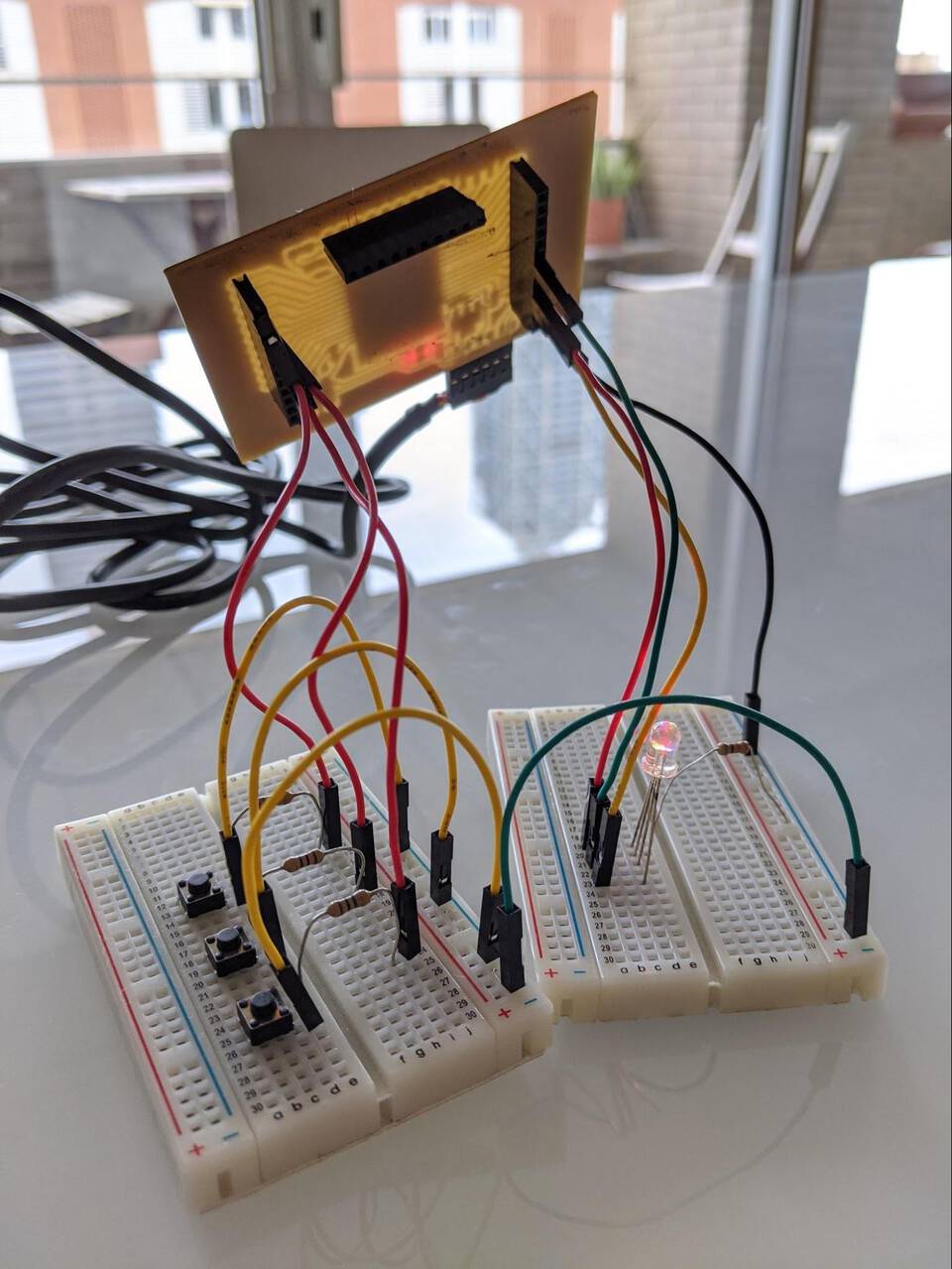 “Weeeee” - the board
Arduino IDE
Setting up the IDE
First you need to tell the Arduino IDE what board we are going to use, where to find all the info it needs.
Adding Additional Boards to the Manager with URLs


Installing esp32 in Board Managers


Adding lsusb to Terminal on Mac
I know that on Linux by default you have lsusb which is similar to the ls command, but for usb devices. I like it because it’s easy to remember and clean.
Unfortunately on Mac it doesn’t come pre-installed. After some quick Googling I found that somebody added it to the Homebrew library.
Easy to install brew install lsusb

You can see that by plugging only the cable, you get the Future Technology Devices International (FTDI) device showing up.
Note //it shows “Serial: FT9P04G3”. It will be useful for the next step.
I also made my own FTDI cable, available here. It uses an FT230X chip.
Tools > Board, Port & Programmer
You have to tell the IDE what board we are using, which port and how to program it.
- Board: Select the ESP32 Dev Module. This automatically fills the 8 dropdown menus
- Port: I selected the one that seemed the least normal, but also, and this makes more sense, it has shows FT9P04G3 which is the Serial we noted in the previous step
- Programmer: In this case I picked ArduinoISP because it sounded like it could work… and it did

Building, compiling & uploading
Blink example on the board
In the Arduino IDE you can load a simple example to test your board. In this case let’s use Blink, as it seems it’s the one EVERYBODY DOES ALL THE TIME.
Also we have an LED on the board, so that makes sense as well.
The default program has LED_BUILTIN, which is a definition for the pin where the builtin LED in Arduino’s are.
We have to change it as we are not using an Arduino, but a custom made board, with an ESP32-WROOM chip on it.
Reading the datasheet of ESP32 to find out which I/O instead of LED_BUILTIN
Obviously I left LED_BUILTIN in the code, so it wouldn’t work. You need to find the pin where the LED is connected to.
You can find that out by looking at the design of the Barduino 2.0 (designed for the MDEF Masters, but we built a few in a rush before the Fab Lab closed because of COVID-19). It shows lower in the page, what I/Os are connected to the LED.

You can also find it out by looking at the board (that’s what I did the first time), see where the LED is connected (bottom-left), and figure out from the datasheet what the pin is.
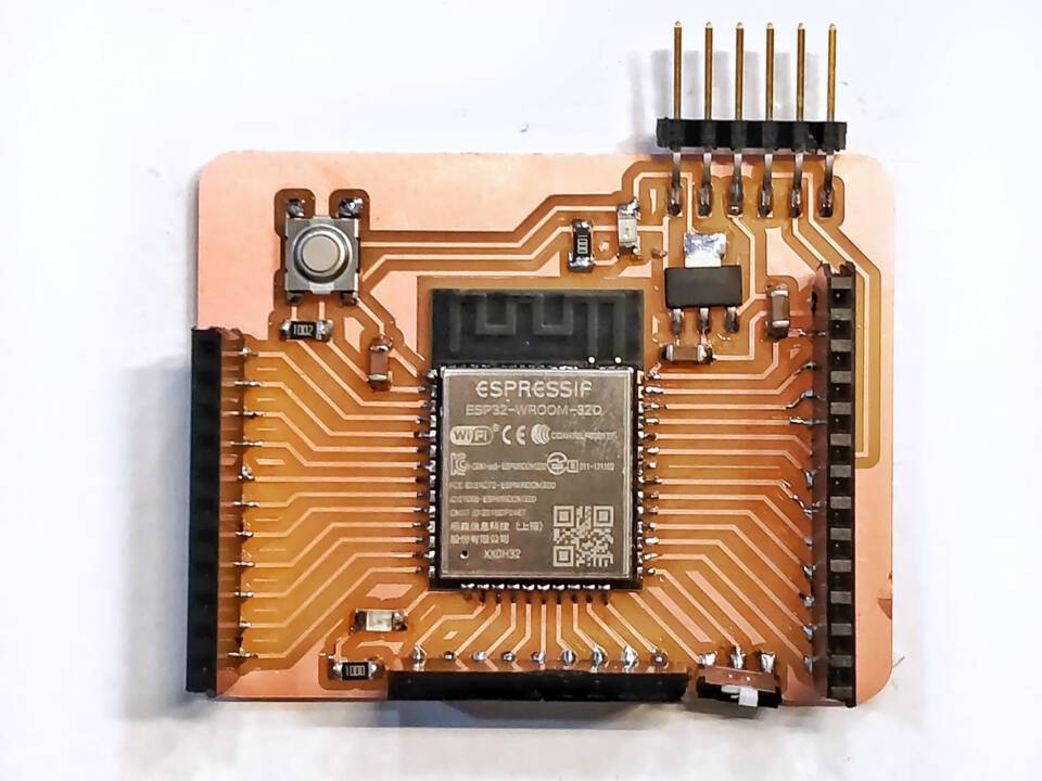
By checking the datasheet of the ESP32, scrolling to Pin Layout , you can see the LED is connected to pin number 16 …

… but the actual number you want to use is 13, as it is in the Pin Name.

Compiling and uploading the code
As expected, it compiled and uploaded without a problem. Success!

Let’s try it on Platformio now…
Platformio
Following this tutorial: http://fabacademy.org/2020/labs/barcelona/local/#material/extras/week08/platformio
And this one: https://docs.platformio.org/en/latest/core/quickstart.html#initialize-project
Setting up Platformio
Installing it via Homebrew
You can install Platformio either with pip install -U platformio or brew install platformio.
I use brew quite a lot and prefer to install everything, as much as possible, through it. It means that in the future if I need to uninstall or upgrade anything, I know which packet manager to go to.
Mkdir + Platformio
As always, we open a good ol’ iTerm 2 window, and in this case create a folder for our project, and move into it:
mkdir Platformio
cd Platformio
Looking for boards with grep
Now we need to initialise our project, but first we’ll tell Platformio what board we’ll be using.
We can browse their library with pio boards … I know my chip is by Espressif, so I’ll type in pio boards espressif... that’s too many results.
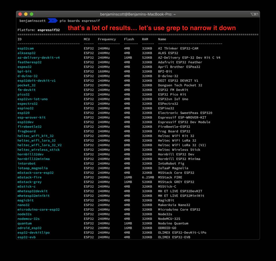
Let’s try pio boards esp32-.
I put a dash hoping it would narrow down to find the ESP32-WROOM which is what is written on my chip.
I can’t find the ESP32-WROOM but found another few options which all seem similar (same RAM, frequency, etc.), so I picked one: esp32-devkitlipo

Initialising the project with the board ID
To initialise the project
pio project init -board esp32-devkitlipo

The creates the corresponding platformio.ini file which declares the environment we are working with.
The configuration file: platformio.ini
This file is pretty simple after the initialisation, for now it only contains
                    [env:esp32-devkitlipo]

                    platform = espressif32

                    board = esp32-devkitlipo

                    framework = arduino
Building, compiling and uploading
Processing the Pio project
Let’s enter pio run which processes (builds) all environments specified in platformio.ini (Project Configuration File) without uploading it to any devices.

On the left is the code we’ll upload to the board, the standard Blink example.
Here’s the verbose:
Processing esp32-devkitlipo (platform: espressif32; board: esp32-devkitlipo; framework: arduino)
-----------------------------------------------------------------------------------------------------
PlatformManager: Installing espressif32
Downloading [####################################] 100%
espressif32 @ 1.11.2 has been successfully installed!
The platform 'espressif32' has been successfully installed!
The rest of packages will be installed automatically depending on your build environment.
PackageManager: Installing toolchain-xtensa32 @ ~2.50200.0
Downloading [####################################] 100%
Unpacking [####################################] 100%
toolchain-xtensa32 @ 2.50200.80 has been successfully installed!
PackageManager: Installing framework-arduinoespressif32 @ ~3.10004.191002
Downloading [####################################] 100%
Unpacking [####################################] 100%
framework-arduinoespressif32 @ 3.10004.200129 has been successfully installed!
PackageManager: Installing tool-esptoolpy @ ~1.20600.0
tool-esptoolpy @ 1.20600.0 has been successfully installed!
CorePackageManager: Installing tool-scons @ ~3.30102.0
tool-scons @ 3.30102.0 has been successfully installed!
Verbose mode can be enabled via `-v, --verbose` option
CONFIGURATION: https://docs.platformio.org/page/boards/espressif32/esp32-devkitlipo.html
PLATFORM: Espressif 32 1.11.2 > OLIMEX ESP32-DevKit-LiPo
HARDWARE: ESP32 240MHz, 320KB RAM, 4MB Flash
DEBUG: Current (esp-prog) External (esp-prog, iot-bus-jtag, jlink, minimodule, olimex-arm-usb-ocd, olimex-arm-usb-ocd-h, olimex-arm-usb-tiny-h, olimex-jtag-tiny, tumpa)
PACKAGES:
- framework-arduinoespressif32 3.10004.200129 (1.0.4)
- tool-esptoolpy 1.20600.0 (2.6.0)
- toolchain-xtensa32 2.50200.80 (5.2.0)
LDF: Library Dependency Finder -> http://bit.ly/configure-pio-ldf
LDF Modes: Finder ~ chain, Compatibility ~ soft
Found 26 compatible libraries
Scanning dependencies...
No dependencies
Building in release mode
Compiling .pio/build/esp32-devkitlipo/src/main.cpp.o
Generating partitions .pio/build/esp32-devkitlipo/partitions.bin
Archiving .pio/build/esp32-devkitlipo/libFrameworkArduinoVariant.a
Indexing .pio/build/esp32-devkitlipo/libFrameworkArduinoVariant.a
Compiling .pio/build/esp32-devkitlipo/FrameworkArduino/Esp.cpp.o
Compiling .pio/build/esp32-devkitlipo/FrameworkArduino/FunctionalInterrupt.cpp.o
Compiling .pio/build/esp32-devkitlipo.pio/build/esp32-devkitlipo/FrameworkArduino/wiring_pulse.c.o
Compiling .pio/build/esp32-devkitlipo/FrameworkArduino/wiring_shift.c.o
Archiving .pio/build/esp32-devkitlipo/libFrameworkArduino.a
Indexing .pio/build/esp32-devkitlipo/libFrameworkArduino.a
Linking .pio/build/esp32-devkitlipo/firmware.elf
Building .pio/build/esp32-devkitlipo/firmware.bin
Retrieving maximum program size .pio/build/esp32-devkitlipo/firmware.elf
Checking size .pio/build/esp32-devkitlipo/firmware.elf
Advanced Memory Usage is available via "PlatformIO Home > Project Inspect"
RAM: [ ] 4.7% (used 15348 bytes from 327680 bytes)
Flash: [== ] 16.1% (used 210941 bytes from 1310720 bytes)
esptool.py v2.6
============ [SUCCESS] Took 21.96 seconds ============
My eyes were drawn in the verbose, to a link about docs for the board, it led here: the documentation for the OLIMEX ESP32-DevKit-LiPo. This page has a link to the Github repository which contains its Board Manifest (the JSON file that tells Platformio everything it needs to know)
Note //There’s a link where you can buy this board, and you can see it has the right chip.
I got curious the check the other boards on the Github repository, and was my gaze was once again stolen by esp32dev, which when clicked on, shows that it’s full name is Espressif ESP32 Dev Module which is what we used this morning as a Board in the Arduino IDE. Promising.
Let’s search the boards again, but using grep with “Espressif ESP32 Dev Module”...

That’s it!
Its ID is esp32dev, as we could have imagined.
Let’s open the platformio.ini file and change the board id.
nano platformio.ini
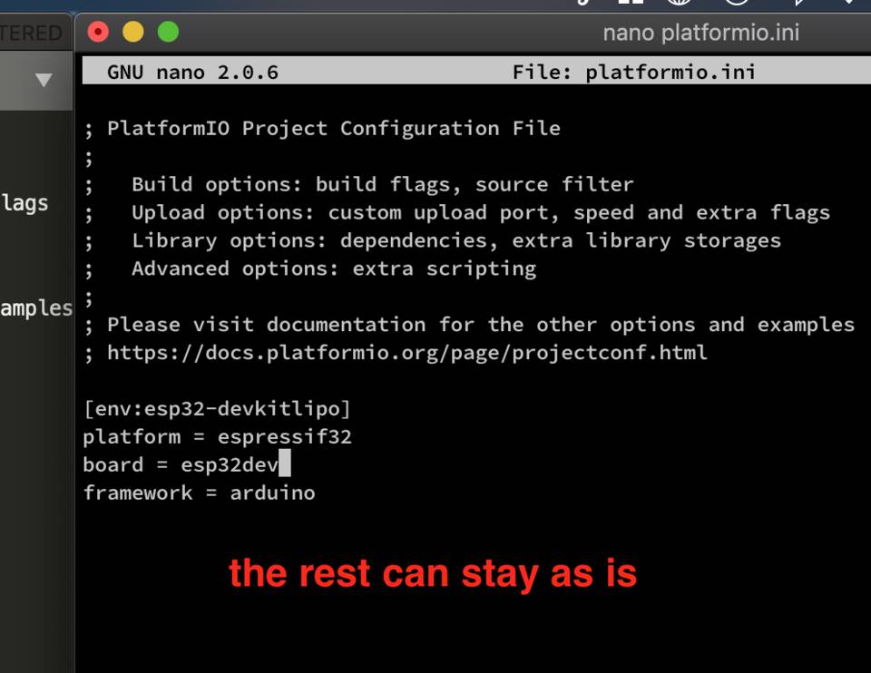
Runnin pio run again, and finally uploading
Let’s run pio run again. Same success messages. Below is a screenshot of the directories and files it created, ready to flashed into the chip.

Let’s run pio run -t upload

The board blinks, it’s working.
Trying it with the esp32-devkitlipo id
As expected, using the original ID I found, it worked just the same.
Conclusion and thoughts
I still wonder why I didn’t have to setup flags, tell it what port to use, etc.
I think that, as we told Platformio what board we were using, it knew what to do with the fuses, and the configuration file in general, but what about the port? Did it just try multiple one until it worked?

I’m sad because I made a board which had three buttons and an RGB LED, but I left it at the Fab Lab, and it’s now shut for at least a month. It’s annoying because it was an ATtiny1614 chip, and therefore doesn’t seem to be as easy as the ESP32 to program. Maybe it is, I don’t know.
Luckily I was donated a box of electronic toys the other day, including breadboards, so I will be able to create temporary circuits and play around with the code a bit more.
Talking about code, so far it’s been pretty boring. We’re just making an LED blink more or less fast… let’s try and take it to another level…
Using a different framework: ESP-IDF
So far we’ve been using the Arduino framework to code for our ESP32. Espressif, the company that develops the ESP32, has a few of their own frameworks.
For this part I’ll use ESP-IDF, following this tutorial.
Setting up the tools
Can’t run ./install.sh
I was following the tutorial and arrived at this point, when I ran ./install.sh it gave me this error ./install.sh: line 9: /Users/benjaminscott/Documents/Fab: No such file or directory.
Basically the path invoked in the script isn’t escaped, which means that because I have directories with a space in their name, the bash script stops there.
I have to escape the line for it to work.
Google search time… here we are. You can add quotes around the path by simply adding quote around ${PATH}


I can run it, but now it fails to download some assets
Now the ./install.sh can run without a problem… well, with another problem. You can see a fair few “WARNING: Download failure”.

I copy and pasted the errors and opened them in TextEdit to see what it was trying to download, and how many different thing is it downloading.
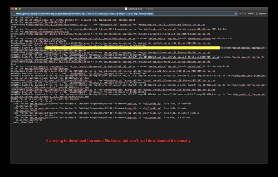
I went to the link and downloaded the file.

But then noticed that, actually the link shows up 3 times, and the third time it was downloaded fine…
I opened up the idf_tools.py script which downloads and installs all these scripts, and went to the line it was announcing an error. It pointed to a download() function, and in it you could see it tried to download the files multiple times… if that’s the case it must be an error they are used to encounter… let’s see if just re-run the ./install.sh script.

It works fine… all downloaded, all happy… for now.
Now it isn’t running . ./export.sh
It says to run . ./export.sh … but doesn’t work, it gives an error.

It says “IDF_PATH must be set before sourcing this script.”
Let’s check the export.sh file: nano export.sh - it seems half of it is the script trying to figure out a path itself. I just added one line at the top which I copied and pasted from the install.sh file, not forgetting to add the quotes around:
export IDF_PATH="$(cd $(dirname $0); pwd)"

What’s next on the list of things to not work?
I did idf.py menuconfig and it’s been downloading for 20 mins… loads of libraries.
Edit, 2 hours later: Ookkkk, so, it downloaded stuff, but once again failed because of directory names, etc.

F*ck it, I abandon, don’t have time to figure this useless stuff out. Could restart from scratch in the same folder structure as the tutorial (~/esp) but more waste of time. I better get coding now.
Let’s code something… exciting.
I’ve played around a bit with Python and I’m not too scared of it… but my first experience with programming was when I was 15 and decided that I wanted to learn how to.
For some reason I went with C (because it was the most powerful and I wanted to code games). I stayed with it for a few months, but then got discouraged.
I should have followed the online advice of starting with Python. Who knows, my life could be completely different today!
For my final year project I’m going to connect to some weather data, and dim the LED strips more less depending on it. I thought for this week I could try and make an LED flash at a certain speed depending on the temperature.
In C/C++
Finding some weather accessing libraries
My first test I did with the project was using the Dark Sky API with Python… but now we are in C. I found on their website there’s a C++ library. Then I thought… wait, maybe it’s already available in the Manage Libraries of Arduino.
Let’s check… no, not this one, but there’s a few other options we could play with. Let’s try.

Using the DarkSkySevenDay
If you click on More info it sends you this page. It seems simple, but there’s a few things to set up.
On the page it says to simply run getWeather(GKEY, DKEY) for it to work, but obviously you also need to get the ESP32 to connect to the internet.
In the example folder there’s a code example of how to set up the entire project.
There’s a thing though… when I Verify the code it throws me an error:
class ‘DarkSkySevenDay’ has no member called ‘getWeather’
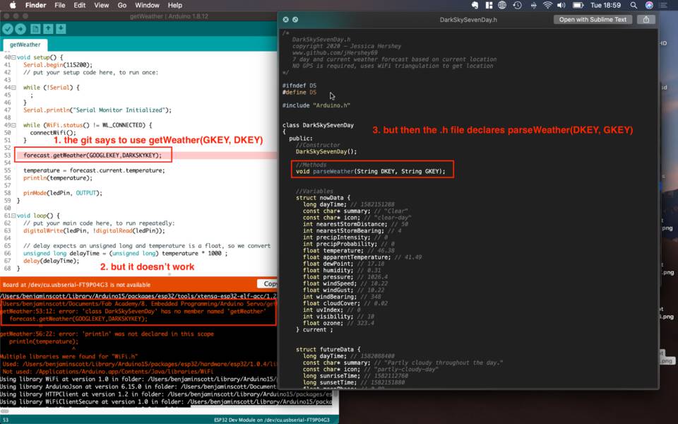
It’s because for some reason, even in the example given, it calls the method getWeather() when in the .h file it’s declared parseWeather()... let’s change it and Verify it.
Yep, it all works.
Flashing the ESP32 board with the code…
It works as well.
The thing is… it wasn’t very satisfying. I figured out how to connect to API and all, and it’s cool, but you want it to do more things. Code more in C. What else can be done?
Using ESP8266 Weather Station API
This one might be even easier. (Edit: actually it isn’t).
I just replaced the connectWifi() function by the one from the previous project as it worked.
Replaced the “ESP8266WiFi.h” by “Wifi.h”, and deleted the line ‘‘‘ const char* ESP_HOST_NAME = "esp-" + ESP.getFlashChipId(); ‘‘‘
It throws loads of errors saying uint32_t does not name a type but I found this, which solves it: you just need to include the <stdint.h> library.
Next error? Ah, well, there seemed to be way less errors after last step, but it’s because I accidentally typed “w” at the start of the script so it crashed early.
It seems to have a problem with WiFiClient.h… it’s always calling it. I thought, maybe somewhere in the WiFiClient.h it wants ESP8266WiFi.h, so I added it back in, but it says it doesn’t exist because my selected chip is an ESP32.
Ok, let’s abandon this, the script was obviously for the old chip and I can’t make it work for the ESP32, we’re just wasting time.
Just adding a simple Farenheit to Celsius conversion
If I’m not gonna code much, let’s at least code some stuff. The formula to convert Farenheit to Celsius is: C = (F - 32) / 1.8
In C++ code it gives:
float farToCelsius(float farenheit) {
	return (farenheit - 32) / 1.8;
}
Difference between C and C++
Explained here, basically C++ as an evolution of C and introduces Classes and Objects.
In Python
Wait… the board only reads C
Yes, but you can use some platform that allows you to install a miniOS which can run Python. One of these is called MicroPython.
MicroPython is a lean and efficient implementation of the Python 3 programming language that includes a small subset of the Python standard library and is optimised to run on microcontrollers and in constrained environments. You also get an interactive prompt (the REPL) to execute commands immediately, along with the ability to run and import scripts from the built-in filesystem.
Installing MicroPython
You just need to follow these instructions really. Make sure you add the right port. You can list them with ls /dev/cu.* which lists all devices that are USB. In Linux you’d replace cu by tty.

This installs MicroPython on the ESP32, you can now access it’s Python Console via serial connection (UART).
Establishing a serial connection with the screen command
I didn’t know how to do it, and the tutorial above for some reason didn’t point anywhere… so I googled. I found this, which started very promising, but in the end didn’t actually show me how to do it on Mac. It only showed for Windows and Linux.
Back to Google, and I found this. The answer to the question doesn’t answer my question, but the answer below does: there’s an integrated command on Macs which is screen.
Let’s try it:
screen /dev/cu.usbserial-FT9P04G3 115200
Note //when you launch a screen command, it opens a window and then seems impossible to exit. If you close the window the screening continues, and you can’t later relaunch the command. The solution is to run these two commands.
screen -ls
to see a list of the USB serial, and which ones are Attached (Active)
screen -X -S 14311.ttys000.BenjaminScott quit
to stop the screening
... or an easier one, just unplug and plug back in your USB cable.
Oscar gave me a shortcut to kill the screen command, but I can't remember it...
Ah! Found it! It'sCtrl + A + K, which apparently works in many places.
It works! Nice! Let’s do it again and do a screengrab to show how it works.
Run the command again… ah… it doesn’t work. Why? I press the Reset button on the board, but it doesn’t want to work. I unplug and plug back in the board to the FTDI cable. It doesn’t work. It keeps saying this.

It seems the board is busy… but I keep restarting it so it shouldn’t be.
Ooooh, waiiiit! The device that is connected to the computer is not the ESP32… it’s the FTDI cable! Let’s try and unplug the entire cable from the computer and try again.
Here we gooooo.
Playing around in the console
You can have fun in the Python console.
I managed to switch on and off the LED on pin13 with this code
                        import machine
                        pin13 = machine.Pin(13, machine.Pin.OUT)
                        pin13.value(1)
You can also, more interestingly, scan the networks around with
import network
sta_if = network.WLAN(network.STA_IF); sta_if.active(True)
sta_if.scan() # Scan for available access points
sta_if.connect("<AP_name>", "<password>") # Connect to an AP
sta_if.isconnected() # Check for successful connection
Something about reading Serial though...
When I was playing around with Arduino, I wanted to write to the Serial, to read the state of my LEDs, buttons, etc.
At first it didn’t have anything readable at all… but it made sense because I had copied and pasted the Serial.begin(9600) which uses a completely different Upload Speed than the 921600 the program was being uploaded at.
Edit: the upload speed and baud don’t have nothing to do with eacher other. You set your baud in the Serial() object, and then in the Serial Monitor in Arduino you select the same baud. I’m guessing it’s similar with the screen in Terminal.
I changed the value to Serial.begin(921600) and behold! It didn’t work. I could see “OffOffOffOff” which was a good start, but it didn’t have a stream of data, and a lot of the text was just question marks and unknown characters.
I decided to try with Serial.begin(115200), have the same Upload Speed, and finally screen at the right baud and… it works!
It seems sometimes higher bauds aren’t good. Maybe there intervals in PWN are so small it’s easier to mistake a pulse for something else?
I’d like to listen for an event… or say “hey, this button was pushed”
Can’t put it in the loop, otherwise the function would be called allllll the time. Except if it can only be called once?
https://www.instructables.com/id/Arduino-Push-Switch-Debouncing-Interrupts/
In Arduino (high level C++)
Documentation for coding in Arduino: https://www.arduino.cc/reference/en/
I decided to follow this tutorial and trying and manipulate a little servo I have hanging around mine: knob.
A fatal error occured: we can’t upload your stupid code
I was trying to upload some code and it gave me an error.
A fatal error occured: Timed out waiting for packet content

Researching the error I landed on this page, somewhere on this page it said:
“I had a same problem with same board! Problem was that i was pulling GPIO2 to high. If GPIO2 is pulled high, it will not boot.” - Some Geek
I checked, and I wasn’t using GPIO2, but I did have the 3.3V and GND ground connected to a breadboard, that might affect it… and it did. I unplugged them and it uploaded fine.

Oh, and you can’t use analogWrite() either
I managed to read the values of the potentiometer using analogRead() and it worked fine, but when I tried to use analogWrite() then it said that it wasn’t defined in the scope… whatever that means.

Just like the Roman Empire
Google research, aaaand… when you #include <Servo.h> it includes the library to use with Arduino boards. If you try and compile the code I wrote before, but in Tools > Board you pick an Arduino Uno, then it’s fine.
We have an ESP32 though, so we need to download our own library.

… and include it with #include <ESP32Servo.h>
Now it should be fine, right?
Not really. After playing around and installing libraries and all, the servo was still not moving. It emits a little scream of life when I plug it into the board, but then doesn’t move. Why?
Ah… it operates from 4.8V to 6V… I’m feeding it 3.3V.
The ESP32 doesn’t have 5V pins… actually the entire board is only 3.3V logic and power. Well, we have to abandon controlling a servo with the ESP32 then. Good to keep in mind for the future though.