Week 12
Link to the class contentOutput Devices
- Group assignment
Measure the power consumption of an output device
- Individual assignments
Add an output device to a microcontroller board you've designed and program it to do something
- Learning outcomes:
Demonstrate workflows used in circuit board design and fabrication. Implement and interpret programming protocols. - Have you:
Described your design and fabrication process using words/images/screenshots, or linked to previous examples. Explained the programming process/es you used and how the microcontroller datasheet helped you. Outlined problems and how you fixed them. Included original design files and code.
Group assignment
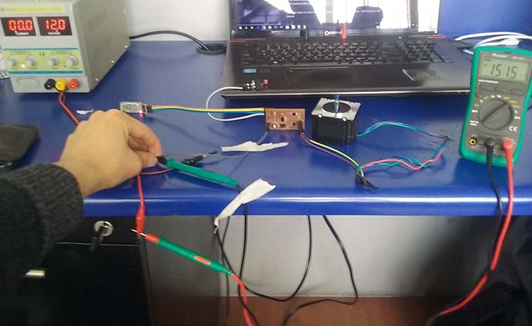
My output device board need 12 Volts to turn on the motor attached to it and also there are another devices attached to it like the bluetooth and the limit switch I measure the current consumed just for my board then my boar with the motor and finally the boar with tall the devices attached.
To do that I had to connect the positive pin from the power supply to the positive pin from the multimeter then the negative pin from the power supply with GND of my board trough a cable after that connect the negative pin of the multimeter with 12V of my board trough a cable.
- Board = 7.36 I
- Board + Motor = 38.79 I
- Board + Motor + Bluetooth + Limit switch = 151.5 I
Current measurement:
- Power = Current X Voltage
- P=IV
- I=151.5 Amps
- V=12 Volts
- P=1812 Watts !
Power consumption of my board with all of the components connected:
Design
Final project
Sketch Plan
For this assignment I design my output devices in relationship with the in-put devices so they can communicate with each other, for that I add the next items:
- Bluetooth: communicate between the circuit board located in one side and the second one at the other side.
- Limit switch: determine the limit position of the shelter.
- Charge module: is about to charge the battery.
- Button: To open and close the shelter.
- Stepper motor (bipolar): Move the shelter from a determined position to another.
You can download the bill of material for the board:
Eagle
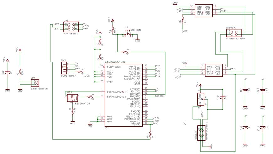
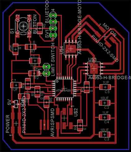
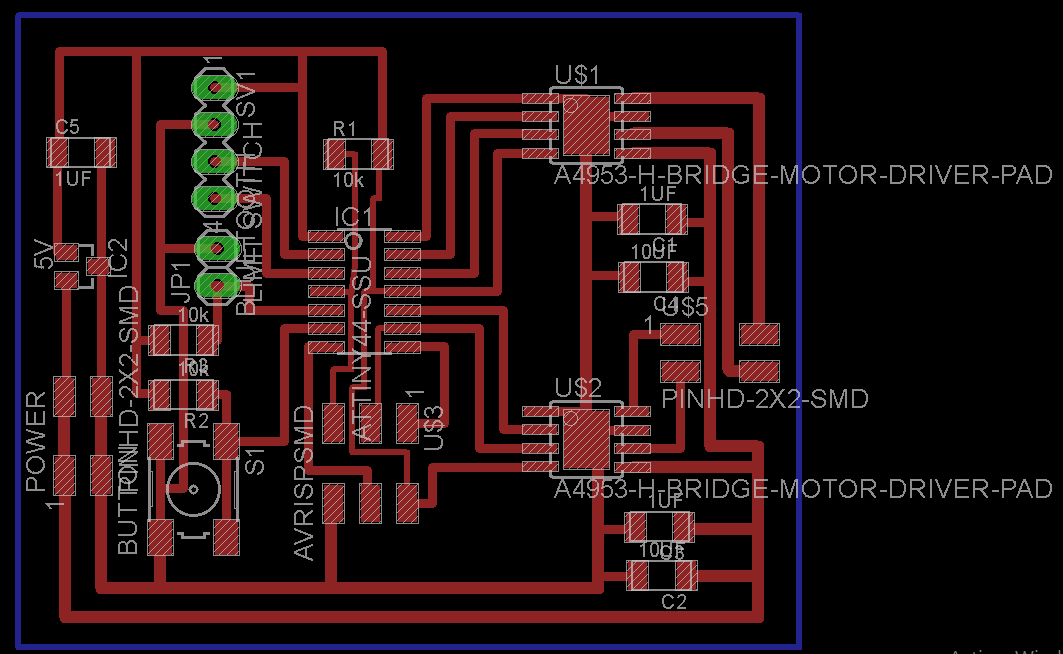
Schematic: this time creating the schematic view was more difficult than the previous times because this time I add more components than before. To know what components I will need for the stepper motor I use Neil's examples board and components as a reference.
For that I did the next process:
- Create a new project called Output.
- Create a new schematic, add the components and organize them.
- Create the connections between them.
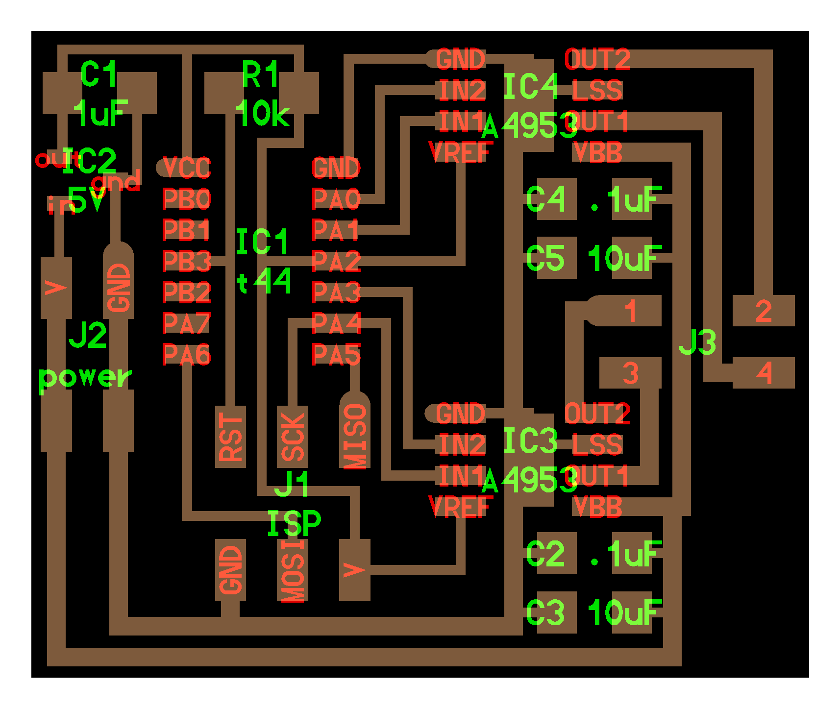
Board: designing the board was easier than before but take me two days to create the connections between the components, because there were to many the most difficult part for me was to connect all of them, for that I returned to the schematic view and add some zero ohm resistor to use them as a bridges.
For that I did the next process:
- Change to the board view.
- Organize all components trying to put the connection of each component near to the micro controller.
- Use the 0 ohm resistor as a bridges.
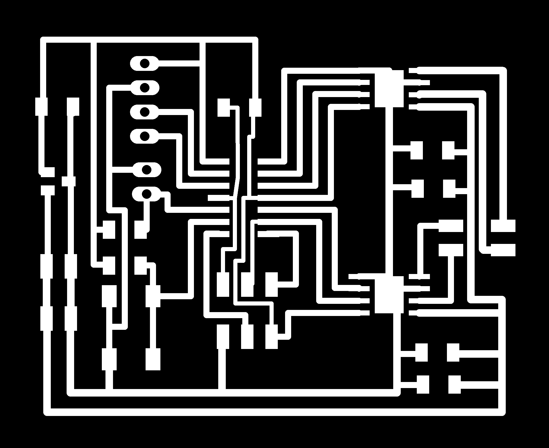
- Use other layer to create the cut line.
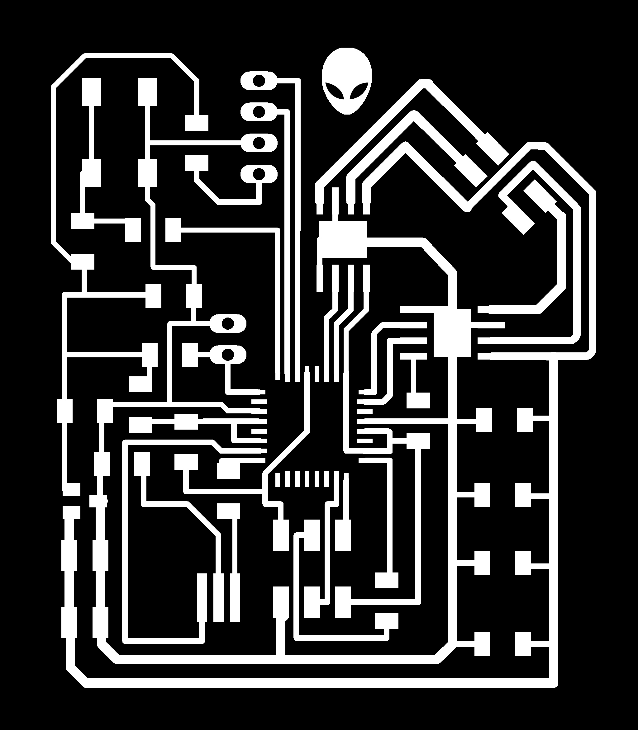
- Export the traces and cut to a PNG file.
You can download the files:
PNG
To edit the files I did the next process:
- Open the png files in Illustrator.
- Open Photoshop and create a new empty file setting the file size that correspond to the PNG file.
- Copy the files from illustrator to Photoshop.
- Edit the files and add an alien face.
- Save as PNG.

Mods
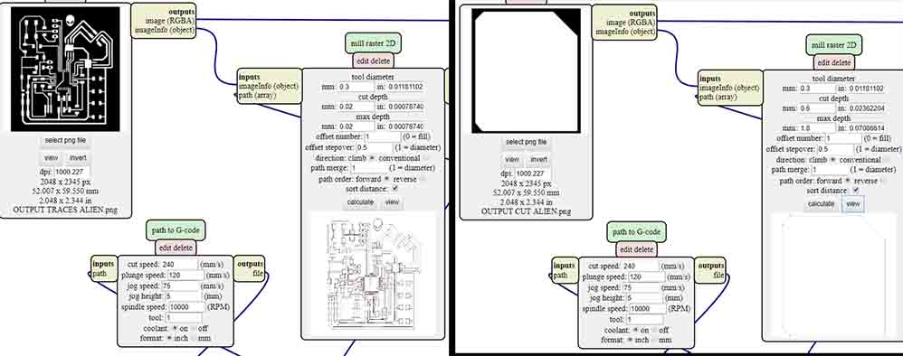
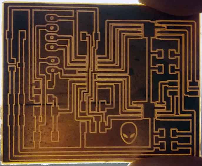
This time I made 3 test before I create the final C-code because the milling cutter with sharp point that we were using breaks before I use it and I had to use a new one with a flat end. For the final C-code I use the next settings:
- Tool diameter : 0.3
- Cut depth: 0.02
- Max depth: 0.02
- Offset number: 1
- Offset stepover: 0.5
- Cut speed:240
- Plunge speed: 120
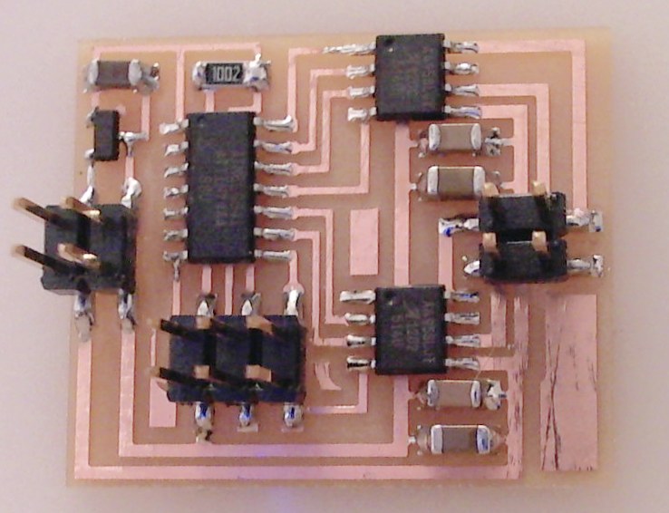
Machining and Soldering
Machining
Before I got my final board I did three test, the fist one with the new milling cutter with the previous configurations that we use but the result was pretty bad most of all the traces disappear, in the second and third attempts I try others milling cutters of 60 degrees that we have in the lab but they didn't work for me because the tip was damaged and the result was rough surface and some traces damaged.
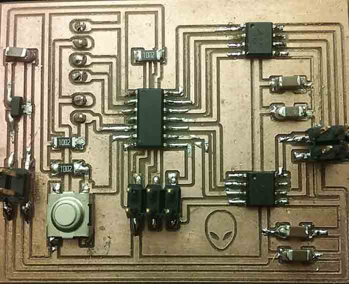
Soldering
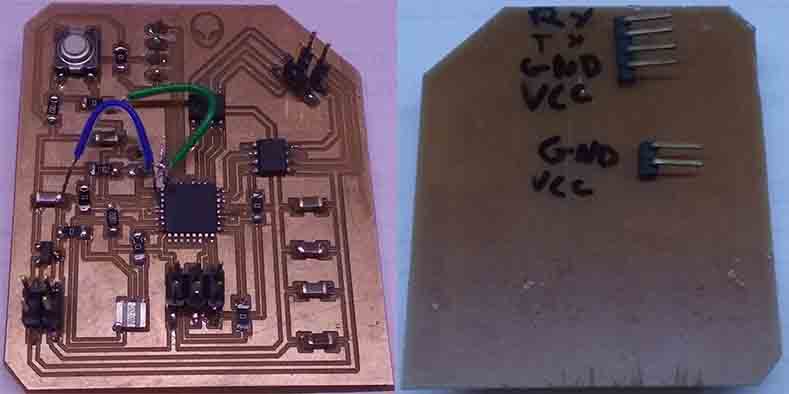
In general this process was easier than before at the beginning but when I finish and connect to my programmer the output micro-controller start to overheating so I had to use the multimeter to check if all the connections were ok, I realized that one capacitor was making contact with something that should not as well as some legs of my micro-controller. After debugging that errors my output micro-controller stop overheating.
Programing
Arduino.
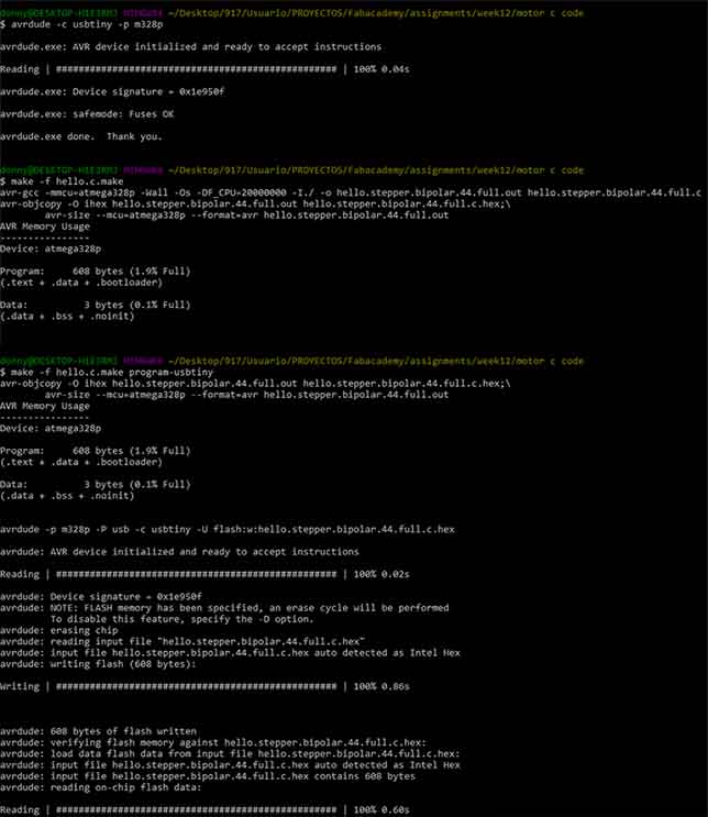
C-Code
- avrdude -c usbtiny -p m328p
- make -f hello.c.make
- make -f hello.c.make program-usbtiny
You can download the files:
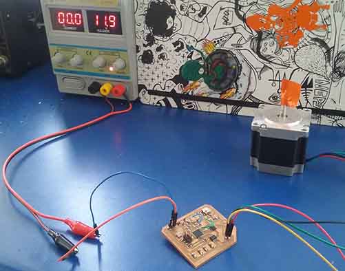
Testing the stepper motor.
Power consumption:
To feed my board with the desired energy to move the stepper motor I need 12 volts and for that I had to use a power supply, and for that I had to adjust the knobs of the positive energy (red) and the negative energy (black) until the display mark 12 volts, It was a little difficult to get exactly that measure so I just achieve 11.9 volts.
Problem:
The stepper motor didn't respond and also I the microcontroller is overheating slowly.
Debugging:
Goal: taking advantage of the creation of a new board for the week14 "networking and communications" I design a board that include both devices the stepper motor and a bluetooth and save time killing two birds with one shot.
Design: This time I decided to take as reference the hello.stepper.bipolar.44.board and also the board of Stéphane Muller who can achieve move the stepper motor in the regional review.
This time I'm using a ATtiny44A
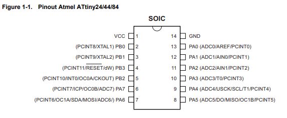 PIN configuration.
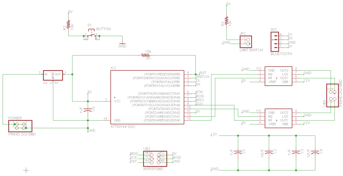
Schematic:
- Add all the components.
- Create the connections between the components and the microcontroller.
- Run the error checker and correct them.
- Switch to the board view.
 Schematic
Board:This time I spend a lot of time making sure everything is all right and doing a good design.
 Board
Board
You can download the files:
PNG:
 Traces
 Cut
Cut
MODS: In the milling process I use a new milling cutter tool so I did two tests the fist one with a cut depth=0.06 and the second one with a cut depth=0.1 this two PCBs help me to set up the machine PCB for the machine design week where I use a cut depth=0.05 and the result was really good.
 Traces / Cut
 PCB
PCB
You can download the files:
Solder: This part take me all the day soldering the components more difficut to solder were the drivers because the bottom side need to be solder to the ground for that I use a heat gun and also the regulator because of the size.
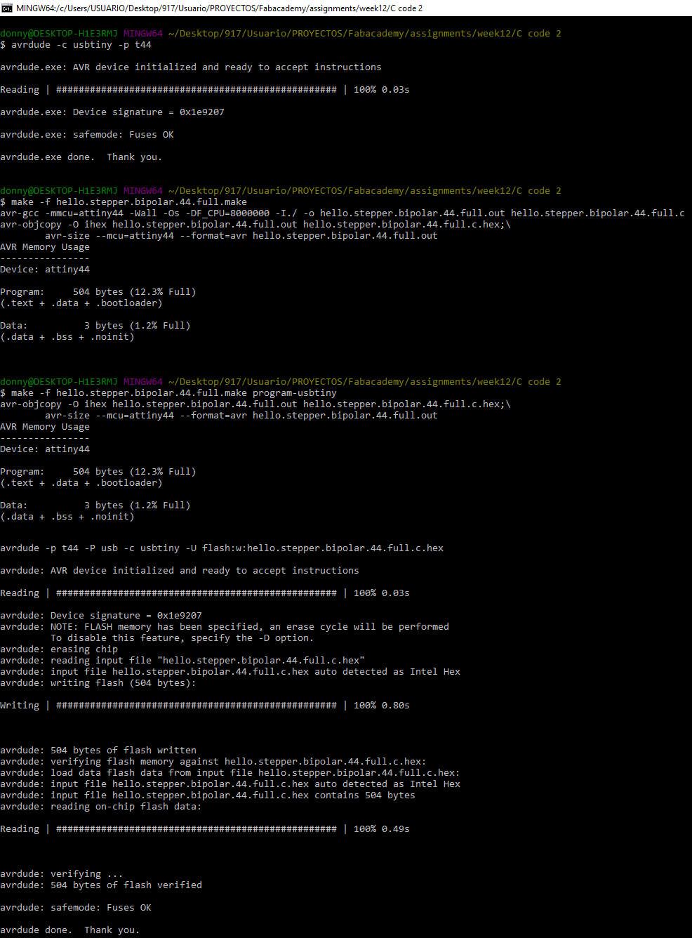
Programing with the hello stepper bipolar 44 code: For this attempt I'm using the same code of Neil example and the board programed without any problem.
You can download the files:
Testing the stepper motor
I connect the stepper motor to my board and also the power supply and the voltage go down and the current go up I try for three times, the first one I see a sparkle and the last one a little smoke appear so I disconnect intermediately. I try to figure what's happening and connect my programmer to upload another code and I realized that the 5V regulator was overheating when it was connected to my PC trough the programmer.
After that I desolder the regulator and test if there are any wrong connection or even if VCC was connected to GND or if any component wast wrong connected after that I programed my board with another code.
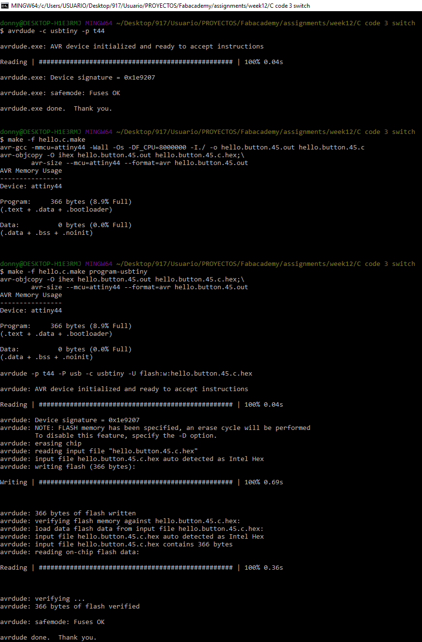
Programing with the hello button code: I change some parts of the code that I use for the input devices week to test if the microprocessor is still working and after that I upload it. After that I solder again the regulator and is still overheating. Just to know if the code was working correctly I opened the arduino software and also the serial monitor and when I star to push the switch give us the desired answer.
You can download the files:
Finding the problem
After that I test the connections in the board and I realized that one driver burned because the motor that I was using is 2.8 Amps/phase and it wasn't the right one to check that I had to review the A4952 driver data sheet and I found that the output currents is 2A so I desolder the driver and solder a new one and change the motor to a KL23H241 that manage 1.0 amps current.
When my board is connected to my PC through my programmer the regulator is still overheating but when I connect directly to the power supply doesn't overheat.
Finally I fix the problem with my board and now it's working! :D
Button + Stepper motor + limit switch + bluetooth
I started searching in the fabacademy browser about stepper motors an I find Yue Siew Chin who says that was difficult to understand whats behind the C code he as same as me try to add a button to turn on the stepper motor he also is using the hello.button.45.c and the hello.stepper.bipolar.44.full.c to reach his objective and here is his code.
What I did is to understand Neil code and after that understand what is Yue doing then using his codes as reference I edit it to fit in to my project necessities.
Also I try to connect my limit switch attached to other board through bluetooth but at the first attempts didn't work. To fix that I add part of the hello.ftdi.44.echo.interrupt.c code.
I have to say tank you to Alex who is guiding us with the electronics and codding I learn a lot doing this in C code.
I did the next work flow:
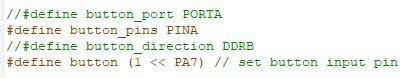
Switch:
- Define the switch pin

Button:
- define the button pins
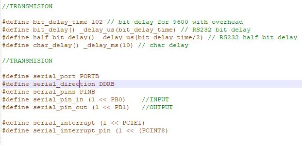
Bluetooth:
- Define the serial ports:
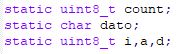
- Define variables: I add one more variable called "j" for the bluetooth message. "i" = PWM counter, "a" activate the motor and "d" is the direction.
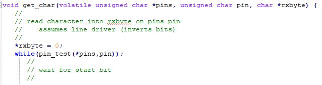
- To send characters in txchar on port pin.
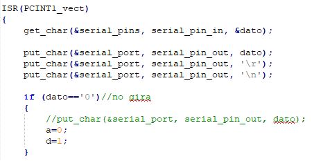
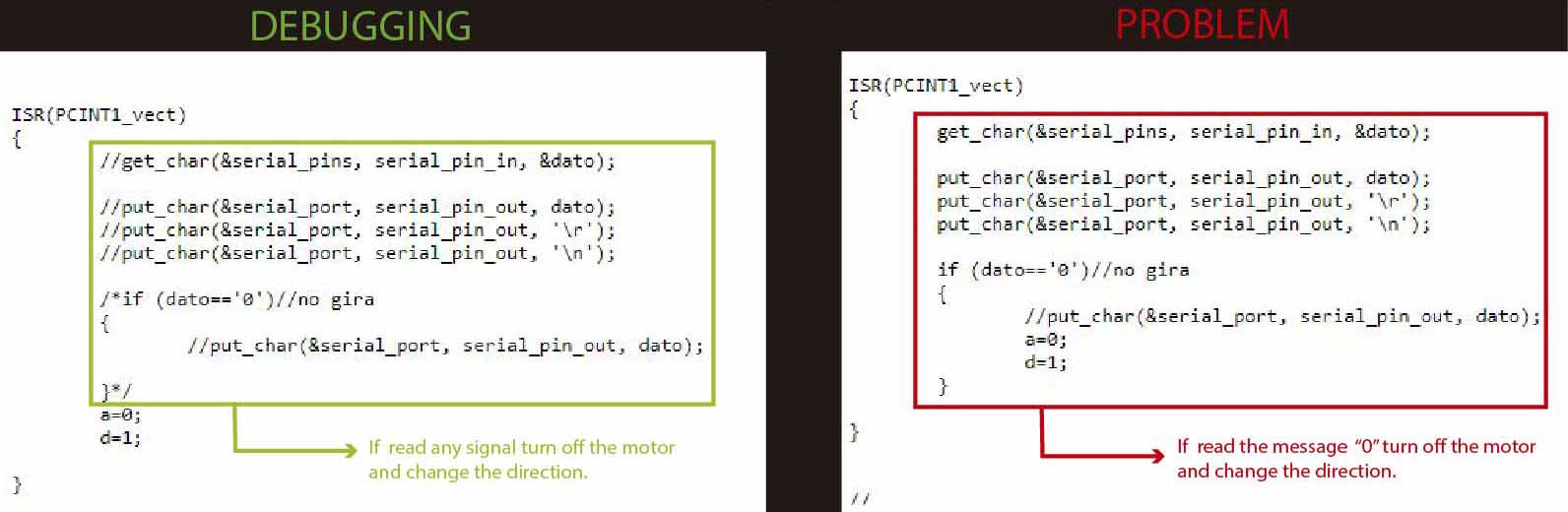
- Interrupt: to interrupt the main code if read the message "0" stop the motor and change the direction.
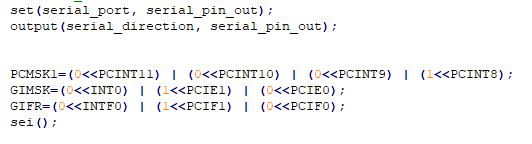
- Set up pin change interrupt on input pin
Main Void loop:
- In the motor board if the button is pushed send a message "1", If the limit switch is push send the message "0".
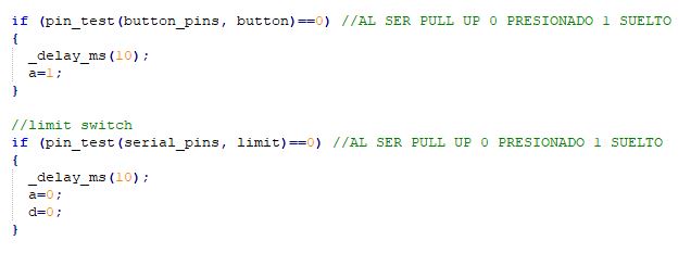
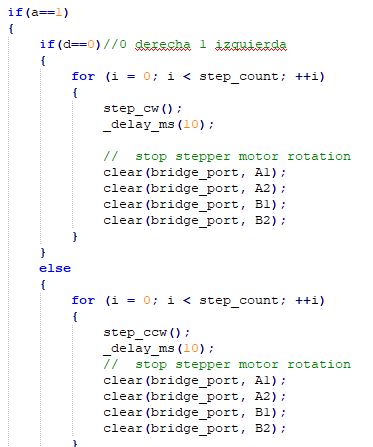
- If the message is "1" the motor star to move for the left if the message is "0" the motor stop and change it's direction.
You can download the file:
Problem:
The code is doing what I want but at the end when I send the message from the bluetooth the motor stop but the corrent go down to 7. That's a problem because I need the voltage to 12 to keep with the movement in the other direction.
Debugging
I found the problem of the voltage get low is because my motor need only 10 volts instead of 12 after I try with 10 volts the problem of the voltage that go down fixed and also I had to make some changes in my c-code to fix the problem about the motor doesn't start after the limit switch push.
Instead of reading the message "0" now is reading any signal from the bluetooth:
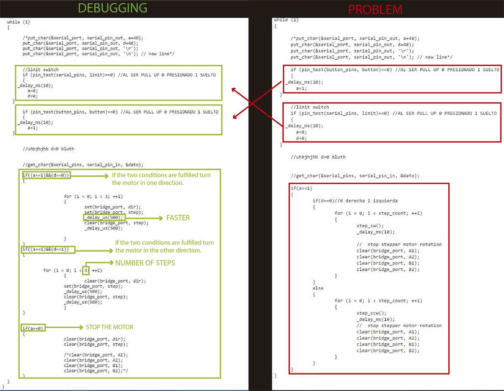
In the main loop I change the order of the limit switch and button and now I understand that the order matter and it alters the result. Also I had to simplify the main loop giving it a better order. Finally I increase the speed and the number of steps this to give more power when need to pull the retractable system and release from the limit switch.
Check the video!
You can download the file:
Easy driver
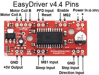
After I can't achieve move the stepper motor the first time I start searching for another options and I found this device called Easy Driver and the name caught my attention. It's important to consider that this device is not at the Fab inventory so I buy this driver for 6.00 $ and I started googleing about it and I found this link with a lot information and some examples of code. And data sheet. I did the next work flow:
- Solder the pins.
- Connect the easy driver and the ArduinoUNO to a bread board.
- Connect the motor's four wires to the Easy Driver (note the proper coil connections), connect a power supply of 12V is to the Power In pins, and connect the Arduino's GND, pin 8 and pin 9 to the Easy Driver.
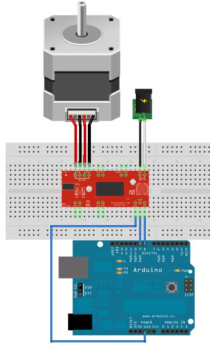
- Then load this sketch and run it on your Arduino
- Pin 8 and 9 as outputs. It sets them both low to begin with.
- When in the main loop, it simply toggles pin 9 high and low, waiting 1ms between toggles.
- We use pin 9 as the STEP control and pin 8 as the DIRECTION control to the Easy Driver.
- Since we are not pulling either MS1 or MS2 low on the Easy Driver low, the Easy Driver will default to 1/8th microstep mode. That means that each time the "digitalWrite(9, HIGH);" call is executed, the stepper motor will move 1/8th of a full step. So if your motor is 1.8 degrees per step, there will be 200 full steps per revolution, or 1600 microsteps per revolution.
- The STEP signal 1ms high and 1ms low, each complete pulse will take 2ms of time. Since there are 1000ms in 1 second, then 1000/2 = 500 microsteps/second..
- Slower: We change the delay(); lines to have longer delays. If you use delay(10); for both, the you'll move at 50 microsteps/second.
- Faster: We can change the delay() calls to delayMicroseconds(100); calls and then each delay would be 100 microseconds (or us), so the motor would be driven at 5000 microsteps/second.
You can download the file:
Conclusion:
Using zero resistances as bridges to connect the components wasn't a good solution because at the moment I want to discover where was the error I got confused.
Use cables as bridges are a temporal solution to fix any problem in the board but is not the better solution because in my case find which one is the problem was very difficult.
It's very important to review the current that a motor consume also the current the drivers support and always review the datasheet and the product details.
Goal: taking advantage of the creation of a new board for the week14 "networking and communications" I design a board that include both devices the stepper motor and a bluetooth and save time killing two birds with one shot.
Design: This time I decided to take as reference the hello.stepper.bipolar.44.board and also the board of Stéphane Muller who can achieve move the stepper motor in the regional review.
This time I'm using a ATtiny44A
Schematic:
- Add all the components.
- Create the connections between the components and the microcontroller.
- Run the error checker and correct them.
- Switch to the board view.
Board:This time I spend a lot of time making sure everything is all right and doing a good design.
You can download the files:
PNG:
MODS: In the milling process I use a new milling cutter tool so I did two tests the fist one with a cut depth=0.06 and the second one with a cut depth=0.1 this two PCBs help me to set up the machine PCB for the machine design week where I use a cut depth=0.05 and the result was really good.
You can download the files:
Solder: This part take me all the day soldering the components more difficut to solder were the drivers because the bottom side need to be solder to the ground for that I use a heat gun and also the regulator because of the size.
Programing with the hello stepper bipolar 44 code: For this attempt I'm using the same code of Neil example and the board programed without any problem.
You can download the files:
Testing the stepper motor
I connect the stepper motor to my board and also the power supply and the voltage go down and the current go up I try for three times, the first one I see a sparkle and the last one a little smoke appear so I disconnect intermediately. I try to figure what's happening and connect my programmer to upload another code and I realized that the 5V regulator was overheating when it was connected to my PC trough the programmer.
After that I desolder the regulator and test if there are any wrong connection or even if VCC was connected to GND or if any component wast wrong connected after that I programed my board with another code.
Programing with the hello button code: I change some parts of the code that I use for the input devices week to test if the microprocessor is still working and after that I upload it. After that I solder again the regulator and is still overheating. Just to know if the code was working correctly I opened the arduino software and also the serial monitor and when I star to push the switch give us the desired answer.
You can download the files:
Finding the problem
After that I test the connections in the board and I realized that one driver burned because the motor that I was using is 2.8 Amps/phase and it wasn't the right one to check that I had to review the A4952 driver data sheet and I found that the output currents is 2A so I desolder the driver and solder a new one and change the motor to a KL23H241 that manage 1.0 amps current.
When my board is connected to my PC through my programmer the regulator is still overheating but when I connect directly to the power supply doesn't overheat.
Finally I fix the problem with my board and now it's working! :D
Button + Stepper motor + limit switch + bluetooth
I started searching in the fabacademy browser about stepper motors an I find Yue Siew Chin who says that was difficult to understand whats behind the C code he as same as me try to add a button to turn on the stepper motor he also is using the hello.button.45.c and the hello.stepper.bipolar.44.full.c to reach his objective and here is his code.
What I did is to understand Neil code and after that understand what is Yue doing then using his codes as reference I edit it to fit in to my project necessities.
Also I try to connect my limit switch attached to other board through bluetooth but at the first attempts didn't work. To fix that I add part of the hello.ftdi.44.echo.interrupt.c code.
I have to say tank you to Alex who is guiding us with the electronics and codding I learn a lot doing this in C code.
I did the next work flow:
- Define the switch pin
Switch:
- define the button pins
Button:
- Define the serial ports:
- Define variables: I add one more variable called "j" for the bluetooth message. "i" = PWM counter, "a" activate the motor and "d" is the direction.
- To send characters in txchar on port pin.
- Interrupt: to interrupt the main code if read the message "0" stop the motor and change the direction.
- Set up pin change interrupt on input pin
Bluetooth:
- In the motor board if the button is pushed send a message "1", If the limit switch is push send the message "0".
- If the message is "1" the motor star to move for the left if the message is "0" the motor stop and change it's direction.
- Solder the pins.
- Connect the easy driver and the ArduinoUNO to a bread board.
- Connect the motor's four wires to the Easy Driver (note the proper coil connections), connect a power supply of 12V is to the Power In pins, and connect the Arduino's GND, pin 8 and pin 9 to the Easy Driver.
- Then load this sketch and run it on your Arduino
- Pin 8 and 9 as outputs. It sets them both low to begin with.
- When in the main loop, it simply toggles pin 9 high and low, waiting 1ms between toggles.
- We use pin 9 as the STEP control and pin 8 as the DIRECTION control to the Easy Driver.
- Since we are not pulling either MS1 or MS2 low on the Easy Driver low, the Easy Driver will default to 1/8th microstep mode. That means that each time the "digitalWrite(9, HIGH);" call is executed, the stepper motor will move 1/8th of a full step. So if your motor is 1.8 degrees per step, there will be 200 full steps per revolution, or 1600 microsteps per revolution.
- The STEP signal 1ms high and 1ms low, each complete pulse will take 2ms of time. Since there are 1000ms in 1 second, then 1000/2 = 500 microsteps/second..
- Slower: We change the delay(); lines to have longer delays. If you use delay(10); for both, the you'll move at 50 microsteps/second.
- Faster: We can change the delay() calls to delayMicroseconds(100); calls and then each delay would be 100 microseconds (or us), so the motor would be driven at 5000 microsteps/second.
Main Void loop:
You can download the file:
Problem:
The code is doing what I want but at the end when I send the message from the bluetooth the motor stop but the corrent go down to 7. That's a problem because I need the voltage to 12 to keep with the movement in the other direction.
Debugging
I found the problem of the voltage get low is because my motor need only 10 volts instead of 12 after I try with 10 volts the problem of the voltage that go down fixed and also I had to make some changes in my c-code to fix the problem about the motor doesn't start after the limit switch push.
Instead of reading the message "0" now is reading any signal from the bluetooth:
In the main loop I change the order of the limit switch and button and now I understand that the order matter and it alters the result. Also I had to simplify the main loop giving it a better order. Finally I increase the speed and the number of steps this to give more power when need to pull the retractable system and release from the limit switch.
Check the video!
You can download the file:
Easy driver
After I can't achieve move the stepper motor the first time I start searching for another options and I found this device called Easy Driver and the name caught my attention. It's important to consider that this device is not at the Fab inventory so I buy this driver for 6.00 $ and I started googleing about it and I found this link with a lot information and some examples of code. And data sheet. I did the next work flow:
You can download the file:
Conclusion:
Using zero resistances as bridges to connect the components wasn't a good solution because at the moment I want to discover where was the error I got confused.
Use cables as bridges are a temporal solution to fix any problem in the board but is not the better solution because in my case find which one is the problem was very difficult.
It's very important to review the current that a motor consume also the current the drivers support and always review the datasheet and the product details.