Week 08
Computer-Controlled Machining
Assignment:
- Group assignment
Test runout, alignment, speeds, feeds, and toolpaths for your machine.
- Individual assignments
Make (design+mill+assemble) something big.
- Learning outcomes:
Demonstrate 2D design development for CNC production. Describe workflows for CNC production. - Have you:
Explained how you made your files for machining (2D or 3D). Shown how you made something BIG (setting up the machine, using fixings, testing joints, adjusting feeds and speeds, depth of cut etc). Described problems and how you fixed them. Included your design files and 'hero shot' photos of final object.
Tests
Run out:In the holes that I created the diameter were a little bit larger than the digital dimensions.
Alignment:Considering the press-fit that I machine and after assemble it I could say the alignment is well calibrated but I think that always the dimension of the digital file differ from the reality.
Speeds and Feeds:The speed that we use for our CNC machine usually work at 16000 rpm and the feeds vary depending of the material.
Toolpaths:We can configure different tool paths depending the job that we want to make.
For our personal projects in this assignment we use wood of different thickness according to the need of each one, Jorge use 15 mm MDF, Ale and me are using 5 mm MDF. So first we did the parameter test for 15mm MDF thickness, after that we did the same test for 5 mm MDF. We started downloading Guillermo Guerra file Test to analyze, understand and after modify and create our own files.
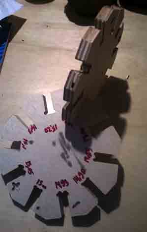
15 mm MDF test:
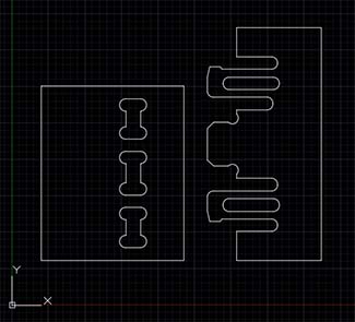
For this test we put different types of "t-bones" and we increase and reduce the size of the pockets in a factor of 0.05 mm starting from a base of 15 mm the thickness of the material. We did this because we want to know the tolerance and the behavior of the material as a press-fit structure.
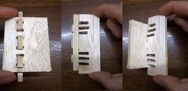
The result of the test was:
- Smaller pockets dimensions to 15mm: it was almost impossible assemble them because the dimension was smaller than the thickness material.
- 15 mm pockets (material thickness): it was difficult assemble one part with the other, we had to put a little pressure and when we want to separate it was much more difficult using our hands, we had to use a rubber hammer to do that.
- Bigger pockets dimensions to 15 mm: as the dimension of the pockets increased, the assemble and disassemble the parts was easier.
- T-bones: are used to allow the milling cutter generate 90 degrees inside the pockets. We use a two flute milling cutter of 4 mm so the diameter of our t-bone has to be more than 4.1 mm. T-bones can be located in different ways according to the needs of the design.
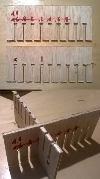
5 mm MDF kerf test
My friend Ale was using the same material as me so she did a comb shape kerf test like we did in the laser cut assignment. The results of this was 5.2 mm pocket was the best size to assemble and dissemble so we figure the kerf index was 0.1 mm to each side.
5 mm MDF test:
I did a similar test to know the tolerance and the behavior of the material I want to use for my final project. In this assignment I want to test my design and the material for the shelter structure.
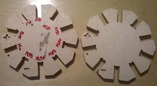
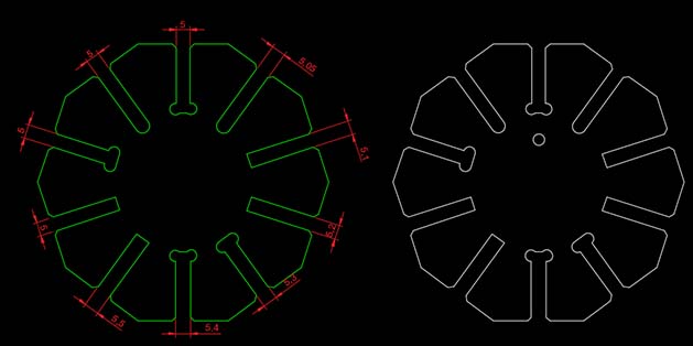
For my test I draw a pentagon using Autocad and then I add the pockets in each side. I choose to put four pockets of 5 mm with different t-bones to know if the location of them affect the press-fit system. Also I increase the dimension in a factor of 0.05 mm and 0.1 mm.
Autocad
I use Autocad to create a decagon and then to edit the shape and add the pockets with different dimensions and the t-bones and finally join the different polylines to make one shape.
You can download the file:
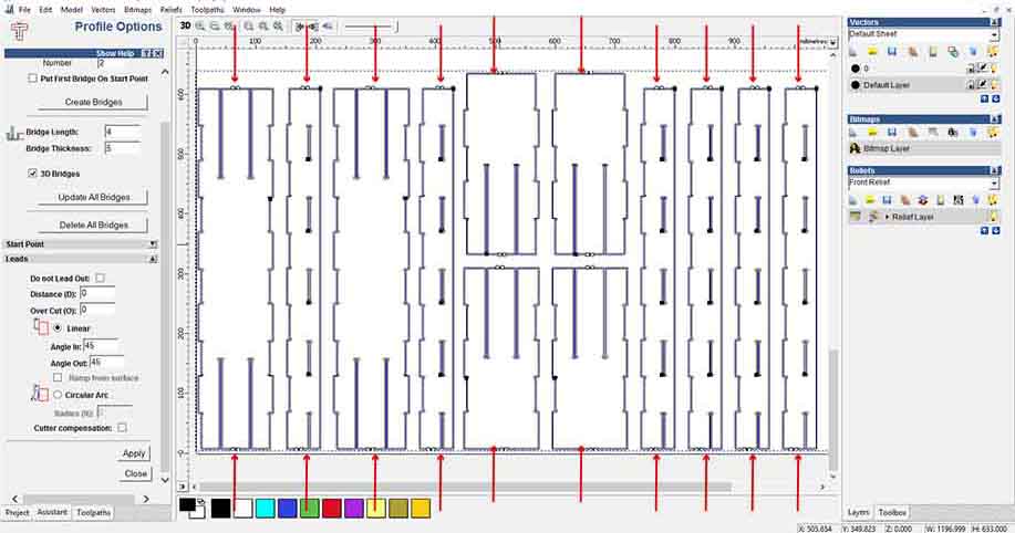
ArtCam
Autodesk ArtCAM is a single solution for designing and making in the woodworking industry has been discontinued with no planned future releases or updates. We are using a 2008 version that was previously installed on a PC.
- Open ArtCam.
- Create a new model.
- Size for a new model (Heigh Y: 2440 mm, width 1200 mm).
- From the vector menu, select import your DXF or Illustrator 3 file.
- Locate near the point (zero left lower corner).
- Toolpaths:
- Start Depht: 0
- Finish Depth: 5
- Tolerance: 0.01
- Safe Z: 25
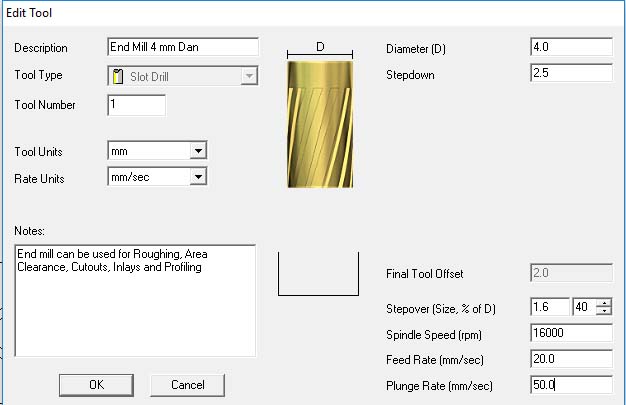
- Profile tool: I have to Create a new tool for my 4 mm milling cutter.
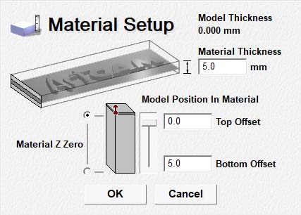
- Add material: thickness 5 mm and adjust the Z zero point to top.
- In the work screen select the files you want to cut.
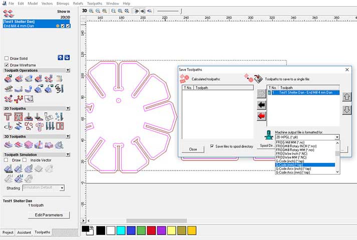
- Click the button "Calculate now".
- Save toolpaths: choose the toolpath and select "G-Code (mm) (*.tap)"
- The G code is READY!
You can download the files:
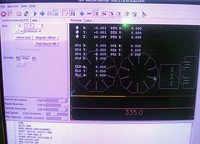
LinuxCNC
LinuxCNC controls CNC machines. It can drive milling machines, lathes, 3d printers, laser cutters, plasma cutters, robot arms, hexapods, and more.
In our fablab we are using this software and is pretty easy to use I follow the next steps:
- Upload the g-code file created in Artcam.
- Define zero home for the X, Y (they had to be defined in the left bottom side of the material) and Z axes, one way to define the last one is start running the spindle and get down slowly until barely touch the wood.
- We can check the path that our spindle is following to know if there are any crash or error with the position of the pieces.
- Start the process step by step until the spindle engine is ready to cut.
- Now we can start the whole process and pause it or stop it if it was necessary.
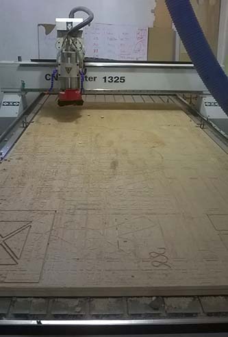
CNC Router 1325
For me this machine is pretty easy to handle and very useful. Some of the characteristics of our fablab CNC machine are:
- Water cooling spindle.
- water pump
- Working area 1220 mm X 2440 mm.
- Sensors located in the X, Y and Z axes.
- Dust collector work with 220v
- Cooling system
- Control panel.
- Transformer for the CNC.
Safety:
It's very important to remember the safety precautions:
- Never wear loose clothing, remove jewelry like necklaces, bracelets, watches, rings, etc.
- Tie long hair into a ponytail.
- Wear eye protection.
- Before beginning work on a machine, ensure that all machine controls and work surfaces are clear of dust, debris, dirt, grease or tools.
- Don't be distracted while you operate a machine. And always do it in company of another person in case of emergency
- Handle carefully the milling cutters.
- Stay away of the right side of the machine when it's working because the space is limited.
- Use ear protectors.
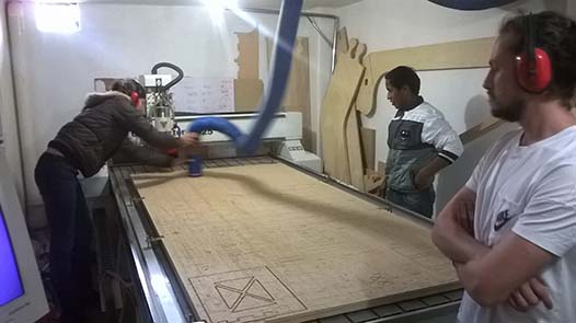
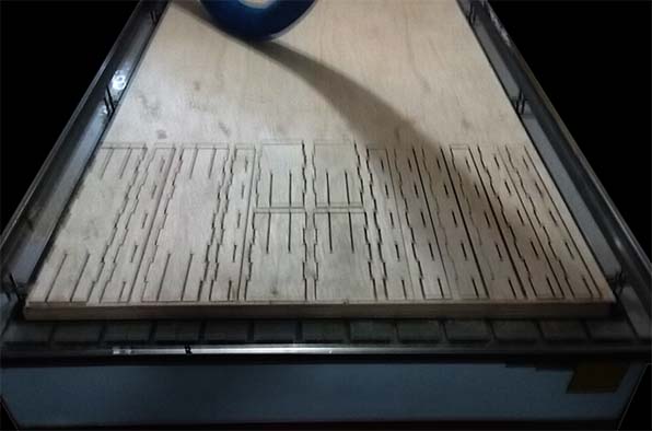
Machining
- Turn on the ignition switch.
- Turn on the control panel.
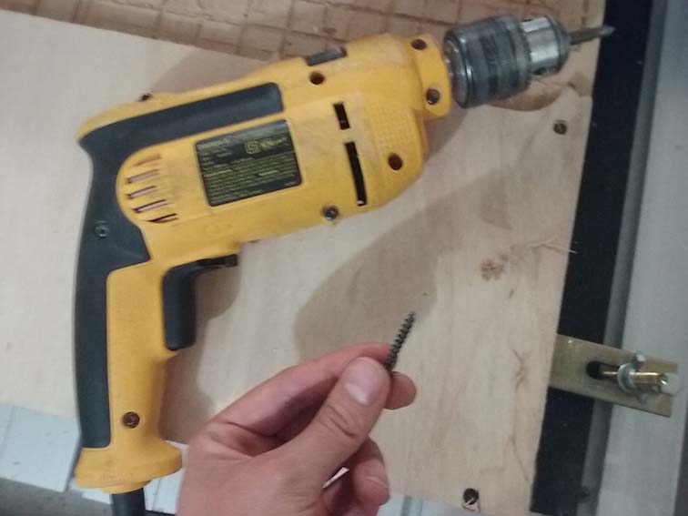
- Place the material on the sacrificial layer and secure it with screws at least in four points.
- Adjust the desired milling cuter using the right tools.
- Open Linux CNC.
- Turn on the extractor.
Computer controlled machining
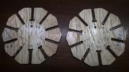
The result of the test was:
- T-bones: I figure that when I work in materials with little thickness and because of the size of the milling cutter like my material of 5 mm thickness and milling cutter of 4 mm the types of location of the t-bones was reduced to one of the size of the material or two at the left and right edges. Also for me the the location of the t-bones affect the press fit system, for example when I was assembling the pockets with one t-bone with the diameter of the material was easier to dissemble compared to the two t-bones located at the sides.
- 5 mm pockets: the first assemble was a little hard but when it was disassembled and then put together many times the assemble is easier and the parts still fit well.
- Bigger dimensions than 5mm: was easier to assemble disassemble.
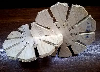
Comment: The result of the test has a lot burr because I didn't secure the piece with bridges or a screws so the pieces move when it was being cut and also the same error happened to me the first time I cut in the section make something big It wasn't a problem of the speed or feed because after I cut my pieces securing it them and didn't have this burr. So Is very important to secure our piece with bridges or also with screw but if we choose to do the second way we have to be very careful and check that the screws don't collapse with the cutter.
FINAL PROJECT
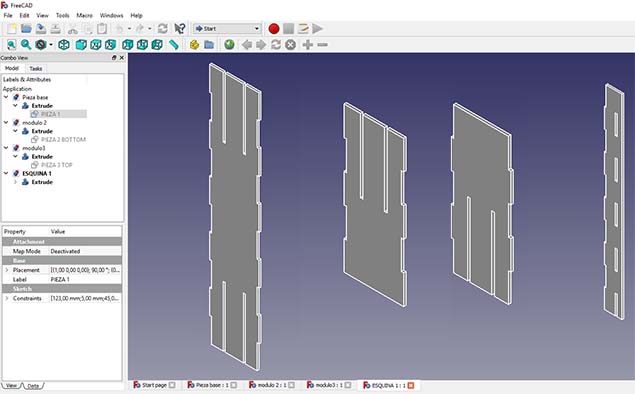
Freecad
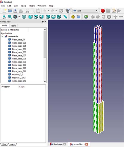
I continue working in the files that I created for the press-fit kit because they were parametric and that make easily to change the thickness of the material from 4mm that belong to cardboard to 5mm triplex also the others dimensions. Also I create an assembly of my pieces using the assembly2 workbench.
You can download the files:
Freecad Path workbench
I found this tutorial where they show the creation of a Path Job from a 3D Model, generating dialect-correct G-Code for a target CNC mill. So I try to generate my gcode doing the next process:
- Open the 3D model.
- Switch to Path workbench.
- Selecting the extrusion create a Patch Job object and set up.
- Job output: select the output file path and the Processor linuxcnc
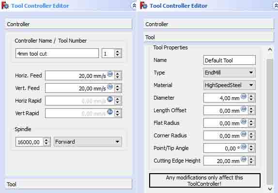
- Job tools: Edit the default tool
- Horiz. Feed: 20 mm/s
- Vert. Feed: 20 mm/s
- Spindle: 160000
- Type: End mill
- Diameter: 4mm
- Job workplan: sequence of Job Operations.
- Path operations
- Contour: review and ok.
- Verify the paths
- Inspect tool
- Path simulator
- Select the Job object in the tree
- Select the Path Postprocessing
- Inspect before processing.
- Select the job and export to gcode-linuxcncn procesor
You can download the file:
Clip Test
I found this amazing digital joints and a machine that use clip joints so I use the files as a reference to create a clip that help me secure my pieces, for that I made some tests, the first one and the second one using 4 mm MDF and the third one with 5mm Triplex.
It was very difficult to put it together but at the end I achieved it. I think if I include this clip in my project maybe could be much more difficult to assembly all the parts, so I decide to experiment first how the material work without the clips and if it's necessary I can add to the design.
You can download the file:
Autocad
After I had my parametric files in Freecad I exported to DXF and open it in Autocad to make some tests of an idea that I had. I change to this software to safe time because I already know it and I work faster on it but in the future when I have more time I will use Freecad.
The idea is to make more secure the assemblies adding some clips, but I realized that could be more difficult assemble the parts taking into account that there are to many pieces.
If this is really necessary I'll add this to my design but first I want to try if works well without the clips.
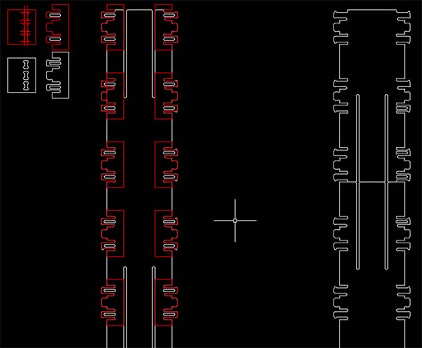
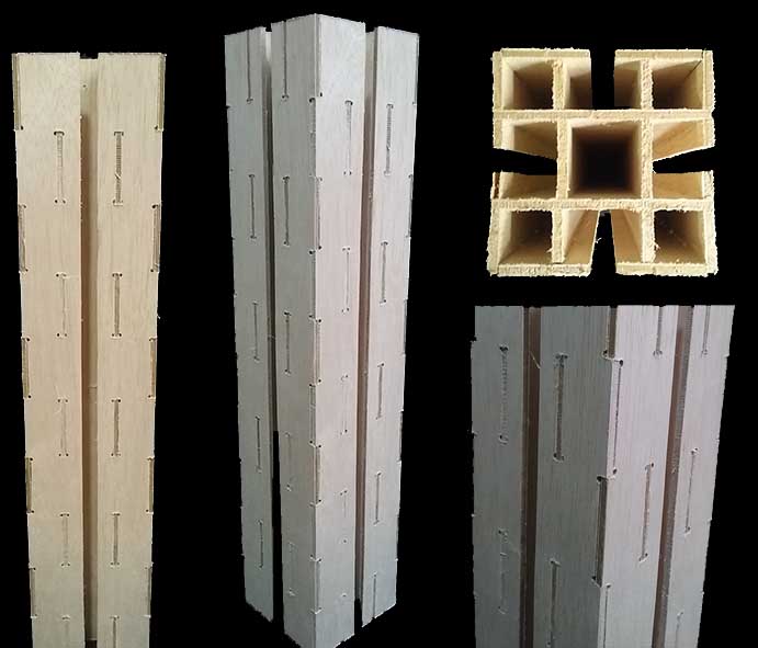
Make something big
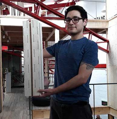
For this assignment I want to machining a part of the main structure of my final project to know how the material behaves once assembled this part could be a beam or a column, the dimensions of this part are: height 60 cm, length 12.3 cm and width 12.3 cm. It's conformed of 14 pieces.
I did the same steps that I describe before using ArtCam to create the G-Code and the same steps to open it using LinuxCNC and run the CNC machine.
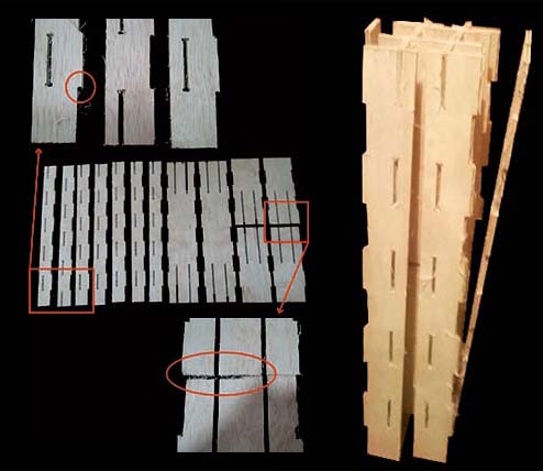
Error
At my first attempt the result of the machining was pretty bad, it was very difficult to assemble and when I check what's going wrong I observe the next errors:
- The location of the T-bones at the corners wasn't the right one for my design.
- The holes of the corner pieces were displaced.
- In the machining process the pieces where to close to each other so there was not place to secure one side of the next piece.
- I didn't create bridges to secure the pieces.
- Because the pieces were loose the cut went wrong.
- The bed of the CNC machine isn't uniform so in some pieces the the machine don't cut the desired thickness.
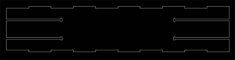
Debugging
In my second attempt the result was the desired. This are the corrections that I did:
- Locate the T-bones at the end of the pockets.
- Correct the holes of the corner pieces to match with the pins of the other pieces.
- Leave more space for separation between pieces.
- Create two bridges per piece to secure it.
- Define the Z axes a little bit lower. Because of this the bridges that I create where cut at the second pass, I realized that I could make the cut just in one pass to save time.
You can download the files:
Watch the evolution of my prototype in this video:
Conclusions:
Its very important to make sure about your design and the possibilities that could go wrong when you machine, for that review carefully your files, make small test and don't machine a big file without reviewing or testing it first.
Secure the pieces that you are going to cut.
Think about the time that will take the machining process.
The most important thing is the safety make sure to follow the correct work flow.