Week 10
Molding and Casting
Link to the class content- Group assignment
Review the safety data sheets for each of your molding and casting materials.- Make and compare test casts with each of them
- Individual assignments
Design a 3D mould around the stock and tooling that you'll be using, machine it, and use it to cast parts.
- Learning outcomes:
Design appropriate objects within the limitations of 3 axis machining. Demonstrate workflows used in mould design, construction and casting. - Have you:
Explained how you designed your 3D mold and created your rough and finish toolpaths for machining. Shown how you made your mold and cast the parts. Described problems and how you fixed them. Included your design files and "hero shot" photos of the mould and the final object.
Group assignment

Safety
General precautions:
- Work in a space with good ventilation.
- Safety glasses (Causes serious eye irritation).
- Protective Gloves (Causes skin irritation).
- Mask (Avoid breathing dust/fume/gas/mist/vapors/spray).
Work flow:
- Review safety the data sheet.
- Prepare the materials and the work area.
- Simulate work process to know step by step what you are going to do and calculate estimated time it could take to ensure the materials don't get dry.
XTC-3D

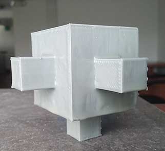
We did a team work to cast the molds of Ale and Jorge using XTC-3D, I use it to cover a 3D print scale prototype of the vertex joints of my final project. We did the next process:
- Review the safety data sheet.
- Put on the mask, gloves and safety glasses.
- Simulate the work flow to know what each one has to do and to know the time it could take us.
- Ale was in charge of measure the part A and Jorge the B, I was in charge to mix the two parts and it has to be done slowly without generating bubbles using the square edge of mixing stick to bring material off of the sides and bottom of container and blend.
- After that they cast their molds and I spread over my 3d print piece using a disposable chip brush.
The result was not the desired, I realized that I spread a lot material and I only need a thinnest coating but the experience was really cool.
MOLD STAR 30
Liquid rubber for pouring over original models, sculpture pieces and more
Liquid rubber product for making flaxible molds process:
- Combine equal amounts of liquid parts A and B.
- Mix liquid rubber contents thoroughly.
- Pour over prepared model and let it cure to a solid, flexible rubber mold.
- Demold to reveal mold cavity.
Liquid plastic products for making fast plastic pieces process:
- Combine equal amounts of liquid parts A and B.
- Mix liquid plastic contents thoroughly.
- Pour into rubber mold cavity and let cure.
- Demold solid plastic castings in minutes. Cast and again!

Comparison
- Mold star and XTC-3D have a data sheet included in the package and very good information in the Internet in contrast to the silicone rubber and the catalyst that we can found locally.
- Mixing the A and B chemical components generates heat in contrast with concrete that does not.
- Concrete takes much more time to cure compared to XTC-3d
- Concrete is less dangerous than XTC-3D, but you should also take precautions.

Design
Final project
I choose to create a base for the column that I created for "make something big assignment".
The first idea was to create a pin of 9 centimeters that can be inserted in the hole of the column and secure it to the ground, but after discuss the idea with my instructor I realized that I am limited for the dimensions of the milling cutter (3 cm length) also for the material of the mold (3 mm MDF ), at the end the high of my piece is 3 centimeters and the length 20 X 20 centimeters.

Freecad
I decided to use Freecad because I have been working in this software and I think the chance of parameterize is really use full. For that I follow the next steps:
- Measure the real dimensions of the assembled column.
- In a new sketch I create the 2D parametric drawing using the "sketch workbench".
- Then using the "Part workbench" I extrude my 2D sketch to generate a 3D model.
- I selected the upper face of my 3D model to create a new sketch and draw the pins and after to extrude them.
- Again I selected the same upper face and create a new sketch and draw four circles and after that I extrude it negatively to generate a boolean operation to create four holes where the screws will enter.
- With the file ready I use the "mesh workbench" to transform my solid in to a mesh and save it as a STL.


You can download the file:
Fab modules
I open the Link attached in the class content and upload my stl file but when I click on "calculate height map" button any image show in the screen, I continue the process and select the output format G-codes and finally click on "calculate height map" but again nothing happen. The same thing happen to my friends so we decided to change the software.

Fusion360
I fund this really use full tutorial about how get started with CAM. I found the user interface and the process easy to handle and very well documented and the simulation workspace really useful. this is the process that I followed to generate my gcode:
- In Freecad export as STEP file (so that it is easily read as solid).
- Manufacture workspace.
- Create a New Setup and define the origin.
- In Set up define the Orientation: Select Z axis click the upper face also for the x axis and define the origin by selecting stock point.
- In Stock define the mode to Relative size box.
- 3D / Pocket clearing (Roughing)
- Select the tool: 6mm
- Spindle speed: 16000 rpm
- Cutting feedrate: 30 mm/min
- Plunge feedrate: 20 mm/min
- In Geometry Select machining boundary to boundin box.
- In Heights the clearance height 20mm
- In Passes the maximum Roughing stepdown to 5 mm and the step over should be 3 mm.
- 3D / Parallel (Horizontal Finish)
- Select the tool: 4mm (same settings).
- In Geometry Select machining boundary to boundin box.
- In height set the Clearance height form to selection and select the bottom perimeter of the holes.
- I passes the Stepover should be 2mm
- 3D / Parallel (Vertical Finish)
- Same settings as the horizontal finish.
- In geometry Change the X axis tool orientation selecting the other face and flip the axis.
- Simulate
- Check the Stock to visualize the subtractive process.

Gcode:
- Post process window
- Select the gcode type: linuxCNC
- Post
You can download the file:
Artcam
I already use this software for the week 08 I find it really interesting and easy to use. This is the processes I follow to create my G codes:
At the first attempt I created my files with a work area of 30 X 30 cm but my final piece just has 20 X 20 cm, I realized that the cut was to large, so I had to create new files changing my work area to 20 x 20 cm.


You can download the file:
Roughing

- Create a new model and set up the dimensions of the work area (20 X 20 cm).
- Change to the 3D view and in the reliefs menu select import 3D model, center the model and click on paste.
- In toolpaths, select Z level roughing, and select the roughing tool of 6 mm.
- Diameter 6mm
- Stepdown 4 (to make the process quickly)
- Stepover 50%
- Spindle Speed 16000
- Feed Rate 20
- Plunge Rate 30
- Material set up
- Material thickness: 30 mm
- Material zero: top offset 0.0 mm
- Machine safe Z: 20 mm
- Name: roughing 20X20
- Calculate now
- Save Toolpath as G-Code (mm) (*.tap)


You can download the file:
Horizontal finish
- Machine Relief
- Select Roughing tool 4 mm
- Diameter 4mm
- Stepdown 4
- Stepover 30%
- Spindle Speed 16000
- Feed Rate 20
- Plunge Rate 8 (make the milling cuter get down slower)
- Machine safe Z: 20 mm
- Name: finish 1 20X20 mm
- Calculate now
- Save Toolpath as G-Code (mm) (*.tap)

You can download the file:
Vertical finish
- Machine Relief
- Raster angle: 90
- Select Roughing tool 4 mm
- Machine safe Z: 20 mm
- Name: finish 1 20X20 mm
- Calculate now
- Save Toolpath as G-Code (mm) (*.tap)

You can download the file:
Machining
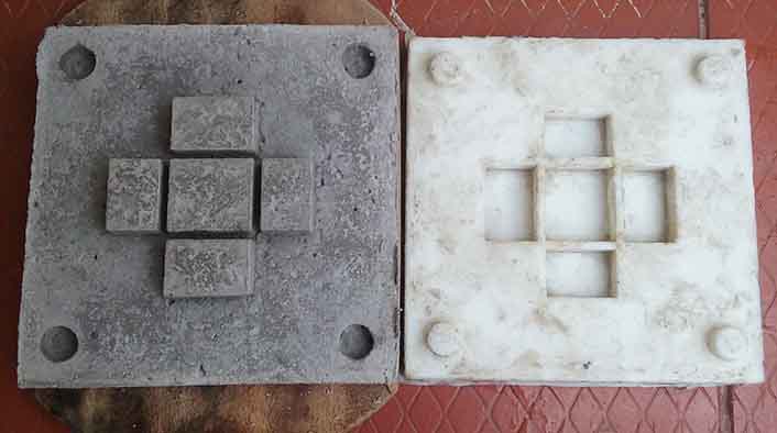
Positive mold
The material I'm using are two layers of MDF, the first one of 20 mm located at the bottom as a base of the second one of 30 mm thickness which will be cut.
The two layers are joined by screws that were carefully located so that it does not crash with the milling cutter, for that I draw by hand a 2D shape with the real dimensions located up and down of my material to know where I locate the screws. After that I secure my material to the work area.
With my files ready I did the next steps:
- Roughing
- Review safety.
- Place the 6 mm flat milling cutter.
- Connect the extractor tube and turn it on.
- Open my file in LinuxCNC.
- Define home X, Y and Z axis.
- Start the process step by step.
- Horizontal Finish
- Once finished the roughing process I take out the milling cutter and put on the 4mm milling cutter.
- Clean the work area
- Open the file in LinuxCNC
- Define Z axis.
- Start the process step by step until the engine is ready and give play the whole process.
- Vertical Finish
- Clean the work area
- Open the file in LinuxCNC
- Define Z axis.
- Start the process step by step until the engine is ready and give play the whole process.
When the milling cutter reach the lowest part of the cut (the four round holes), the metal thread touch the corners of my material, that's because the height the milling cutter was 30 mm and the height of my material is 30 mm too. I was working to the limit which is not recommended.

Error
The milling cutter crash directly with the MDF when it made the separation of 5.3 mm between the central pin and the others, when this happen the milling cutter got loose and continued rotating and we stooped the process. The result was a deeper cut and a cut corner. After that happen for the next separations my instructor advice me to pause the process and run the toolpath slower and this work well.


Debugging
I choose to fill those holes with plasticine because is very easy to handle, is easy to create the shape I want, it's cheap and is easy to find. This solution work well, it joined well to the MDF and didn't give problems with the silicone rubberbecause these materials do not generate too much heat when merged.

Molding
Materials
- Rubber silicone (Component A): It was easy to process because of low viscosity, the cure process was accelerated leaving it in the sun, have to be mixed with the catalyst (component B) and don't need special safety precautions.
- Catalyst (Component B): Thixotropic additive for addition cure silicone has to be mixed with the Component A at between 1 and 3%, depending on how thixotropic you want the silicone to be.
- Vaseline (mold release material): It was easy to handle, it's safe to use and easy to find.

Process of the Negative mold:
- First I have to spread a lot Vaseline in my MDF mold to ensure it was easy to unmold.
- The second step was to put on the mask, vinyl gloves and safety glasses.
- In a plastic glass mix I mixed the component A with the component B, I had to mix slowly to ensure there are no bubbles created in the processes and because of the viscosity was little difficult, after a few minutes the mix started to react and with the help of my instructor I managed to spread it before it dries.
- I let cure for one day.
- For the unmolding process I take advantage of the round holes of the bottom and push the silicone to come out. I realized that the in the two of the four interior walls the mix didn't enter 100% but the rest of the mold it turned out very well.
- I had to assemble a small formwork with some pieces of wood and Scotch tape.
- Then I mixed again the component A and B but this time using just a few material.
- And I let it cure under the sun and it drys really fast. Finally the mold was ready!

Debugging:

Casting
I decided to use concrete for the final object because I want to experiment with this material. I like it very much for it's resistance and beauty.
Materials:
- Safety: the work space has to be ventilated, wear waterproof clothes, when the levels of dust is to high use mask and security glasses.
- Concremix 240: It's a pre-mixed instant concrete reach 245 kg/cm2 resistance at the 28 days.
- Clean water.
- Shovel
- Nails
- Plastic container.
- 5mm Triplex wood for the fromwork.
- WD-40 oil (mold release material): It's a multi-use product used to lubricate, protect metals from rust, etc.
Casting process:
- Nail the formwork aligned with the mold.
- Spread the WD-40 oil.
- In the plastic container mix the concrete and add water until a homogenous mass is generated.
- Pour the contents into the mold.
- Cure the concrete with water.


Unmolding Error:
I didn't be patient and remove the formwork at the next day and the material was not hard yet and because of the negative mold is flexible at the moment I move it little cracks were generated.
After 5 days I remove the object from the mold and the result was pretty bad.

Debugging
I repeat the process taking into account the following aspects:
- The last time I remove the rocks from the mix thinking that it wasn't necessary because of the size of the object, I was wrong! The rocks Allow the mixture to join and let dry faster.
- Wait 7 days at least to remove the mold and the formwork.
- Add a solid base under the flexible mold.
- Add a metal mesh to join the concrete.
- Soon I will show you the hero shot of the final object.

Unmolding
After 13 days I proceed to unmold the piece this time I was very careful when when turning it over the mold and this time the final result was a success, still I have to wait 15 more day until the concrete reach the desired resistance.
Hero Shot
Now that I have one base for the column I need to make tree more for the final project.

3d molding with a 3d shape
I realized with the help of my evaluators that the design for my mold is a 2D shape because can be made in laminar way so to take advantage of this opportunity I want to improve my previously design and make it 3D and also correct some issues that I had with my last design.
PROBLEM:
The problem with my last design is about the dimensions of the holes of the column that I made with the milling process they were different for 1mm or 2 mm to the other columns that I made with the laser cutting process so the column doesn't fit perfectly and when I try to fit my base into the holes the pins break.

FRECAD:
To correct that issues I remove the four pins and just leave the center pin with the right size and also I want to vary the dimension in the bottom to the top for a better assemble with the column and so that my design will be a 3d shape I decided to round the corners and improve the design. For that I did the next work flow:
- Erase the surround pins and correct the dimensions of the central pin.
- Move the holes to 30 mm from the edges.
- Create a NEW SKETCH attached to the upper face with a 20 mm offset in the Z axis 40mm X 40mm.
- In the part workbench create a UTILITY TO LOFT from the 40 X 40 mm square and the other of 45 X 45 mm.
- In the part work bench create a BOOLEAN FRAGMENT to join the central PIN and the base.
- Create a new sketch for the PROFILE (it should be fully constrained) of the rounded corners and a PATH that the profile will follow.
- Change to the PART work bench and select the UTILITY TO SWEPT.
- Select the profile and with CTRL select the path and press ok. I had to do this again in the other side.
- In property change the solid option to true to create a boolean operation.
- Select the two solids and select boolean operation XOR that allows you remove intersection fragments.
- After that I change to a round corners the shape of the central pin.
- Finally export the file as STEP to import it to Fusion 360.


You can download the file:
Fusion 360
For this simulation I use the same configurations that I use before for the previously simulation for the roughing, horizontal and vertical finish tool paths but I add two new ones to contour the central Pin as a finish and also another one for the borders and this are the settings:
- Pin Contour and Border Contour finish.
- 3D Contour
- Select 4 mm ball tool (with the same configurations used before for the flat milling tool).
- In Geometry choose Selection.
- Select the bottom and top boundary and also check the box "contact point boundary".
- In Passes:
- Stock to leave: 0.1 mm
- Maximum step 1 mm
You can download the file:
Conclusion:
It's really important to review the safety data sheet of each material to prevent any accident and to know about the right work flow.
We have to create our designs thinking in the limitations and the characteristics of each machine, tools and materials.
It's better if we do a small test of the mixture to know how are the materials going to behave.
There are many different types of softwares that allow you to generate gcode for CNC and the three that I tested were similar in some aspect like the work flow and some differences are about the interface for example fusion 360 is sightly and easier to operate, in comparison with Freecad who keep it simple but work well. One big advantage and disadvantage of Fusion 360 is about to work in the cloud, very useful when you have Internet connection but if don't you can't use the software.
The simulation in the software is a great advantage and if the resolution or the result is more real and easy to use you can notice any error and correct it.