Week 07
Electronics Design
Assignment:
- Group assignment
Use the test equipment in your lab to observe the operation of a microcontroller circuit board.
- Individual assignments
Redraw the echo hello-world board, add (at least) a button and LED (with current-limiting resistor), check the design rules, make it, test it.Extra credit: Simulate its operation. Render it.
Learning outcomes: Select and use software for circuit board design. Demonstrate workflows used in circuit board design.Have you: Shown your process using words/images/screenshots.
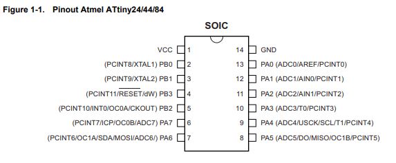
ATtiny44 data sheet
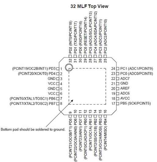
For my first attempt in this assignment I use an ATtiny 44 microcontroller to redraw the "hello.fdti.44 board" but after I change it for a Atmega328p and when I review the datasheet I found this differences between them:
- Pin configurations: the ATtiny 44 has 14 PINS and the Atmega328p has 32.
- Tinys can be very tiny up to "medium" sized. Megas can be "medium" sized up to "large" sized.
- Features memory and package size / io capability.
- Etc...
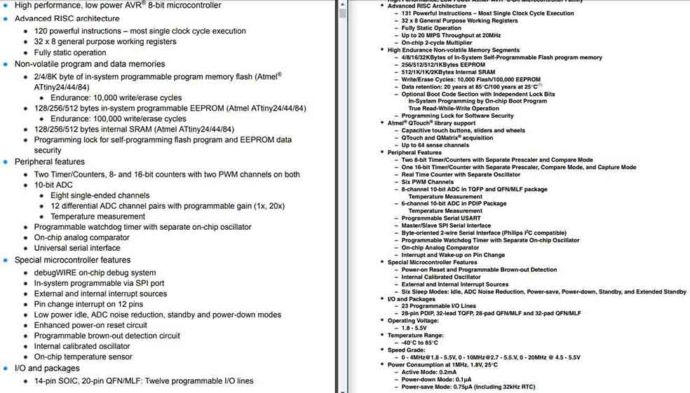
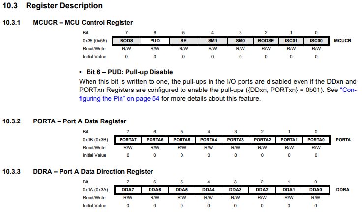
I/O PORTS
Can be an input or an output and internally you turn on a pull up resistor. There are three registers:
- DD is the direction do you talk out or you listening.
- PIN Is where you read what's happening in the PIN it's an input.
- PORT is where you write out to send data out.
ANALOG COMPARATOR (input also)
Compares two voltages ask if one is above or below another. Only gives true or false answer. It can do it very quickly.
ANALOG TO DIGITAL CONVERTER
- Reads in a voltage and gives you a number.
- Multiplexer pick which pin you reading.
- Instead of reading a single voltage you can select two voltages and measure the difference.
- The voltage is a number but you have to relate the number to the range and so the range can be an external reference, the power supply or an internal reference.
- There is a clock read it out if clocked quickly the answer is less accurate but if you coked slowly the answer is more accurate.
Registers
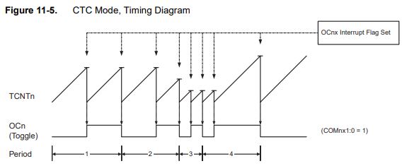
8-bit Timer/counter0 with PWM
You put a number in the register and the counter counts up or down and when the counter is above or below of the number you turn PINS on and off so rather than you have to flip a PIN the PIN flips automatically by this timer counter unit and the you just slowly change number to vary the fraction the on off time.
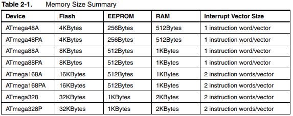
ATmega88 - Atmega328p data sheet
I add the Atmega88 micro controller in the schematic but I'm using the Atmega328p and when I check the datasheet I realized that both of them have the same PIN distributions. They only differ in memory sizes, boot loader support, and interrupt vector sizes. You can check the important information I found in the Week 09.
KICAD
KiCad is an open source software suite for Electronic Design Automation (EDA). The programs handle Schematic Capture, and PCB Layout with Gerber output.
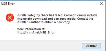
- First I downloaded KiCad 5.0.2 version for windows. And a NSIS error don't allow me to install the software, I try debugging watching some tutorials about how other people solve this problem, then I did it on my PC but windows still doesn't allow me to install. Finally I try with a previous version which was installed successfully.
- Then I downloaded the Fab-components library specifically for Kicad from this link and then load it within the program.
- I started redrawing the echo hello-world board from scratch as Neil recommendation and adding the components first and then organizing them using the this link tutorial as a guide.
- After that I had to assign Names and Values to the components and some lines.
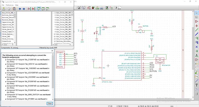
- Finally I run the electrical rule checker and give me some errors, Once I fix them another error appear because of that when I change to the footprint editor the components doesn't appear.
- We were wasting to much time trying to fix this errors and we decided to change to Eagle software.
Slideshow 12: Click on the arrow to see the images!

You can download the file:
EAGLE
Autodesk EAGLE is an electronic design automation (EDA) software. Enabling printed circuit board (PCB) designers to seamlessly connect schematic diagrams, component placement, PCB routing, and comprehensive library content.
I found this eagle tutorial that make my job a lot easier and this is the work flow I followed:
- We use the 6.3.0 version, the installation was simple and successful.
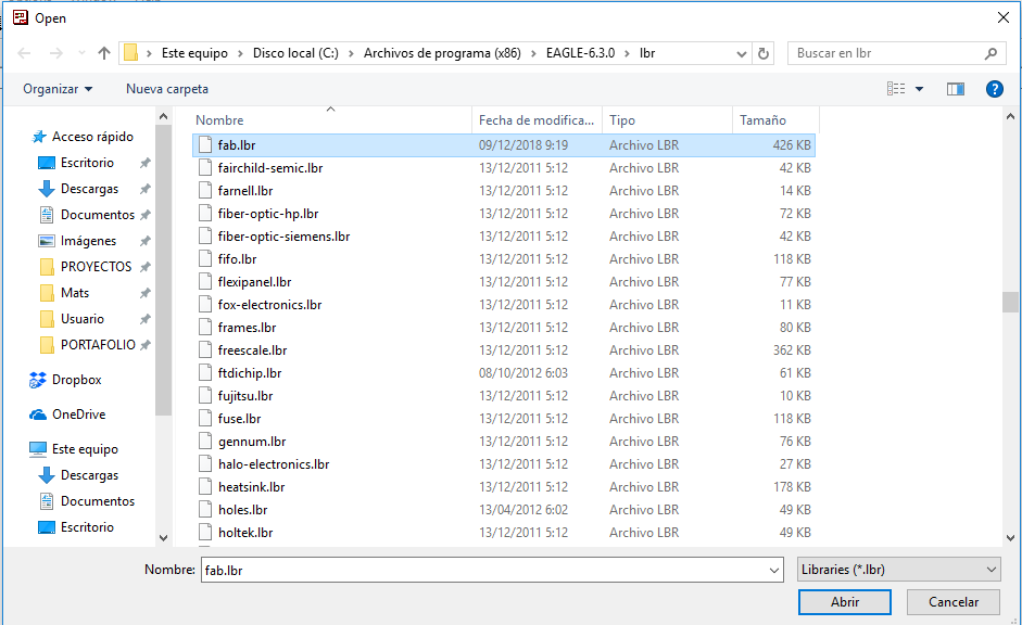
- I Downloaded the fab.lbr library specifically for Eagle and then load it to the software library.
- In my case I use Windows and the file path for the libraries is C:\Program Files (x86)\EAGLE-6.3.0\lbr
- Go to the top toolbar and select the "library"¨menu.
- Select "use" and open the .lbr file you downloaded.
- Now go to "add a component" all the libraries are available.
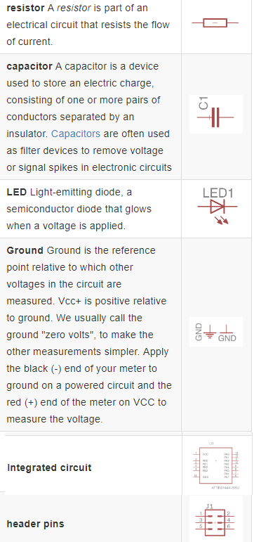
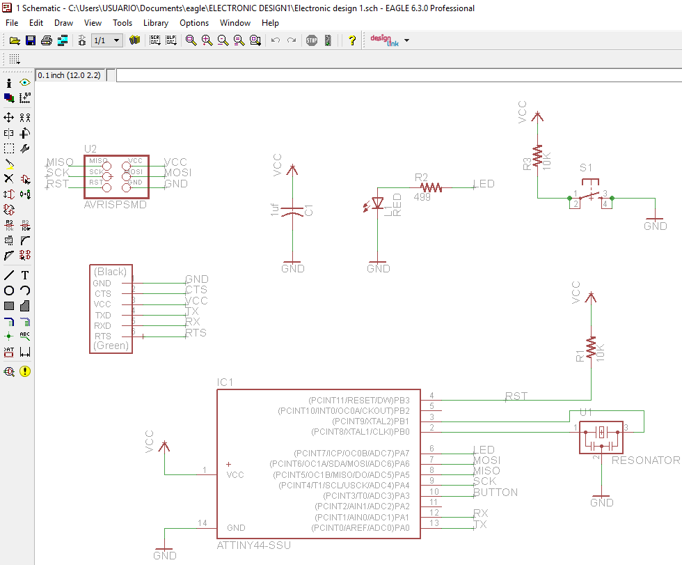
- I started drawing from zero the hello.fdti.44 schematic again, first I add the next the components (For a better understanding of some concepts I review this link):
- 1 X ATTINY44-SSU / ATMEGA88-THIN (micro-controller)
- 1 X red LED (the side with the line is the cathode and connects to the ground side, we need to use a 499 ohm resistor to avoid blowing out the LED)
- 1 X 1 uf capacitor
- 2 X 10K resistor
- 1 X 499 Ohm resistor
- 1 X 1X6 FTDI-SMD-header (communication)
- 1 X switch 6mm (Button)
- 1 X AVRISPSMD 2X03SMD (Programing port)
- 1 X PINHD-2X2-SMD
- 1 X RESONATOR (external clock:increase the clock speed of the processor and more accurate).
- After that I organize them and create connections between them and also copy some components like resistor, GND and VCC to create new connections. This are the commands more useful to me:
- add = open the libraries and you can add components in to Schematic view
- move = move an item
- copy = copies an existing component.
- net = makes a logical connection
- value = add value to components (i.e. ohm rating)
- name = names a component
- group = groups components in Layout view together; if you right-click, then you can choose Move: Group to move the grouping
- ERC = electronic rules check; this ensures your board will actually work (use in schematic view)
- DRC = design rules check (in board view) - keep all the default settings (16 mil is fine); it should display a "no error" message in the bottom left hand corner of the screen
- info = then click on text to get properties of the text
- Label = create a label which allows you to assign a name and create a connections.
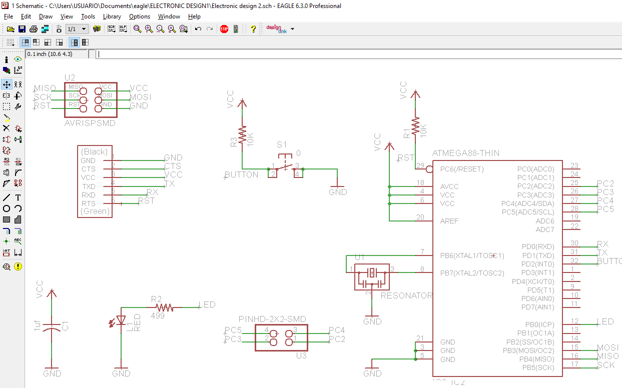
- Once finished the schematic our instructor decided to replace the micro controller ATTINY 44 to ATMEGA88 to challenge us. I had to erase the ATTINY 44 and instead of that I add the Atmega88 and create the connections between the pins of the micro-controller and the components.
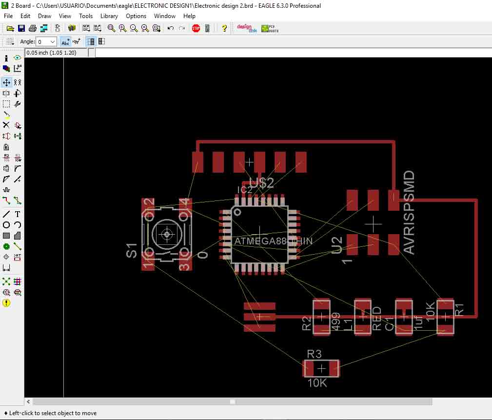
- After having finished the schematic again. I switch to the board view (Go to the top menu > File > switch to board) and organize my components so that the connections are as close as possible to each other. This are the commands most useful to me:
- Move: to move each individual component around.
- Route: to route each trace. The wire will turn red as you route it into place.
- Ripup: to undo the route made before.
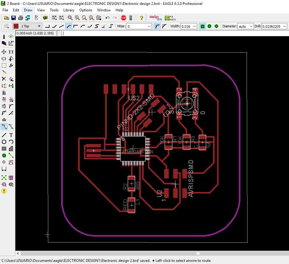
- The next step was to create the connections between the components through traces. This stage was difficult for me because some traces lock the way of the others components connections. But at the end I managed to solve it with the advise of my instructors.
- Then I had to check if there were any errors and I had a few, like connections were broken, I just had to put junctions in the right place to solve it.
- I add a frame using another layer, after that I export the two files (traces and cut) to image 1000 dpi.
- To automatically create a bill material list I use BOM.
- Open your schematic (.sch) file from the Autodesk EAGLE Control Panel.
- Next, select the ULP run-icon tool at the top of your interface and choose the bom.ulp file in the list of available ULPs.
- The bom.ulp file should show up at the top of your list.
- Open your schematic (.sch) file from the Autodesk EAGLE Control Panel.
- You should now be looking at the EAGLE: Bill of Material dialog. From here you can see all of the parts you placed on your schematic and their associated data. You'll now want to choose your Output format and then select the Save. button.
Installation:
Schematic (.sch) - logical components:
Micro-components:
Board Layout (.brd):

You can download the file:
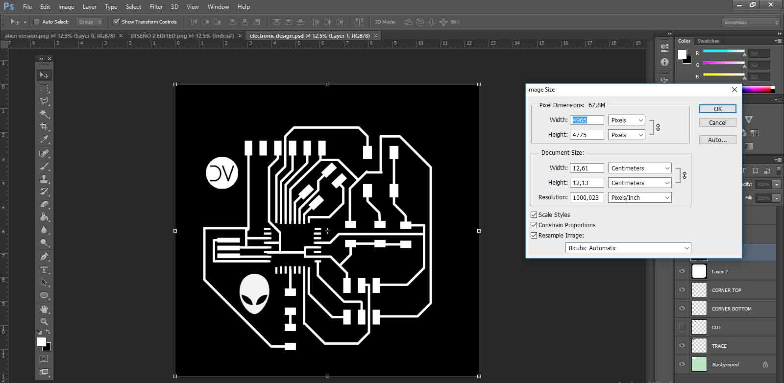
Photoshop
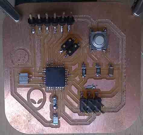
I use this software to edit my PNG file and add an alien and my initials.
- I opened the png file and the file doesn't allow me to modify, so I had to create a new one with the same parameters of the image size, and then copy the traces and cut to this new file as different layers.
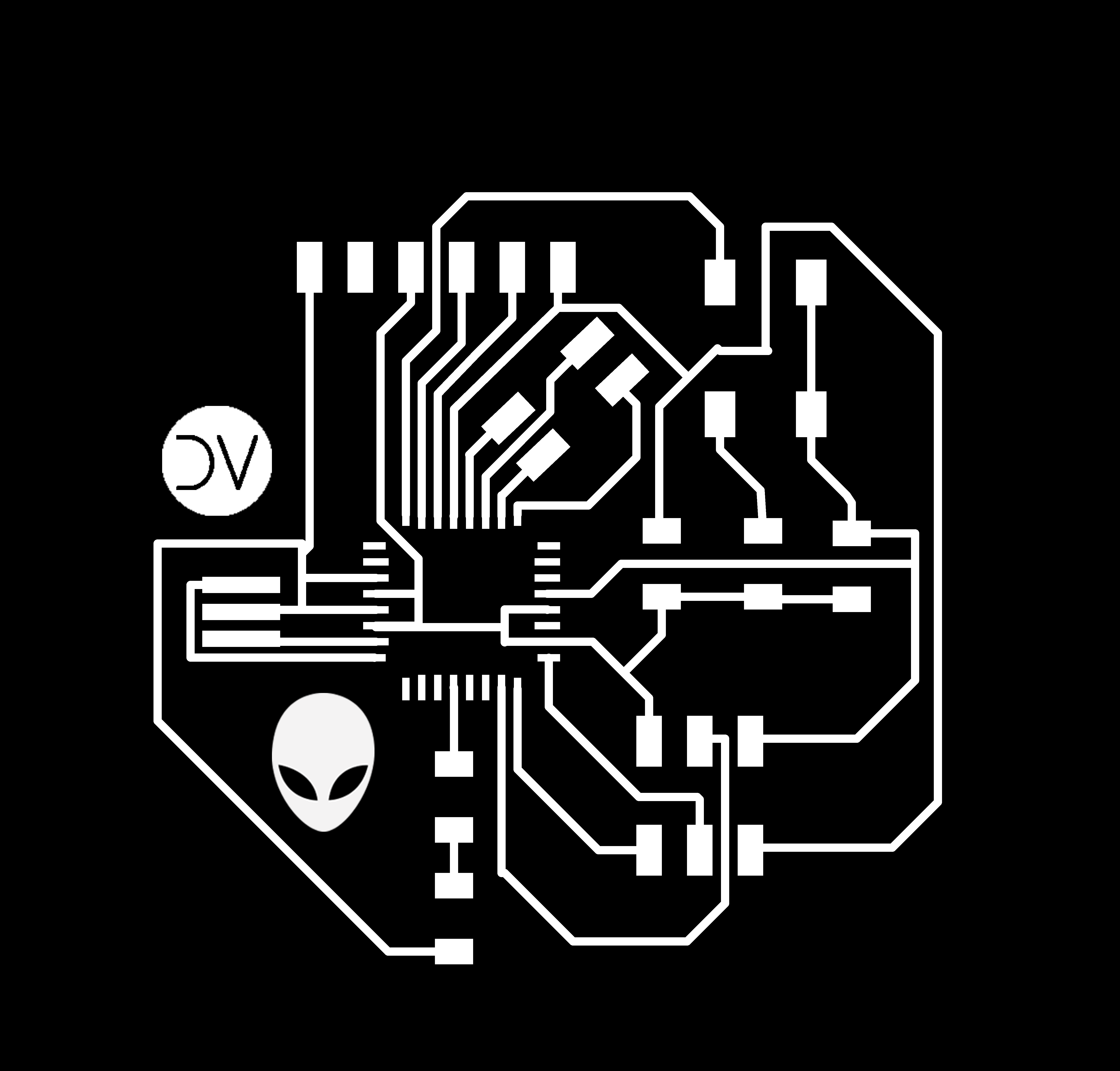
- Then I add the alien face and my initial as a new layers.
- The next step was to save the traces and the cut files as png.
- I realized that the original images size changed to double so I had to fix this error creating again the png files.
You can download the files:
Mods
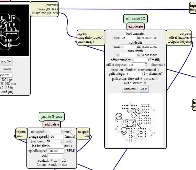
After that I upload the images to MODS G-code mill 2D png program.
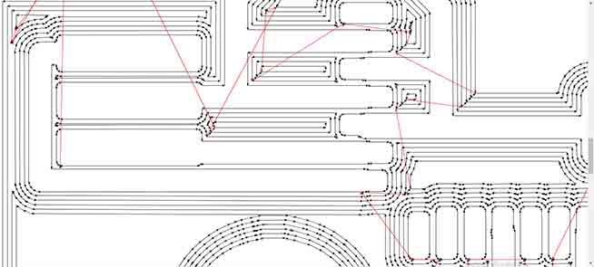
First attempt: In the traces file I use the same settings that I used for my second programmer. The settings for "tool diameter mm: 0.35" give me two errors which were two tracks joined.
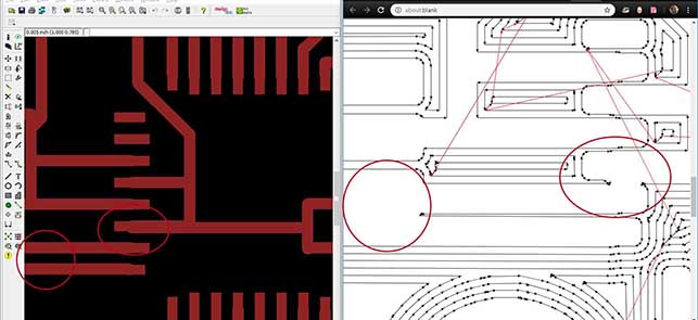
Debugging: I had to change the settings for "tool diameter mm: 0.25", finally the file was correct.
You can download the files:
.nc)
AutoLeveller
To prepare "autoleveled" G-code is quite easy, just open the AutoLeveller, point it to the G-code generated in MODS, and hit "go". Out the other end comes your G-Code with the autoleveler magic included.
LinuxCNC
Open the G-code with the autoleveller file included and make sure to follow the correct process and use the right milling cutter.
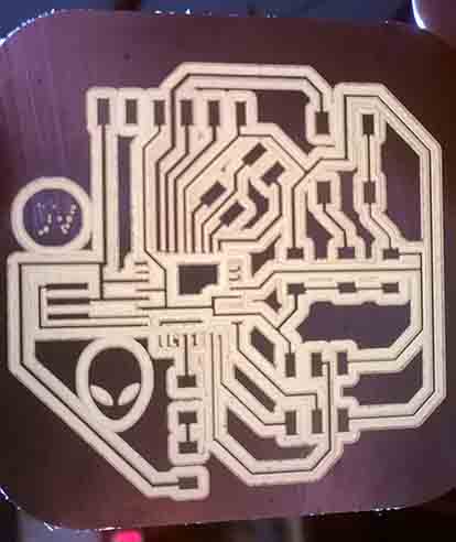
Solder
This part was easy after soldering the Alex version two times. And the offset I use help a lot.
Arduino
Arduino is an open-source electronics platform based on easy-to-use hardware and software. It's intended for anyone making interactive projects.
Hacking Arduino software to program a non Arduino circuit board.
We had to make some kind of hack to program our electronic circuit using arduino software. You can see the all process in the next video:
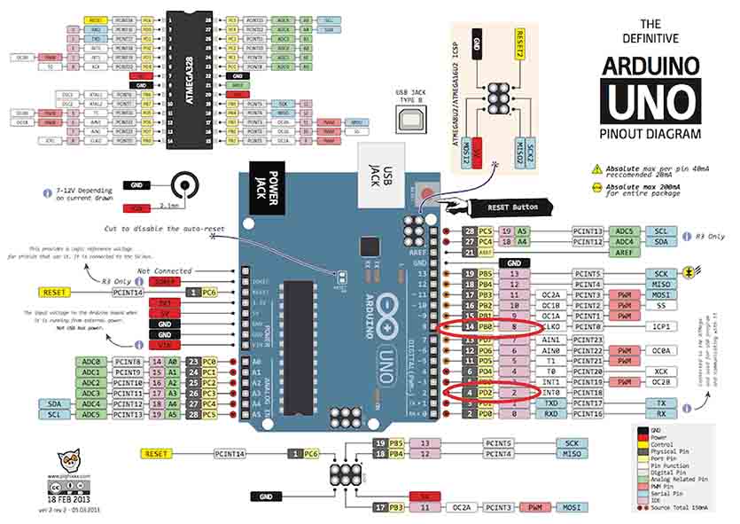
Arduino Pin out:
I had to check where the pin outs of my microprocessor are located respectively to the arduino pin outs, then I put the corresponding number of the pin outs in the arduino code and finally upload the corresponding code to my Alien circuit board.
Blink:
I had to enter the number 8 as an OUTPUT corespondent to my LED pin out (PB0 in my micro-controller) and then change the delay from 1000 to 100 milliseconds to make the light blink faster.
You can download the files:
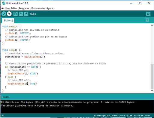
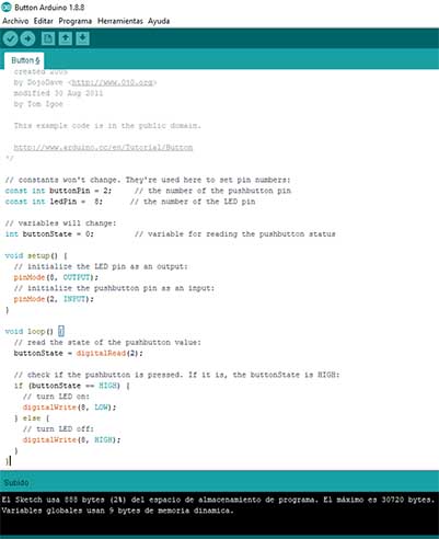
Button:
I had to enter the number 8 as an OUTPUT corespondent to my LED pin out (PB0) and then put the number 2 as an INPUT correspondent to my button pin-out (PD2) the delay from 1000 to 100 milliseconds to make the light blink faster.
You can download the files:
Watch the video:
Testing the equipment (Group assignment)
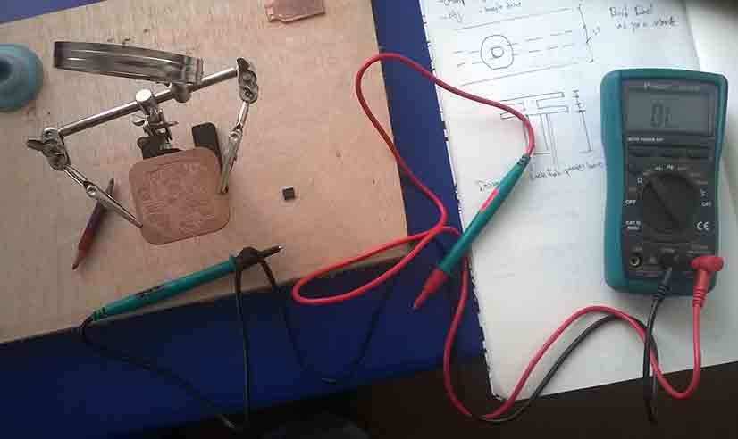
Multimeter:
Is an electronic measuring instrument that combines several measurement functions in one unit. A typical multimeter can measure voltage, current, and resistance.
We use this device to know which tracks and components are connected with each other through the circuits. This was really useful when I was looking for the error in my first attempt of my programmer.
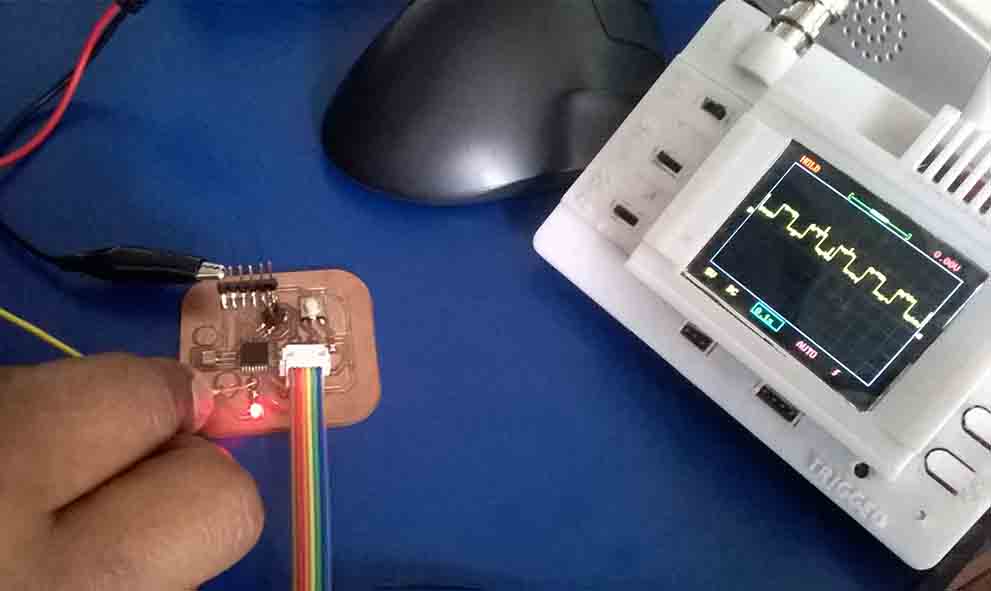
Oscilloscope:
An oscilloscope is a laboratory instrument commonly used to display and analyze the waveform of electronic signals. In effect, the device draws a graph of the instantaneous signal voltage as a function of time.
We use it to see and analyze the wave form of my led when I program it to blink very fast, also to see and analyze the wave form that produce my button.
Conclusion:
We had troubles using KiCad so we change the software to a previous version of Eagle and this one works well.
Some important recommendations in circuit boar design are:
- Review the data sheet of your micro-controller.
- It's better when you design the breaks of your tracks in angles.
- Review and compare the pin-out of arduino vs your micro-controller.
- Be very careful in all the process of mods, png, solder, programming and debugging.