Week 09
Embedded Programming
Assignment:
- Group assignment
Compare the performance and development workflows for other architectures.
- Individual assignments
Read a microcontroller data sheet.Program your board to do something, with as many different programming languages and programming environments as possible.
- Learning outcomes:
Identify relevant information in a microcontroller data sheet. Implement programming protocols. - Have you:
Documented what you learned from reading a microcontroller datasheet. What questions do you have? What would you like to learn more about?. Programmed your board. Described the programming process/es you used. Included your code.
ATmega328p Data sheet
The first thing I did is understand what are the different terms used in the data sheet:
Memory: Exist different kinds of memory.
- Registers: is a kind of memory allow to operate the microcontroller adding two numbers.
- Static ram: is where you store data an you can access quickly
- Dynamic ram: is slower but allow to store more memory.
- EEPROM: keeps it value after the power is off, the circuit can write his own memory the processor can save a value and then remember when the power is on.
- Flash: can write his own flash can do it easily but is denser and is why you store programs, if you want to put programs or a lot data goes in to the flash.
- Fuse: use the fuse calculator and pick your part and all the seethings configure.
Peripherals: is everything else that is not the register instructions.
- Ports: each pin is a little machine (IO ports).
- A/D: analog to digital, can measure voltage and turn into a number.
- Comparator: allows to compare two voltages, tells is greater or lesser. Turns a number into analog voltage to generate wave forms out.
- Timer: measure time.
- Counters: measure counts.
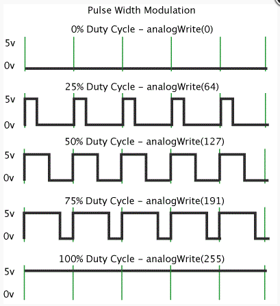
- PWM: Pulse width modulation, if you want a light bright or a motor run faster or slower or a speaker louder, turning a pin on and of very quickly rater than varying a voltage.
- USART: to communicate a serially.
- USB: hardware protocol.
Registers: talk to the memory, the number of the bits is the word size. A processor with a bigger registers can do more work in one operation.
Data sheet
Pin configuration: Show the distribution of the pins and the orientation.
Pin Description:
- VCC: Digital supply voltage.
- GND: ground
- Port B: is an 8-bit bi-directional I/O
- Port C: is a 7-bit bi-directional I/O port
- PC6/RESET: If the RSTDISBL Fuse is programmed, PC6 is used as an I/O pin.
- PortD: is an 8-bit bi-directional I/O
- AV: is the supply voltage pin for the A/D Converter
- AREF: AREF is the analog reference pin for the A/D Converter.
- ADC: serve as analog inputs to the A/D converter. These pins are powered from the analog supply and serve as 10-bit ADC channels.
- Analog to digital converter: When you going to use sensor. Registers is where you configure it.
- Instruction set summary: specify the number of clocks
- Electrical characteristics: Shows the minimum and maximum voltages and temperatures that the microcontroller use and support.
Clocks
- Time sources: The device is shipped with internal RC oscillator at 8.0MHz
- RC clock: resistor and a capacitor, calculate time charging and discharging. Is good calibrated at 10% and calibrated at 1%.
- instructions (datasheet)
I/O ports: can be Inputs or outputs, internally we can turn on or pull up resistors. Has the next registers:
- DDRB: is the direction, do you take out or you let in.
- PINB: where you read whats happening if it's an input.
- PORTB: where you write out to send the data out.
- Comparator: compare two voltages, gives true or false answer.
- Analog digital converter: reads in a voltage and gives a number. A multiplexer that picks the pin you are reading. Optionally instead of reading a single voltage you can read two voltages and measure the differences. Optionally there is an amplifier and a sensor to measure the temperature.
Comment:
I would learn more about how work the outputs in relationship with the micro-controller. I would like to know what happed if I turn on the internal clock and I add another external clock. I could affect the output result?
Programming language
A programming language is a formal language, which comprises a set of instructions that produce various kinds of output.
Arduino Software
It's a program with compilers that produce binary machine code for the target processor. The Arduino integrated development environment (IDE) is a cross-platform application (for Windows, macOS, Linux) that is written in the programming language Java.
Sketch
A sketch is a program written with the Arduino IDE and are saved on the development computer as text files with the file extension .ino.
Hacking Arduino Software to program a non Arduino circuit board
I did this in the week 07 check the link located above.
I did this in the week 07 check the link located above.
I did this in the week 07 check the link located above.
C code
We choose to use C Programming language to program our boards.
Programming with this language was more complicated than programming with Arduino, but was a really good exercise to understand the process behind Arduino software.
Blink:
- First I copy Neil's Make Code ( hello.arduino.328P.blink.make ) to a new empty document in Note pad ++.
- The next step was to change some information like the project name, and the fuses information that correspond to the microprocessor of my Alien circuit board.
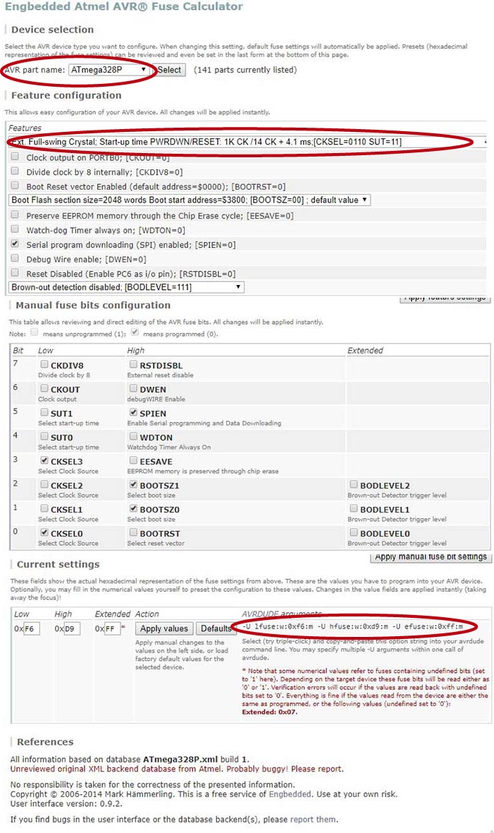
- I use a Fuse calculator to know the right fuses data, for that I had to choose my AVR part name: ATmega328P. In feature configuration I choose: Ext. Full -swing Crystal; Start-up time PWRDWN/RESET: 1K CK/14 CK + A.1 MS: [CKSEL=1110 SUT=11]. The AVRDUDE arguments result was -U lfuse:w:0xf6:m -U hfuse:w:0xd9:m -U efuse:w:0xff:m. (In this part was important to remember don't check Serial program downloading in the features window)
- After that I change the fuses data to -U lfuse:w:0xf6:m and then I save the file as blink.c.make, finally the make file was ready.
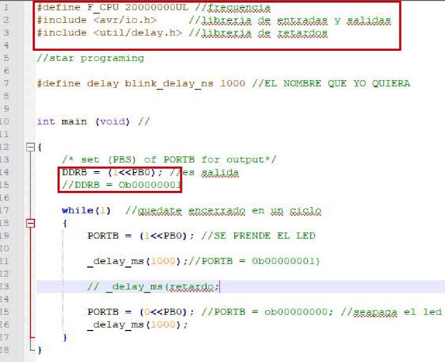
- In a new empty NotePad ++ file I create the blink.c code with the help of Alex who is guiding us in this assignment. One important thing was to define the frequency of the CPU to 20000000 and add the libraries for the delay and for the Outputs and Inputs. One thing that take my attention was about the two different ways to express the code using zero and one numbers.
- In the folder where I had located my blink codes give right click and select git bash here, and type the next codes:
- avrdude -c usbtiny -p m328p
- make -f blink.c.make
- make -f blink.c.make program-usbtiny-fuses, (In this part an error 1 happen because I didn't have my programmer connected to my PC so I just had to connect it).
- make -f blink.c.make program-usbyiny


Slideshow 15: Click on the arrow to see the images!
