15 - Mechanical Design, Machine Design
What I Did For The Group Project
Tools & Assignment
 Mechanical design updated for 2019 evaluation standards!
Group assignment: part 1
Mechanical design updated for 2019 evaluation standards!
Group assignment: part 1
- Design a machine (mechanism + actuation + automation), including the end effector, build the passive parts and operate it manually.
Group assignment: part 2
- Plan and make a machine.
- Document the group project
Individual assignment
- Document your individual contribution
Learning outcomes
- Work and communicate effectively in a team and independently
- Design, plan and build a system
- Analyse and solve technical problems
- Recognise opportunities for improvements in the design
Have you?
- Explained your individual contribution to this project on your own website
On the group page, has your group
- Shown how your team planned and executed the project
- Described problems and how the team solved them
- Listed future development opportunities for this project
- Included your design files
- Optionally included an approx. 1 min video (1920x1080 HTML5 MP4) + slide (1920x1080 PNG)
(Copy of my 2016 website, with spelling corrections :)
In 2016, my team decided to create a random answer machine, otherwise called
The Great Answer Machine
The basic concept was to have an interactive machine which perceived sounds and responded with any one of several arbitrary pre-configured answers (randomly).
The response mechanism was a pointing device controlled by an inverse Delta, stepper motor driven, rail system (more information can be found on official page).
You might be thinking to yourself
and let me tell you, it may seem dumb at first (I was one of the people who voted against it), but the final product was utterly satisfying.
Here is proof
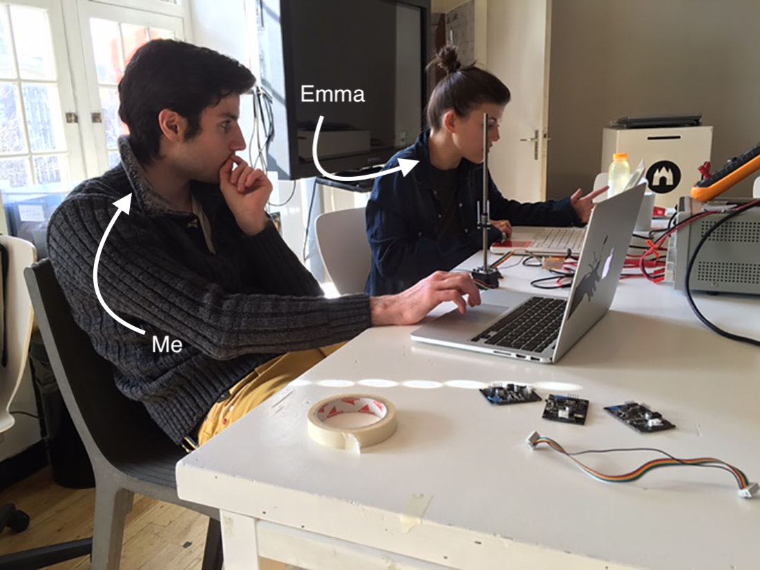
While the rest of the team worked on designing & putting together the machine I worked on the code to operate the machine.
Credits to Marije for designing the header for the main page & for this page
The Process
The first step of the programming phase was setting up the hardware.
Having a total of 4 x Gestalt nodes and 1 x Netfab I was able to get into the programming directly after understanding how to connect up the board correctly.
Fortunately for me Emma sat with me and showed me how to connect up the board.
After the necessary basic introduction I was left on my own to figure out the programming basing myself on the documentation from the previous years:
Connecting the boards
Connecting the Gestalt Nodes to each other are amply documented on the official fab academy site dedicated to them -> m-mtm
The only difference for us was that they had been already flashed, so there was no need for us to do it, and the FabNet had already been milled and stuffed following this documentation.
this was done by the students from the previous year who themselves followed the general fab academy guide.
Programming
Dependencies
Python Install (Required)
-> Download and install the version with the closest release date; for me 3.4.4
Pyserial
There are some libraries which I have installed in the past, which some of the guides above suggest to using, while some others don’t. Because I can’t verify whether having installed them makes a difference, but here they are anyway:
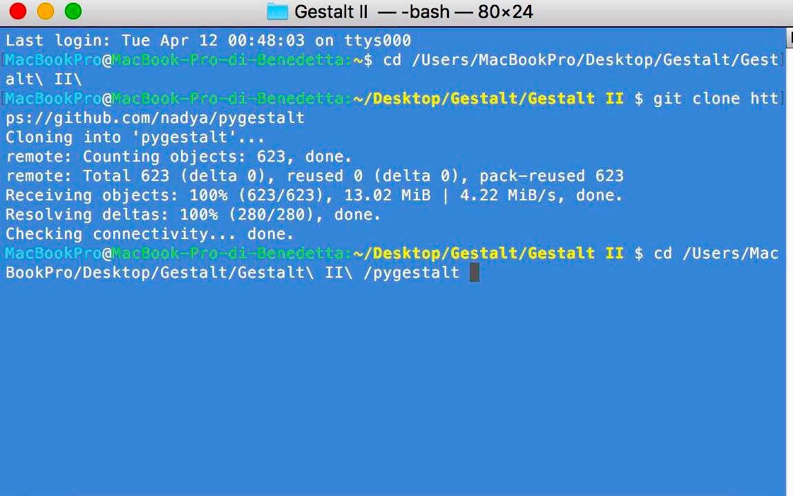
The first step with programming was cloning the pygestalt git repository.
This is done through the terminal by choosing the folder you want to save the repository and cloning the git directory:
cd /[desired directory] (eg. cd /Users/MacBookPro/Desktop)
git clone https://github.com/nadya/pygestalt
Once this is completed we open with the directory where we saved
[All steps shown in the picture below on each line]
The next step is installing the setup.py this is done by running the following command in the terminal:
sudo python setup.py install
If you have a password on your computer it will ask for it, just type it in and hit enter.
[This is what it should look like]
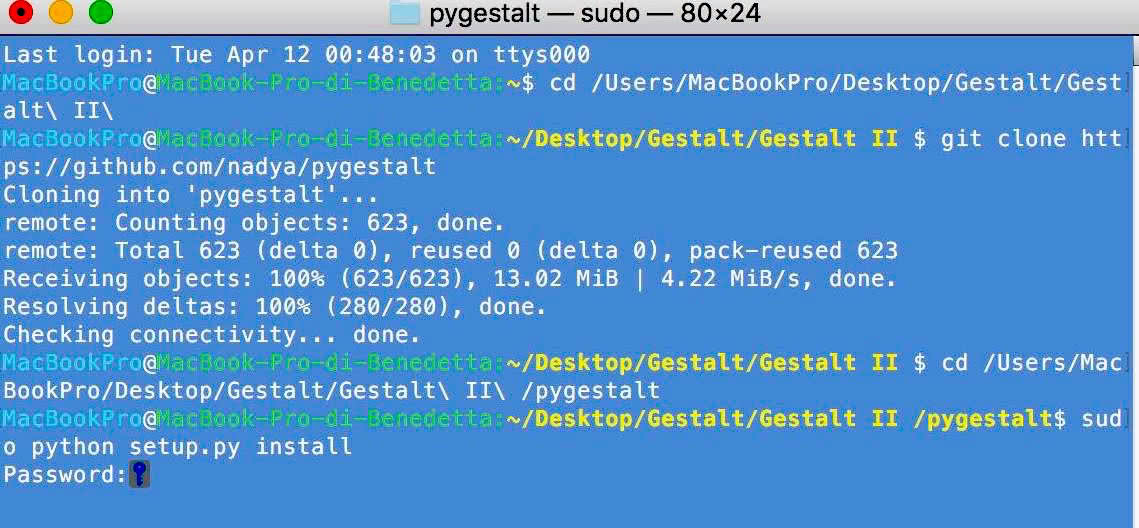
When you’re typing in the password the cursor on the terminal won’t move and no characters appear, this is normal, just type out your password and hit enter, it will work if you typed it right.
Once you hit enter and no errors pop-up the next step (if you are on OS-X) is to check the ID of your FTDI cable.
This is done by inserting the command /dev/tty.usb in the terminal when the FTDI cable is connected.
It should give an output similar to -> /dev/tty.usbserial-FTXW4F9H
(which is the ID of my own FTDI cable) all of this name is essential!
We can then open to edit the xy_plotter.py file, this can be found in the pygestalt/examples/machines/htmaa
(what you use to edit this file is up to you, I used Xcode).
Search for the method initInterfaces and changed the portName definition to /dev/tty.usbserial-[your_FTDI_ID] (eg. /dev/tty.usbserial-FTXW4F9H ).
[It should look like the following]

Snap Shot of Code
As mentioned in Getting started with Gestalt nodes you will also need to install the FTDI drivers to match with your OS.
After this was done, what is left is personalizing the code to our need.
Since we are going to use three axis, and the xy_plotter can only controls two, I needed to add the capability of controlling another one.
The other examples in the folder helped in understanding the underlying logic, also the official documentation was helpful.
Essentially I modified the original program to contain references to a third axis by mimicking the existing axis.
[This consisted of the following changes]
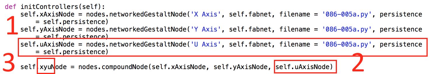
1. Added a self.uAxisNode statement, where I define the third node
2. Added the self.uAxis node to the definition of the xuNode instance of compoundNode which controls the nodes as a set of axis
3. Changed the name of the compoundNode instance from xyNode to xyuNode
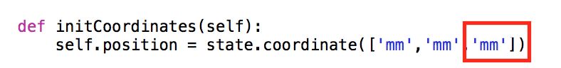
Added a third mm parameter to the possible move function state.coordinate which controls the displacement of the motors: (before it was ['mm','mm'])

Set the kinematics to 3 instead of 2

Added a third None to the definition of setPosition
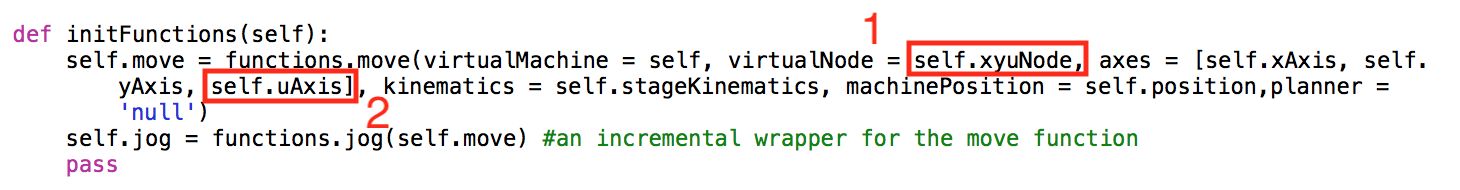
1. Updated the name of the self.xyNode to self.xyuNode to match our previous change
2. Added in the definition the self.uAxis parameter.
U vs Z
I don’t remember exactly why I used U as a third axis name and not Z,
but I believe it was to do with the fact that since the movement isn’t cartesian I didn’t want it to be confused with cartesian axis.
Moves
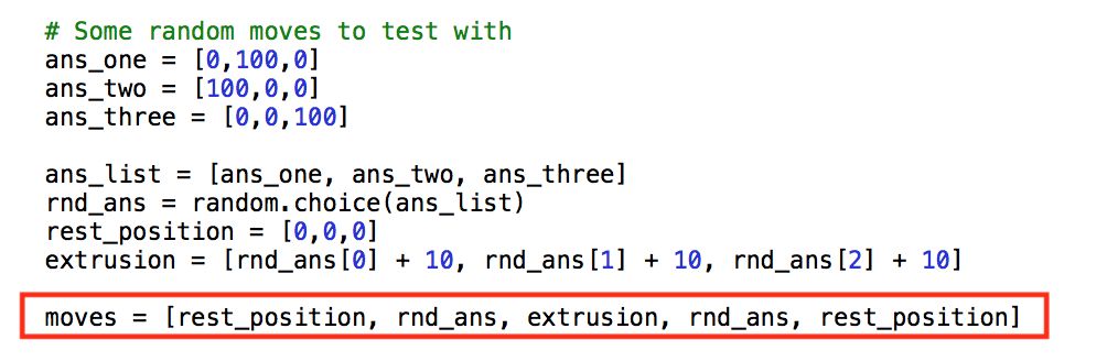
Code which establishes the series of moves to perform
Moves Code Explained
With the above code we can set an indefinite amount of coordinates which define answer positions/
here we only have three answers represented as ans_one, ans_two & ans_three
After adding them to a list, we use random.choice (python docs) to pick an answer.
The moves are a concatenation of standard moves:
1st Rest position
2nd Change to face randomly picked answer
3rd Move hand uniformly up (extrude) towards answer
4th Return to home position
The random answer is embedded and executed in a standard series of moves to ensure that the extrusion and returning to the zero point are standard amongst all answers.
After testing, the motor response seemed quite fast and does not allow the person to see the answer for long enough; the move matrix is customizable and delayable this should be done to te users desires.
I would also like to note that now there are three parameters instead of two, to control all three motors.
The positions of the answers can not be derived mathematicallysee note so they should be mapped manually, thus I wrote the code Manual control to find the position of all answers, shown below.
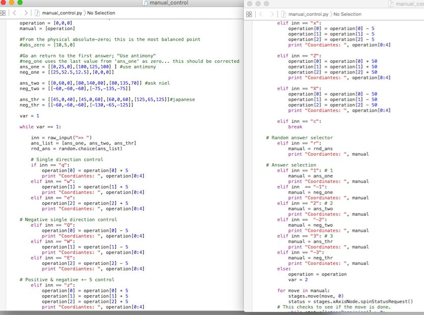
I would also like to note that now there are three parameters instead of two, to control all three motors.
While this is useful to find positions of his is very susceptible to slight changes in the structure and is prone to failure.see note
2019 note to see
Here I state things such as “can not be derived mathematically” as well as “very susceptible to slight changes” but I don’t really explain why.
The reason for these faults is that the answers are fixed in place on the upper arch, and have been arbitrarily placed. Without any way to zero the axis (knowing absolute values rather then relative) it’s impossible to achieve repeatability with slight structure changes.
Looking back I could have implemented some EMF-spike sensing to add some homing capability, but it would have been too difficult for me to do at the time.
Using the above methods every answer can be mapped, saved as a variable and added to the answer list.
End Result
Download The Files
List of Useful Links
Essential
-> Modular Machines that Make (m-MTM): Cardboard CNC
-> Getting Started With Gestalt Nodes
Links to needed software
-> Installing Python and PySerial
-> FTDI drivers
Documentation to implement the Python code
-> Gestalt Docs
Other projects needed for inspiration and debugging
-> Making a Machine - Happylab Vienna - 2015
-> Making a Machine - FabLab Frosinone - 2015