7 - Electronics Design
The Art of Re-Arranging Components
Tools & Assignment
 Updated for 2019 evaluation standards!
Group assignment
- Use the test equipment in your lab to observe the operation of a microcontroller circuit board
Individual assignment
- Redraw the echo hello-world board, add (at least) a button and LED (with current-limiting resistor), check the design rules, make it, test it.
- Extra credit: Simulate its operation. Render it.
Learning outcomes
- Select and use software for circuit board design
- Demonstrate work-flows used in circuit board design
Have you?
- Shown your process using words/images/screenshots
- Explained problems and how you fixed them, including how you worked with design rules for milling (DRC in EagleCad and KiCad)
- Included original design files (Eagle, KiCad, Inkscape, .cad - whatever)
(Copy of my 2016 website, with spelling corrections :)
Preamble
This week we deal with circuits, fortunately for me during my physics high-school studies I was thought in ample detail the function of circuits and the theory, making it possible for me to understand the maths, function of components and theory behind this week. However I had never digitally designed a circuit.
Our Sixth Lecture
During this lecture Neil went through a lot of details about circuits, their application and the function of the components, as well as some of the maths involved. It was hard to follow at time since it was pretty fast paced and quite technical, I managed to understand almost everything but from what I gathered it seems that a lot of the information was surplus for this week focus.
Producing The Circuit
The Lesson On Circuits by Emma
The lecture Emma gave us on circuits this week was fantastic, I was impressed by how clearly she taught the potentially tricky to explain subject of circuits.
She also guided us through the functionalities of Eagle, as well as showing us how to export files.
She also shared with us many important files and links which I will list below:
-> A powerpoint (dead link) on using Eagle for Electronic Design
-> A powerpoint (dead link) on exporting files from eagle to the Roland Modela
-> A tutorial website on using eagle
-> Many YouTube tutorials:
- Tutorial 1: Eagle Schematic
- Tutorial 2: Printed Circuit Board Layout
- How to Use Autorouter With Net Classes
One of the most important files she shared with us was the library file for Eagle (files in download section)
Creating The Circuit On Eagle
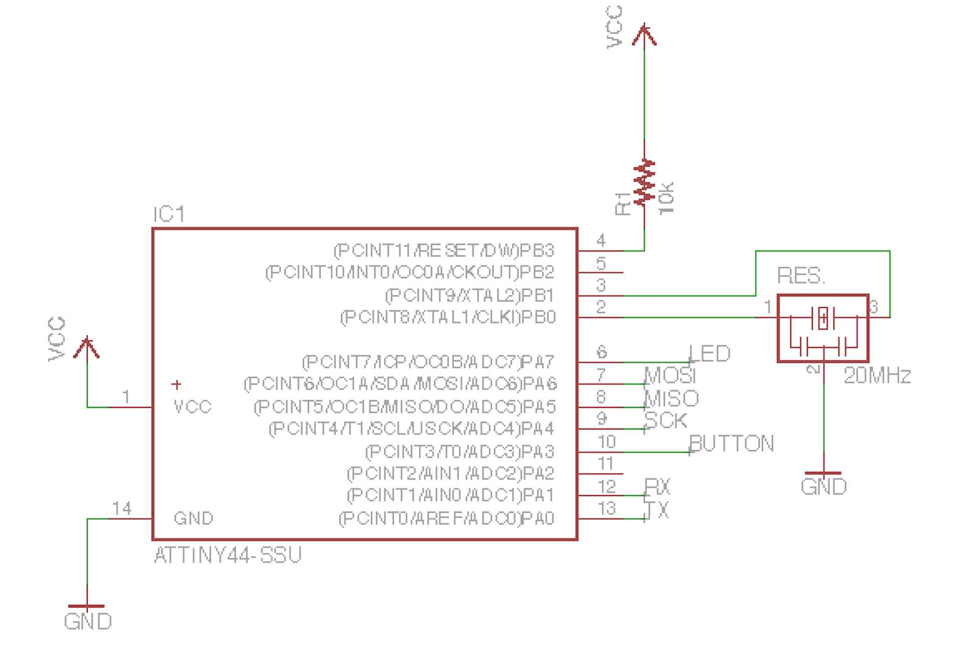
Fortunately the official guide to making the Echo Hello-World board was really clear and guided us, almost too smoothly, through the all process.
I also downloaded the official Eagle library provided on the schedule by Neil, combined with the one from Emma I could access all the components I need to construct my board.
From there it was just a matter of following the instructions and tutorials to complete the assignment. At first I came across some issues, by checking with DRC some errors came up, the lines weren’t more then 0.4mm apart
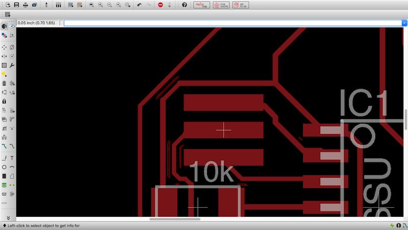
The small red stripes that can be seen between the solid red lines, which are suppose to be the traces are a signal from DRC that the distance between the two lines is less then 0.4mm
which is the minimum distance between lines imposed by the width (1/64) of the end-mill. I solved the issue by reducing the width of some lines.
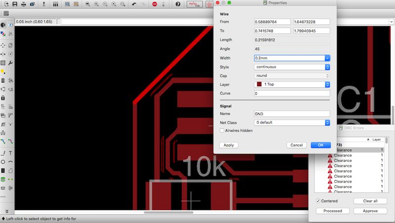
After typing info in the command line and clicking the line the properties can be changed, the one I changed is width from 0.4mm to 0.2mmright.
From the completed design I decided that it looked far too similar to the one from the guide, so I deleted my design file and started from scratch, it connected the components using Autorouter, which was not easy, since achieving 100% connection (which means that all the connections have been made) is very tricky and depends heavily on how well you placed the components in the first place, which takes a LOT of trial and error.
[It also takes a long time if you put effort to ‘high’ (which refers to how hard it tries to make a good route), because it tries out every possible route, similarly to the travelling salesman problem shout-out to all computer scientists, it takes quite a while to solve].
Once that was done I was left with a good looking design file, I added ‘Jack’s Echo’ and the extra rectangular layer for the fab-modules to recognize the edges, and then exported the traces and cut-out as septate png images:
- Monochrome
- resolution:
1000 - area:
full(as explained in the aforementioned,downloadable presentation).
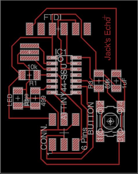
The design of my traces as created by Autorouter
Milling & Soldering The Board
Following the rules from week 4# I uploaded my png to the Roland Modela and produced my Echo board, everything went smoothly this time using the Modela.
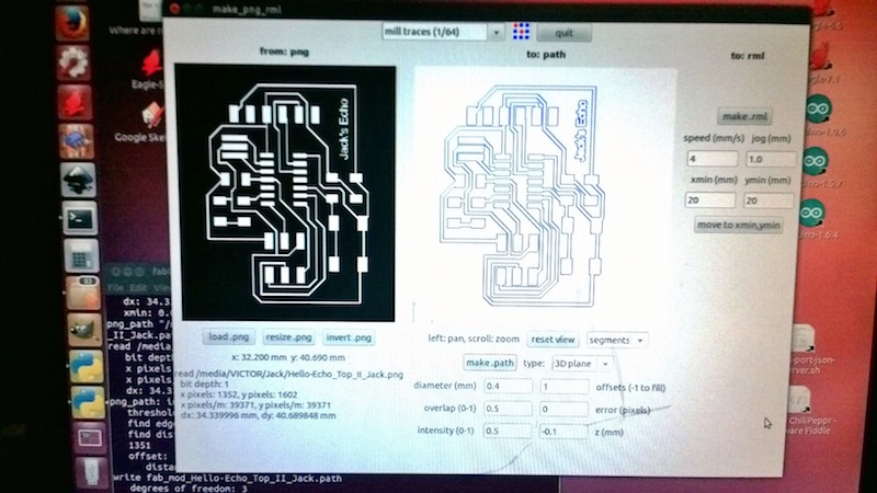
An image of the fab-module settings I used to trace my board. (right click and ‘open on another page to see the larger version of this photo).
This time I decided to try out a new soldering technique for the sake of experimentation: I placed the solder every copper pad before the components themselves, then I placed the components onto of the cold solder and used the heat-gun to melt the solder once again and used a pair of tweezers to place to component in place…
This worked surprisingly well, actually perfectly, I had no shorts at all, I obtained a very clean board and the board was recognized by the computer once I connected it to the ISP, I only had some problems controlling the position of the resonator.
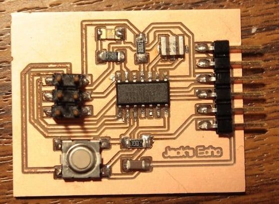
A photo of my completed & soldered Hello-Echo board.
Once I completed it, I checked for shorts across the board with a multimeter, then connected it to an ISP and using the command avrdude -c usbtiny -p t44 on my Mac OS X terminal and after learning that 6-pin headers do indeed have an orientation, the message AVR device initialized flagged that I had been success.
(first message was caused by wrong orientation of pin, second was a successful initialization)
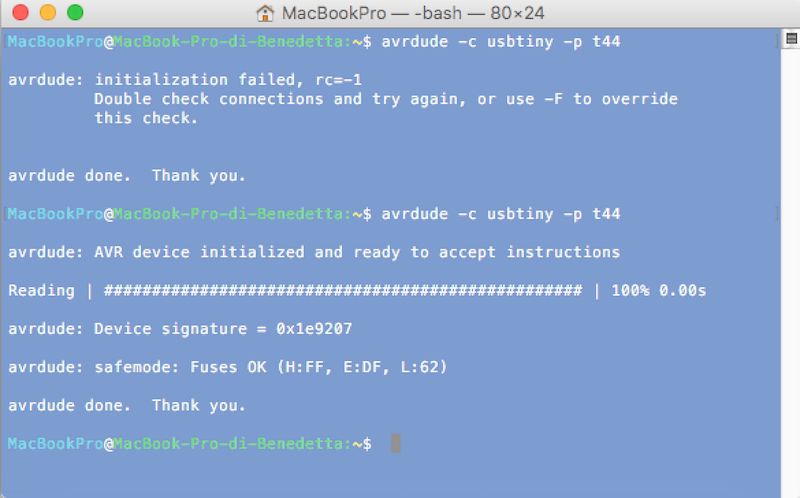
Testing if my board works through the terminal using the avrdude command.
Group Assignment & 2016
The group assignment for this week did not exist in 2016, but we often used tools to check their functioning.
In particular, our most trusted tool was the multimeter, which we used to check for shorts and to verify connections had been properly made.
Testing For Continuity
This is called “testing for continuity”, continuous means electricity can flow freely between two points. This is performed when the board is not powered (often even before stuffing)
-
black probe ->
COMport -
red probe ->
VΩmAport. -
dial -> continuity mode (speaker icon)
You can test if there is continuity between to points by using the two probes. If two points are continuous, contact with the probes will make the multimeter beep.
In case you didn’t expect to be a connection but the multimeter beeps, then it’s a short! In contrast, if you expect a connection between to points but no sound is made then the connection (maybe soldering) isn’t working (with diodes be careful you check in the right orientation).
Testing For Resistance
If however there is a resistor between two points and you want to check the resistor is soldered on well, you can turn to the testing for resistance mode which is nΩ where n is the right resistor range (eg. 2k~20k).
Testing For Voltage
You can also check (in a limited way) to see if signals are sent (ie. pins go from low to high) if the delay between pulses is long enough to be perceptible.
To do this, set the multimeter to DC voltage mode (V, – or ⎓), as well as the right range which for ATTiny boards is 5v and below (thus 20V since that’s the lowest containing that range).
With this setting we will be able to tell if a certain pin goes HIGH or LOW at given time intervals, allowing us to limited amounts of debugging.
(for faster rates an oscilloscope would be needed)
2019
After 2016 I never designed boards again, sadly, even though I found it very fun. This is attributed the the usual issues: lack of machines to use in my vicinity and being busy as student.
Now that I own my own CNC, I would like to spend more time perusing proficiency in this field. Since I feel like I’ve got still a lot to learn.
Because my consciousness of open source / free to use has developed since then I decided to work using KiCad this year (2019) which proved to be much easier and powerful then I expected. As Eagle found itself part of the monopoly that is Autodesk, even maintaining it’s free to use aspects, I will be using KiCad from now on.
Download The Files
-> Fab ISP library file for Eagle
-> Schematic of Board [Eagle]
-> .zip of Folder Containing The Various .jpg Files of The Board