8 - Computer-Controlled Machining
Why Are Big Machines So Scary?
Tools & Assignment
 Updated for 2019 evaluation standards!
Group assignment
- Test runout, alignment, speeds, feeds, and toolpaths for your machine
Individual project
- Make (design+mill+assemble) something big.
Learning outcomes
- Demonstrate 2D design development for CNC production
- Describe workflows for CNC production
Have you?
- Explained how you made your files for machining (2D or 3D)
- Shown how you made something BIG (setting up the machine, using fixings, testing joints, adjusting feeds and speeds, depth of cut etc)
- Described problems and how you fixed them
- Included your design files and ‘hero shot’ photos of final object
(Copy of my 2016 website, with spelling corrections :)
Preamble
Before starting the Fab Academy I had little to no knowledge about CNC routers.
As a matter of fact I had just discovered about their existence a few months prior the start of the Fab Academy, so it goes without saying I had never laid a finger on one.
Our Seventh Lecture
This lecture was mostly focused on how CNC routers work, with special in-depth detail on milling-bit and all its possible variants forms.
Neil’s addressed the topic of safety recursively during this lecture, telling us to be careful about the various safety procedures.
The Computer-Controlled Machining
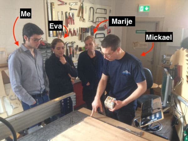
As a prelude to thank all the other members of the Fab Academy @ DeWaag for their patience and for giving up some of their time to compensate for my inability to use the machine.
I was pretty terrified by this machine at first, so much so I gave up on using the machine on Friday on my assigned slot.
ShopBot Setup: a Lesson By Mickael
The ShopBot is a professional machine.
This, as is often the case with professional mechanical equipment, means that it can and will hurt you (either economically or physically) if miss-used.
In other words:

The lesson by Mickael was an intense 3 hours of systematic instructions, he pointed out the most important guide lines, such as:
- Bolting down your work material
- Going from drawing file to milling
- Safety precautions
- Set-up procedures
Things to keep in mind:
-> Eye (& ear) protection is important, make sure to wear it (drill bits do fly)
-> Long hair must be kept tidied up
-> Never leave the machine running un-attended
A Lesson By Mickael
Additionally, these two videos are great for revising the basics:
-> Using The ShopBot - Back to the Basics
-> Getting started with PartWorks
Checklist
The ventilation is controlled by a switch at the back of the room, this enables the vacuum but doesn’t turn it on.
Ventilation Switch

This turns-on the vacuum, and allows for fine adjustment for more or less strength.
I’m still trying to think of a reason why you’d need to adjust the speed of the vacuum, the only thing that comes to mind is loudness, but i’m not sure how that will help when you have a Pneumatic Drill Head™ running in the background.
Can’t you keep it always at max?
Ventilation Speed Control
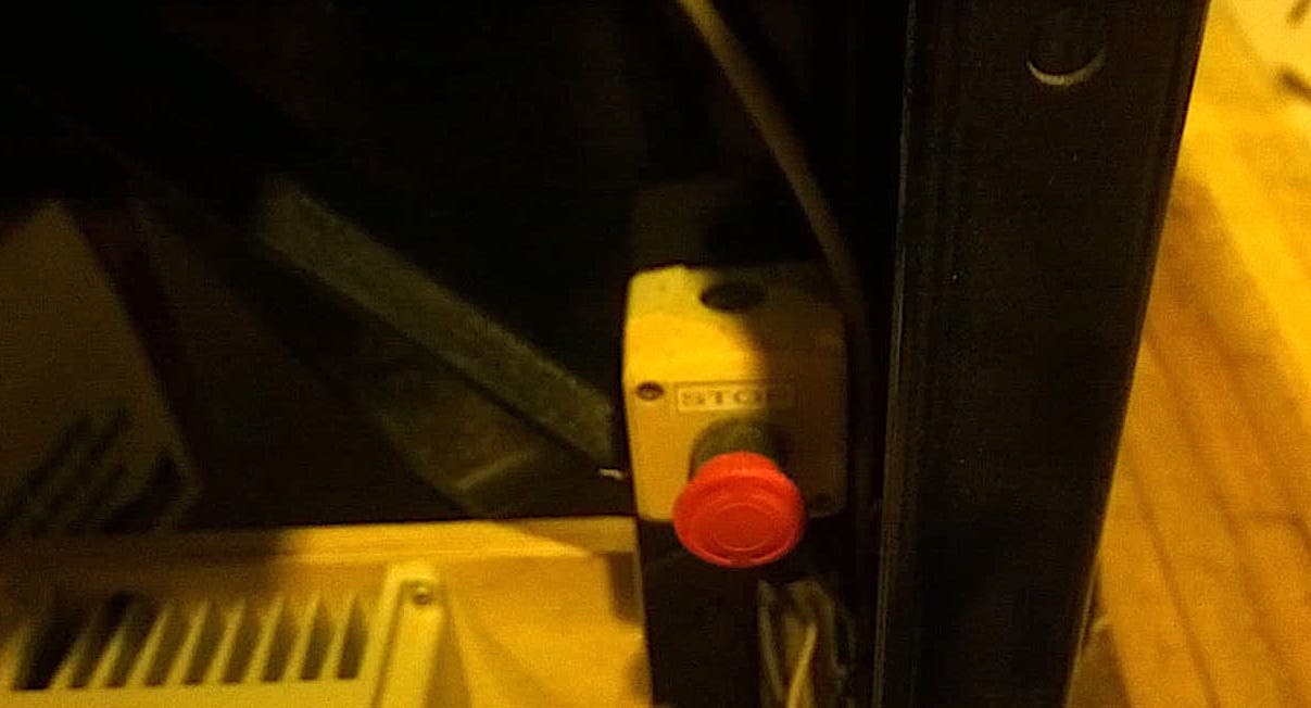
When things go wrong, like your tool head hitting a fixing screw, or your drill-bit breaking, you hit this red button.
Emergency Stop
Before you set your work the sacrificial layer must be clean, this surface acts as the base for your work (and fodder for through-material cuts) and debris may decrease the evenness of your material.
Sacrificial Layer
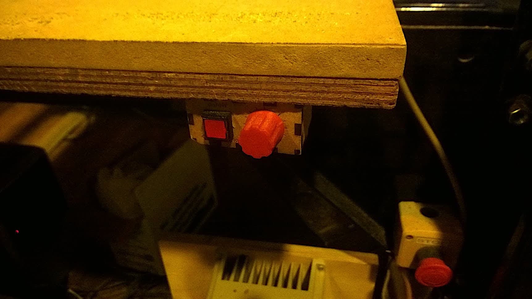
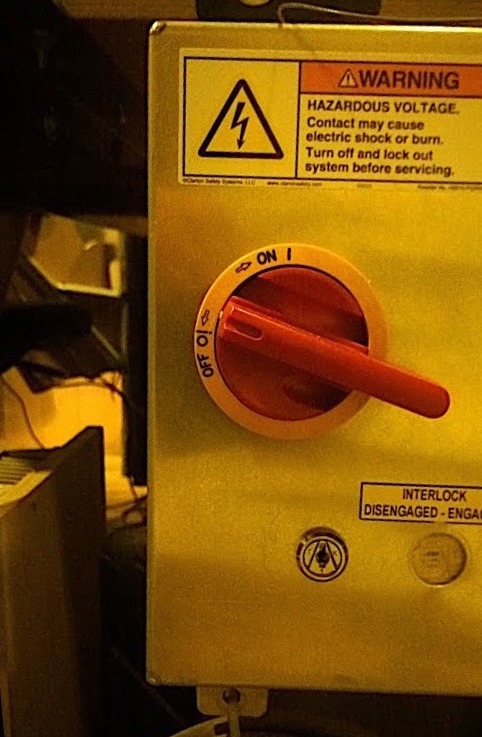
This switch controls the spindle motor, this can only be turned on the when it’s safety key is inserted, and should only be turned on right before starting your job, meaning all other preparations are complete. (The tachometer next to it will tell you the RPM of the spindle)
Milling Router ON/OFF Switch
Creating The .DXF Files In Inkscape
Design Strategy
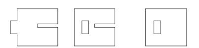
Below I show my inkscape drawing methodology to create the designs for the press-fitting tests and the table.
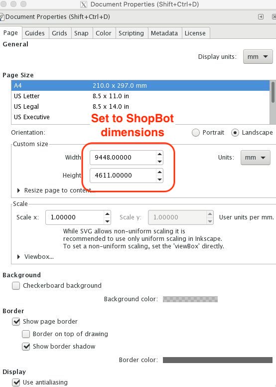
First thing we need to do is set the document properties, this it’s convenient here to set the dimension to match the working area of the ShopBot to Ensure your design isn’t larger than the maximum dimensions.
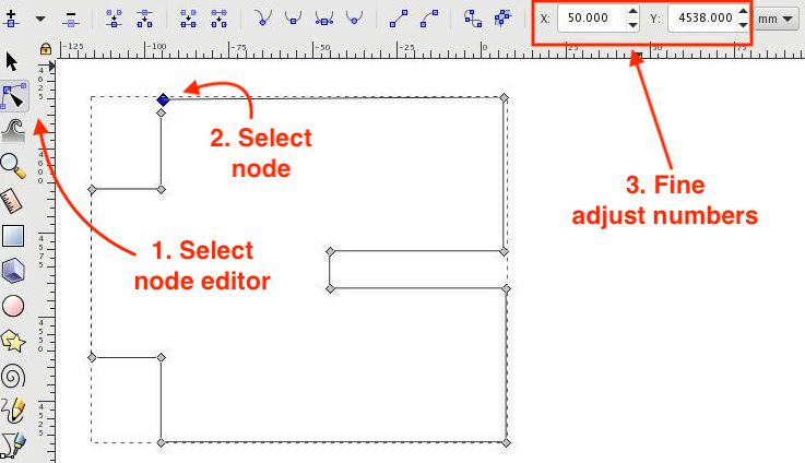
Using Inkscape
We create the rough outline of the part we wish to make using the bezier curve tool, we keep an eye on the dimension to get them close enough to the desired values but without too much worries (we will fix these later),
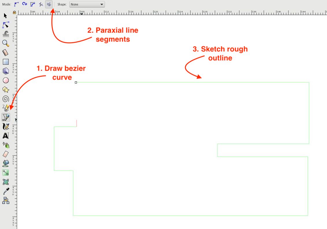
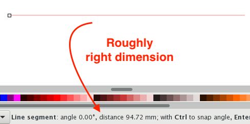
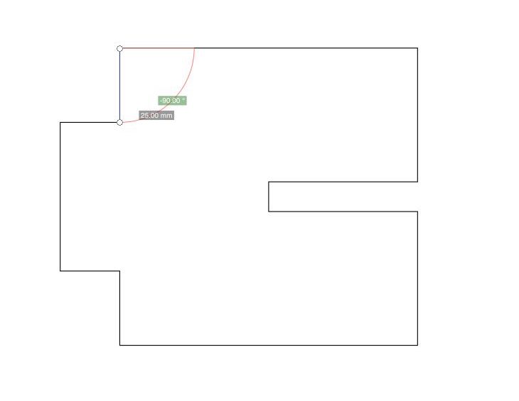
We can the adjust the nodes one-by-one manually to the exact values and dimension we desire.
Perfect End Result
Once the file is created we can export it as a .dxf file by:
-> File -> Save As Copy -> .dxf extension
And we’re done with the design files.
Failed Designs
Amongst the designs I made, there were a few failed attempts:
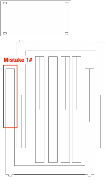
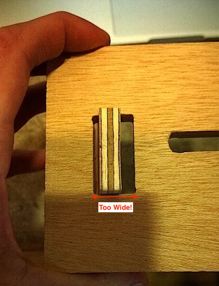
Initially I though that a single line, the width of the tool, would be enough for press fitting, on further analysis I figured that the cut-outs should be at-least the width of the wood, meaning a single pass would be too tight.
Single Pass Cut-outs
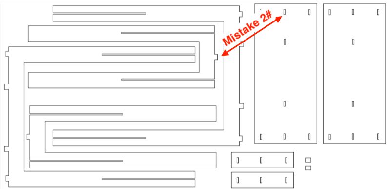
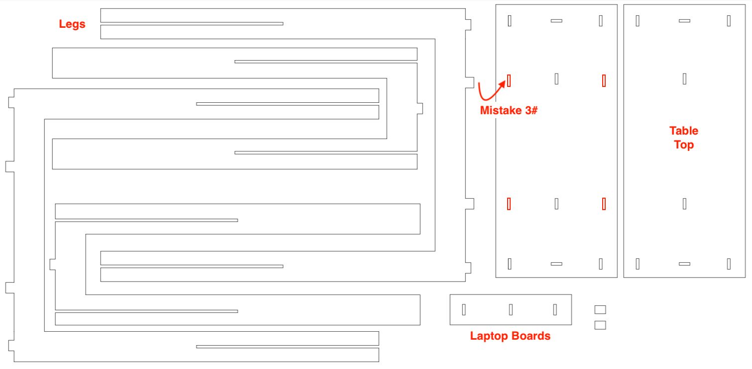
The cut-outs on the table-top were in the wrong orientation because I had not accounted for the 90° turn of the legs once assembled.
I realised this mistake after the first laptop board was completed, meaning I need to mill out only 1 more, so I removed it from the next design.
Misaligned Cut-outs
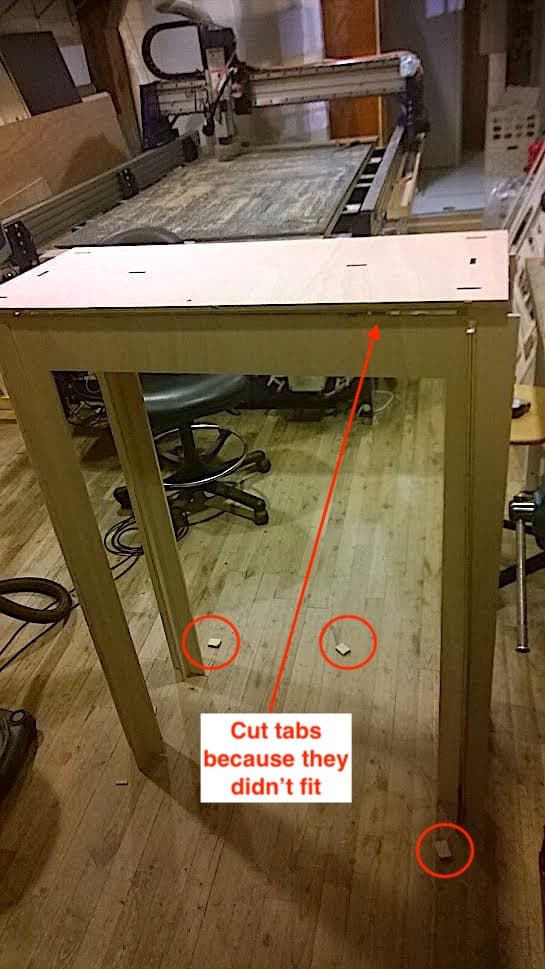
Here, instead, I was totally missing cut-outs for the tabs in the middle of the arched legs…
I only realised this mistake after the table was done, therefore this was the final design.
Too Late to Apologize
How The CCM-ing Went For Me
The material we had at our disposal was plywood, the dimensions: 1220x2500x9mm.
For this material the machine setting were determined as follows:
-
Kerf: if job is running with
centered on pathoption, then the kerf is radius of the tool -
Speeds & feeds: were determined by suggestion aka Emma & Michael told us what ideal settings would be and I followed those exact numbers.
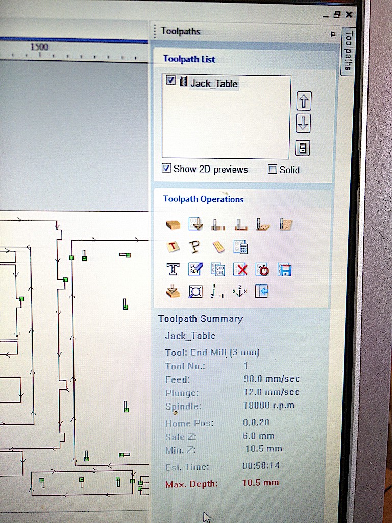
Going from design files to gcode is fairly simple using PartWorks (which is now outdated, the alternative is VCarvePro).
The two videos I linked at the top fo the page are also great to learn this process.
Machine Settings
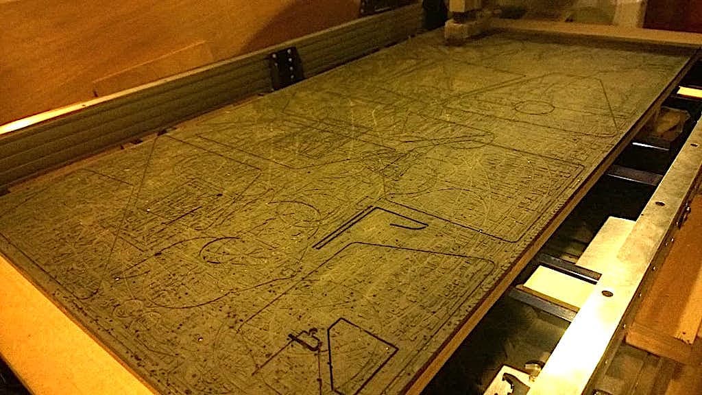
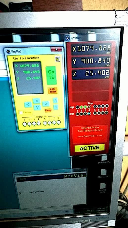
ShopBot Control
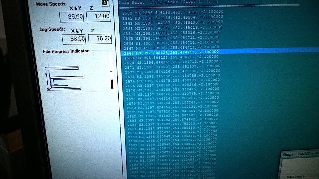
Running Table Job Progression
Fitting Tests
Before designing the table, I made a few, small, press-fitting test on some left-over plywood, to get the dimensions right (which I included in the downloads).
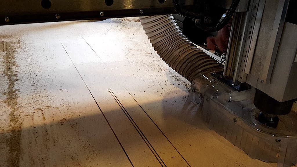
Because I decided to do these tests on the left overs from a previous student, as well as being my first ShopBot run, I did an air run to check that tests would fit within the borders.
Here is the ShopBot cutting out the tests.
Doing the tests turned out to be a good idea, because I realised a very important conceptual mistake I had made.
Benchmarking Cuts
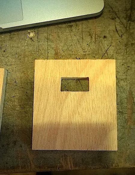
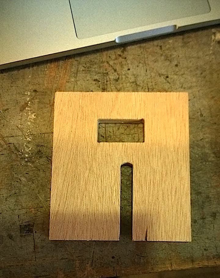
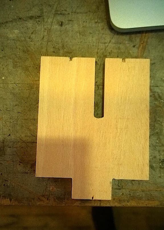
When I finally tried the fitting, I realised that the hole-fitting shouldn’t be the height of the tab, but rather the thickness of the material.
Fitting Test
Concerns
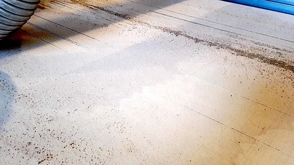
While milling out the table, on the first pass, the milling bit failed to cut into the material in certain areas.
I figured that, while I had taken into account different heights of the material on the edges, I hadn’t considered concavity or convexity caused by things like humidity, and basically the cut-depths were insufficiently deep
Cut Depth Fail
Fortunately, even though the cuts were uneven, on the subsequent passes the milling-bit cut through and there was only as small layer left to remove at the end of the job. There were some rough edges, but they were easily sanded down.
Gallery 
Pre-Assembly (with design error pointed out)
Laptop Stand
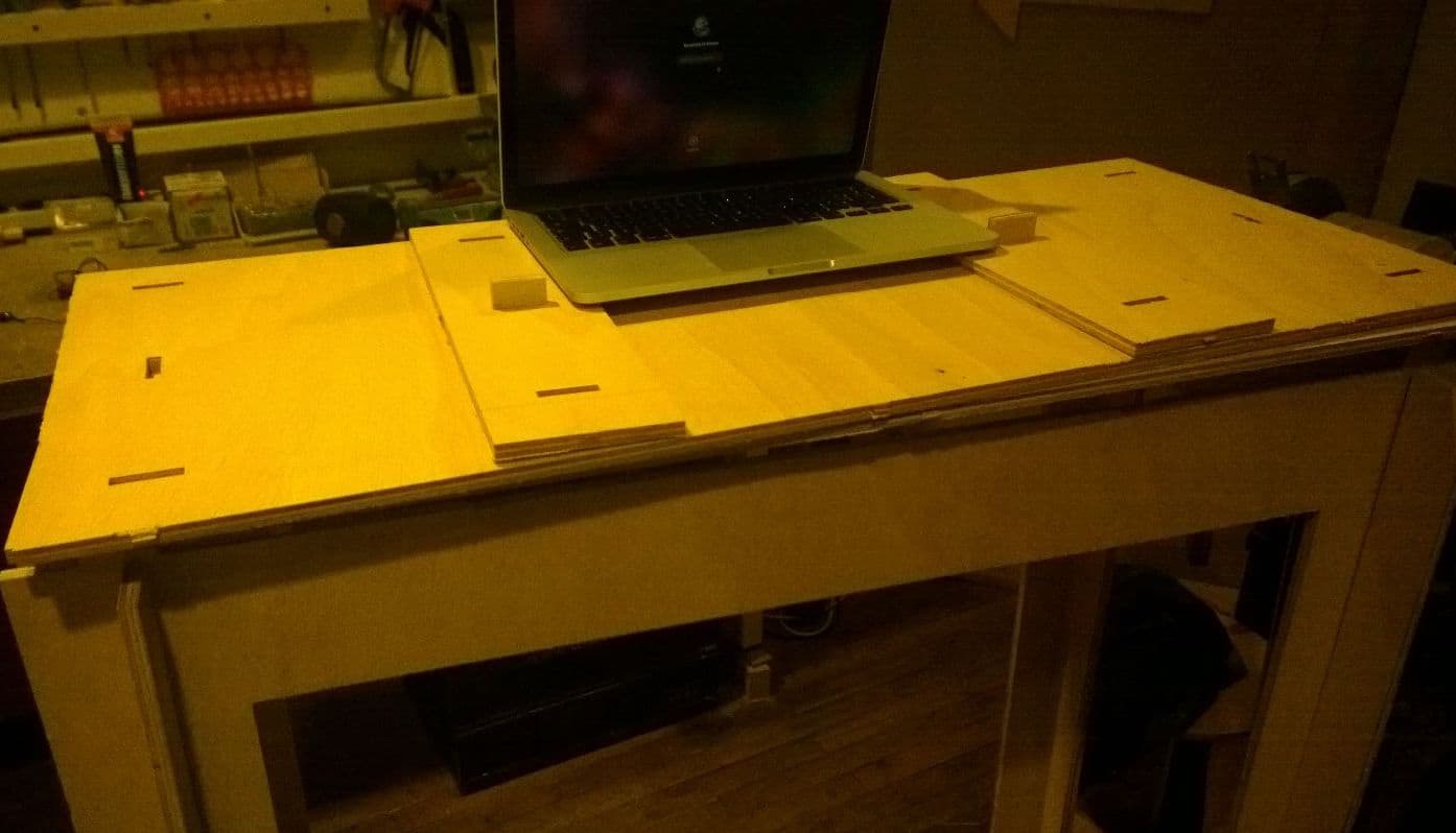
Hero Shot
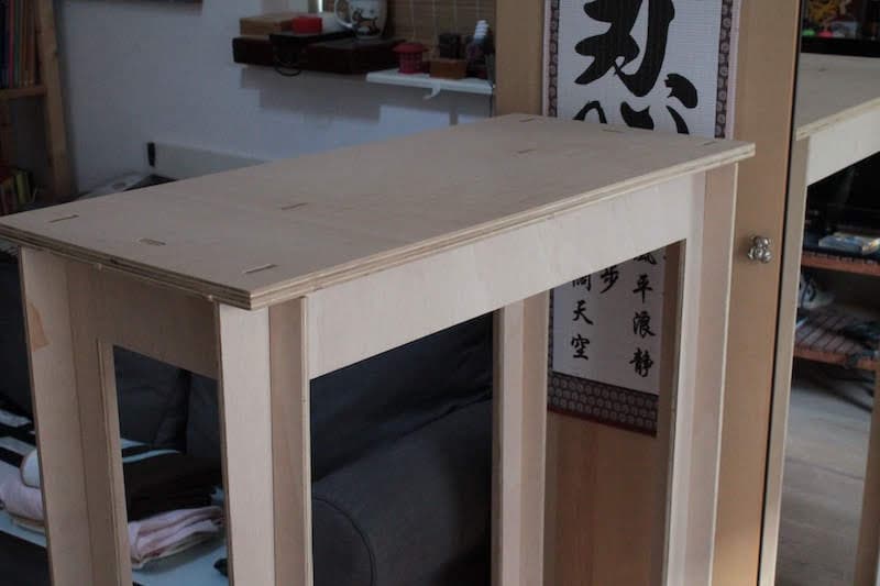
I decided that the laptop stand looked ugly and was cumbersome.
Download The Files
-> Fitting Tests
-> Full Table