12 - Output Devices
Changing the World
Tools & Assignment
 Updated for 2019 evaluation standards!
Group assignment
Updated for 2019 evaluation standards!
Group assignment
- Measure the power consumption of an output device
Individual assignment
- Add an output device to a microcontroller board you’ve designed and program it to do something
Learning outcomes
- Demonstrate workflows used in circuit board design and fabrication
- Implement and interpret programming protocols
Have you?
- Described your design and fabrication process using words/images/screenshots, or linked to previous examples.
- Explained the programming process/es you used and how the microcontroller datasheet helped you.
- Outlined problems and how you fixed them
- Included original design files and code
Nothing to copy from my old website :(
2019
I had never managed to finish the documentation for output devices in 2016.
So let’s start from scratch.
We would like to convey the ability of the system to learn, we can only achieve this by having rich user feedback, which an LCD screen will allow us to do.
To interface the user to the game I’ve decided to use a TFT screen, this will allow for enough interactivity to ensure the players is able to feel the game evolve.
One additional feature in this case is the touch screen, meaning that the majority of the interface can be relayed to to the screen, rather then having additional buttons or knobs.
The only two drawbacks are pin usage and memory, many of these screens require parallel communication, which would take up most of the pins.
However, unless we get ourselves and atmega2560 (here), we won’t have enough pins left to do communication.
Luckily there exist cheap SPI versions, which take up only 14 pins.
The only down size is that it requires 2 clock cycles to write to the screen, rather then only one.
So, we shall go for SPI.
As such my final choice of output device is: TFT 2.8” SPI LCD touch-screen
I got myself two of these, one for 13.51£ and the other for 10.99£
I discovered, later, that the 11£ option wasn’t touch screen, just a nice display… oh well.
These TFT screens are memory hoarders, no surprise there since it’s pretty well know that graphic-y things are compute intensive (think gaming PCs).
What we do know is that SPI screen run on Arduino.
Albeit they might do so with slow refresh rates, but that’s fine since we will only need it for a GUI, not animations.
We’ll think about the memory load later.
The TFT Screen
This particular type of screen is often driven by the popular ILI9341 PCB.
The one curious thing about this board is that, as can be seen on the it’s datasheet, it works on 3V logic.
ILI IC Datasheet - 3V logic
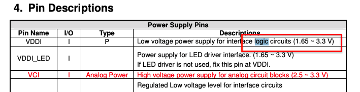
This means that it’s pins work by registering (input) pins as high (1) when the voltage on them is 3V
The Arduino uses 5V logic, and as such the voltage must be regulated.
We have 3 options in this case:
- Have ~10K resistors between the logic pins (used by many online tutorials)
- Using a level/logic shifter
- Shorting the jumper wire at the back of the LCD board.
Of these 3 methods, using the level shifter is the best option since it’s more reliable and will preserve the ILI9341.
However it’s also the least convenient since it requires and extra IC.
Shorting the wire at the back is the most convenient, but also the worst possible choice for longevity of the board, as the ILI9341 will run HOT  if the short is introduced.
A middle ground is obtained using the resistors, because they are readily available parts, one most likely has some spare to use, unlike for level shifters.
Adversely, they will be the ones getting hot, however they will withstand the abuse far better since resistors are designed with higher heat tolerances in comparison to the ILI9341, and they are cheaper to replace them.
Checking Facts & Statements
I wouldn’t want to make groundless assumptions, or make it seem like I do.
So, here are some numbers for operating temps for 0805 resitors and ILI9341:
This is of interest to us because we need to keep an eye out for for the IO voltage of whatever we will use to control the display.
Main guides followed on TFT screens:
- Arduino TFT LCD Touch Screen Tutorial (2.8” ILI9341 Driver) also for ESP32
- How to create a simple Touchscreen GUI || Arduino LCD & Touchscreen Tutorial
Choosing the Microcontroller
I mentioned earlier that the TFT displays are memory hoarders.
What I actually mean by that is that the libraries required to run them are large to load into the limited memory of AVR controllers.
For the ATmega328P (datasheet) which is what runs the Arduino, the specs are:
- 32K Bytes of In-System Self-Programmable Flash program memory
- 1K Bytes EEPROM
– 2K Bytes Internal SRAM
Now, when I say size is an issue, I don’t mean I don’t have space to load the entire sketch (which may be the issue on other devices) but rather it’s reflected by the FPS, or rather the refresh rate of the screen.
This reflects most on the SRAM, meaning that the lower it is, the slower the refresh rate.
With our use for the screen, as a UI that is, a fast response isn’t strictly necessary, but too slow would be a problem.
If we take a look at the attiny84 (datasheet), we can see that we get the following:
– 4K Bytes of In-System, Self-Programmable Flash Program Memory
– 256 Bytes of In-System Programmable EEPROM
– 256 Bytes of Internal SRAM
This IC suddenly appears seriously limited, we will need the ATmega328P…
The above statement should tickle your FabSenses™, that’s because the popular Satshakit & FabKit uses this AVR.
The Satshakit is particularly interesting for it’s superior interface with the Arduino IDE, but we should take a rain check.
Thou Shalt Not Copy-paste The Satshakit
~ Neil Gershenfeld
Since that is the holy decree, I actually decided to not even look at, or cross reference either of those kits, when creating my board.
So, what you see below, is entirely my work, wire for wire, with the help of these three tutorials:
- Minimal Atmega328P on a breadboard
- From Arduino to a Microcontroller on a Breadboard
- Building an Arduino on a Breadboard
I hope, and think, these is reflected in the differences in design between the two board.
Of course, certain elements will remain identical in both designs. Particularly, the basic components, but to be frank these aren’t original to the Satsha kit or Fabkit, but most likely the 2008 Arduino guide I’ve pointed out above.
Design Notes
Firstly, it’s important to point out we don’t want to mimic original Arduino, only use the same controller.
In my case I will need to re-order the pins, or find some other solution, so that I can have a simple plug-n-play interface with the TFT screen. The general purpure nature of the AtMega will be a second thought
Secondly, I only have 0805 components for resistors and capacitors, which aren’t part of the Fab inventory.
Lastly, the design is done in KiCad.
The libraries needed to get the full functionality are:
I know there exists a faster ILI9341 library, namely ILI9341_due, as replacement for Adafruit_ILI9341, but I’ve not figure out how to make it work as of yet.
Getting Started With The Atmega328P-AU
Firstly, I will recreate the circuit seen here.
In the video, the package of the 328P is PU (pinout, we can cross reference to our package with this pinout sheet
5V Logic Levels
The ATmega328P datasheet states that the atmega can be run on two modes, 20mA or 10mA.
In the first instance, 20mA the output voltage is 5V, with 10mA its 3V.
ATmega328P Datasheet - DC characteristic logic
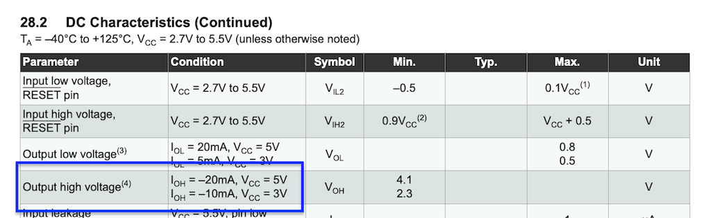
I’m going on a hunch here, but my guess is that the 10mA version is less powerful then the 20mA option, considering Arduino went for the latter option.
So, even though I could drive the TFT screen natively, for the sake of maintaining the same performance I’ll stay clear of it.
Having made up my mind, we need to worry about the 5V logic levels, but that comes later, when we design the connection to the TFT screen.
PCB Design in KiCad
In this case the design isn’t very different from the others we’ve made.
One thing to keep in mind is that we will have many unconnected IO pins, and we also need to keep in mind this board will need to communicate with the CapSense board from week11.
Therefore a better design choice is to have only the vital components on the board, and include pin headers for later usage of the unconnected pins.
Following the perviously mentioned guides, the schematic looks like this:
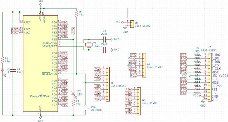
Interesting to note, is the header which has 10k resistors on every pin.
This will act as the aforementioned level-shifter for th TFT screen, however it’s clear from this schematic that we won’t be able to route every connection as seen above without some form of 3D connections.
I don’t have double sided copper clad boards, therefore the best way to create this board is to design it as a small add-on shield.
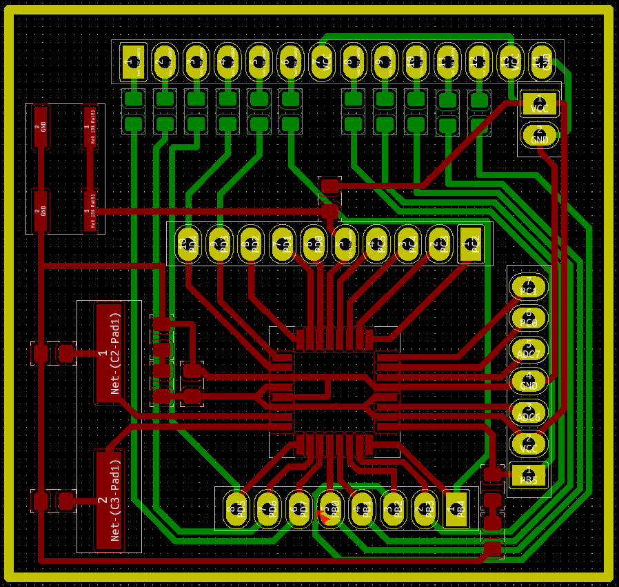
The designs makes it seem like the board will be two sided, in fact I will mill the two parts on separate boards and use the center holes to connect them.
Also, the pads are oval in this design (since I learned my lesson from trying to solder headers in week11) this can be achieved in KiCad by opening the preferences for the footprint of each pad and changing the shape from sqaure to oval.
I don’t know how to apply this operation to all headers at once (couldn’t find it), so I did it manually for every. single. footprint.... Which took some time.
There is an arrow (aka an error in the check) at the bottom of the routing design. This is caused by a small trace passing through headers, it’s the only one and I couldn’t do without it, but I designed intentionally and didn’t expect it to be a problem even if it broke the clearance rule.
Design Choices
Looking back I realize that this wasn’t such a good design. It would have been better to simply design a small addon board the TFT headers that connected to the screen and had the required connections, dump the idea of using it “shield like” and using dupont connectors. Oh, and bought some female 2.54 mm headers.
Milling
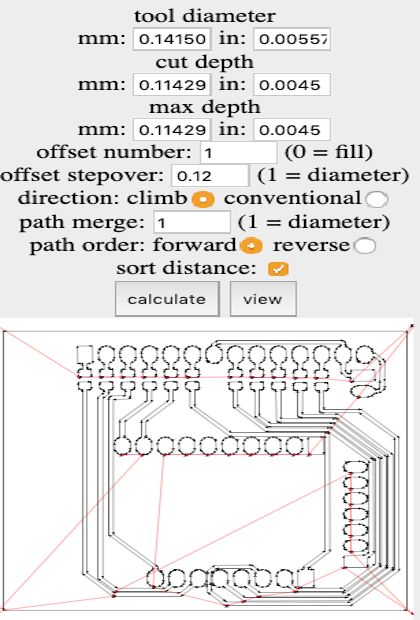
We can export the file as an .svg and load it into my custom made mods program with the following settings:
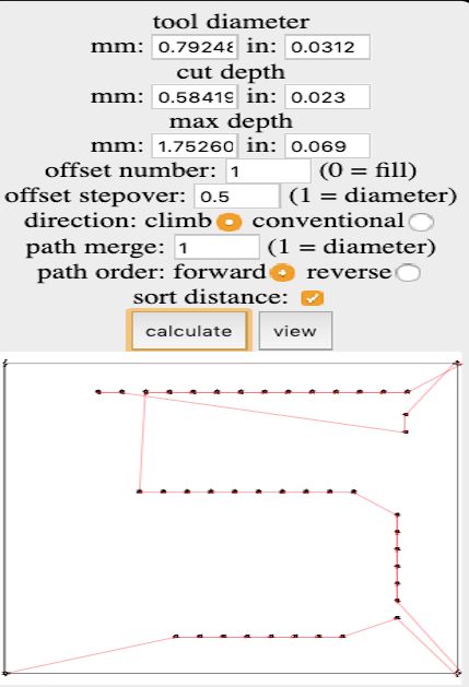
Same settings for level shifter board.
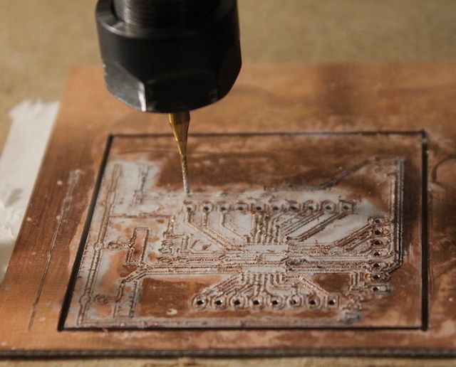
Moving over the job to bCNC, this is our final result for the board:
Stuffing
If I had a challenge for week11, this week was hell.
The heat from my cheap soldering iron, which has a joke knob for heat control, just melted away the glue keeping the tracks attached to the board, in certain parts of the board I had to do some serious surgery to keep the board alive, but in the end I managed.
In terms of debugging though, it took me longer to fix the level shifter board, which because there are so many 0850 components close to each other, whenever I fixed a short in one trace I’d create one the other.
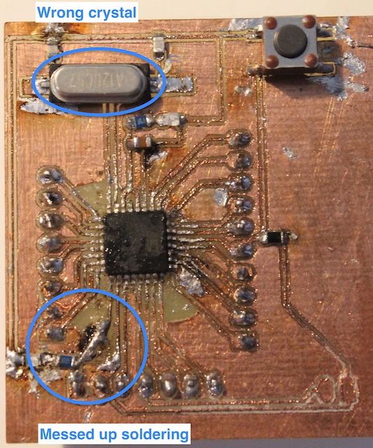
I pointed out the various mistakes I did.
For the board itself I soldered on the wrong crystal type (12 Mhz instead of 16 Mhz, I had both laying around) but since I had already applied nail polish by the time I realized, the damage couldn’t be undone. The only issue this will cause is slightly slower refresh rates.
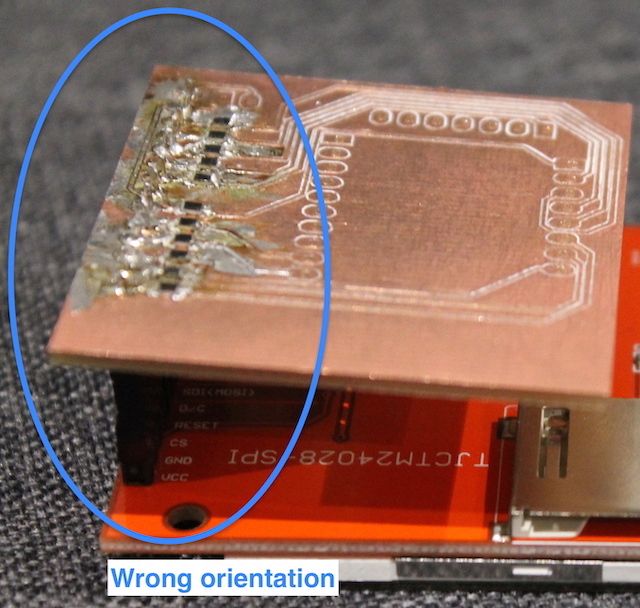
In the second image you can see I soldered the level shifter board on the way I wanted to, but realized that the board was actually mirrored, so (as can be seen in the hero shot) it will be actually sticking out of the side.
Programming
Programming atmega328p board to control TFT screens is a fairly straightforward job, thanks to the huge amount of resources on the internet.
Required Libraries
As mentioned earlier our screen uses the ILI9341 IC to control the screen, luckly we can relay on these two libraries :
-> Adafruit ILI9341 Arduino Library
You can download them as .zip and add them to your arduino IDE by
Sketch->Include Library->Add Zip Libarary
Getting started
Once that’s done, getting started is as easy as open the graphicstest example program:
File->Examples->Adafruit_ILI9341->graphicstest
and doing a small amount of modifications.
We comment out the SPI.h import.
// #include 'SPI.h''
#include "Adafruit_GFX.h"
#include "Adafruit_ILI9341.h"
We define the pins to which the TFT screen is connected
// For my shield, these are the default.
#define TFT_DC 8
#define TFT_RST 9
#define TFT_CS 10
// SPI
#define TFT_MOSI 11
#define TFT_MISO 12
#define TFT_CLK 13
Adafruit_ILI9341 to write to the screen whit the given pins
Adafruit_ILI9341 tft = Adafruit_ILI9341(TFT_CS, TFT_DC, TFT_MOSI, TFT_CLK, TFT_RST, TFT_MISO);
week9 andweek11 for more setup info):
Sketch->Upload
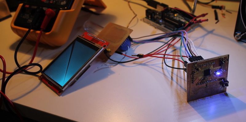
This, is the final result:
Hero Shot
Further Use
I developed the GUI program which goes far beyond this example, but I think it’s outside the scope of this week, since it’s intertwined with input devices and the learning algorithm and I can’t really decouple those aspect, therefore I will document the code on the final project page.
My main resource is the GFX pdf guide
Download The Files
-> KiCad Design Files (Also Contains Design Files For CapSense Board - week11)