5 - Electronics Production
This Week I Wasn't So Lucky... Cries
Tools & Assignment
 Updated for 2019 evaluation standards!
Group assignment
- Characterize the design rules for your PCB production process
Individual assignment
- Make an in-circuit programmer by milling the PCB, program it, then optionally, trying other processes.
Learning outcomes
- Described the process of milling, stuffing, de-bugging and programming
- Demonstrate correct work-flows and identify areas for improvement if required
Have you?
- Shown how you made and programmed the board
- Explained any problems and how you fixed them
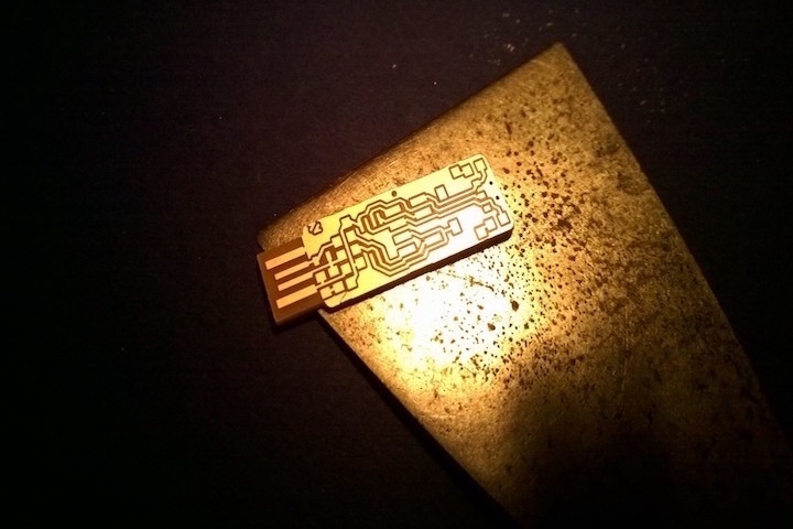
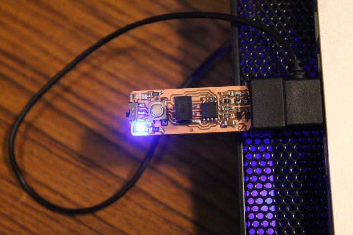
- Included a ‘hero shot’ of your board
(Copy of my 2016 website, with spelling corrections :)
Preamble
Since I was about 15 I begun to build my small soldering / electronics station in my room; which I mostly used to disassemble old electronics & repair the broken electronics (such as phones) of friends and family.
However I had never soldered “surface mount” components but only “through holes” which is much simpler. I had also never used the milling machine
Our Fourth Lecture
I was sick for this lecture, so I had re-watch it at home. During this lecture Neil went through the processes of making PCBs (both industrial and through the use of a milling machine), the components we are going to use and how that applies to this weeks assignment.
Making The ISP - Preparing The Copper plate
Note: For the process to go well the copper plate must be completely flat, otherwise it will not cut out the copper properly. The copper plate is mounted on an acrylic bi-layer which is made to fit on the Roland Modela and to be fixed with two screws. Between the first layer of acrylic and the copper plate we want to cut out there is another copper plate which we call “Sacrificial layer”, which is needed to prevent damages to the acrylic, and is changed roughly bi-annually. The copper plate is fixed onto the sacrificial layer with the use of double-sided tape.
Sacrificial layer before applying new double-sided tape
The Process of Using The Small Milling Machine (Hardware)
I. Turn on the machine by pressing the on button
II. Set the machine in “View mode” by pressing the view button.
III. Replace the mill-bit with the one you will use for your PCB (1/64 to make traces; 1/32 to cut out).
This must be done carefully:
the small hexagon-socket screw, at the base of the rotary axis of the milling machine (only on one side), will loosen the mill-bit which you must hold at all times to avoid it from falling and thus getting damaged.
The reverse process is done to insert the new, desired, bit. (Make sure that the bit is inserted deep within the rotary axis at first, to make sure it does not crash against the copper plate once it is taken out of view mode)
IV. Insuring that the mill-bit is well fixed to the rotary axis, the machine is taken out of view mode, then by pressing the up or down button we adjust the height of the z-axis to roughly what we need.
V. We un-screw the mill-bit once again to adjust the height to exactly what we need, remember to accompany the bit until it touches the copper plate (do not let gravity do the work, this will damage the bit).
The Process of Using The Small Milling Machine (Software)
I. Turn on ubuntu computer.
II. Open Terminal; type and enter fab. This will start the fab module application.
The Terminal
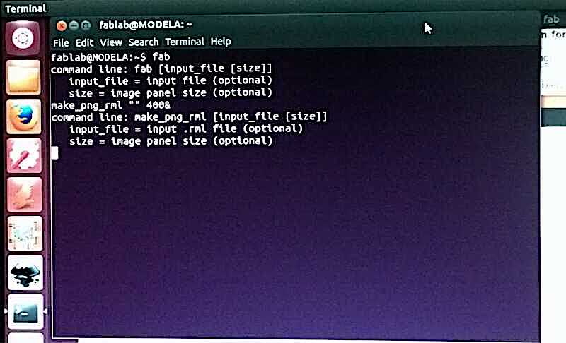
Opening the fab module through the terminal using the command fab
III. Select image file format, for us .jpg, and machine model, for us Roland Modela => Select make_png_rml, this will open up a new window
Fab Module First Screen
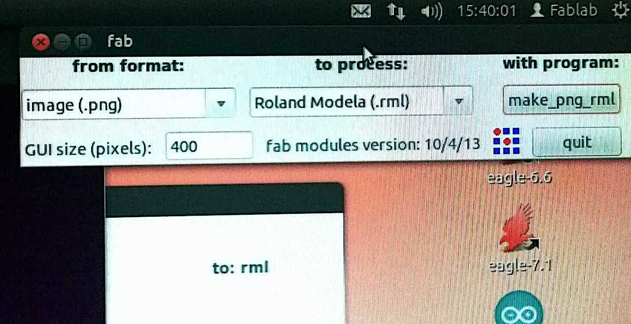
Select the image format & the the machine you will be using.
III. Load the png file from the FabAcademy folder; our choice was between Andy & Zaerc models (I chose the latter, preferring to have the LEDs)
Fab Module Second Screen
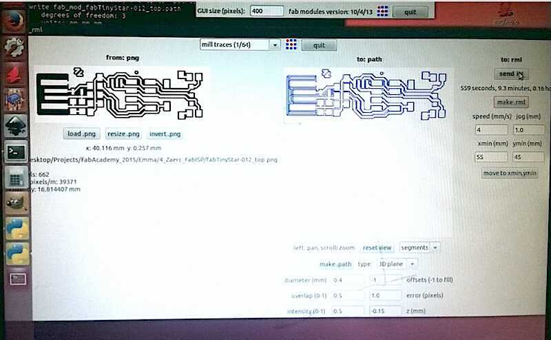
Load the png -> Make path -> Select parameters -> Move to Xmin/Ymin -> make.rml -> Send it!
IV. Select “make path” and adjust the different parameters to fit your preference, then once again “make path” to apply the changed parameters.
V. Then you must select a xmin and ymin value as the starting point for the mill-bit on the copper plate as preferred by the user.
VI. Finally you can select make .rml, this will show you the estimated amount of time need, as well as an option Send it! which once pressed will send the file to the machine which will start cutting out your desired design.
Notes
1# Its a good idea to press view a few moments later you sent your rml, to check out how the cut/trace is going.
2# After you are finished cutting out the PCB, prey it up with a spatula to remove it from the rest of the plate.
PCB removed with spatula
3# Remove the double sided tape from your PCB cut-out.
4# Close the wooden enclosure of the Roland Modela to decrease the sound produced.
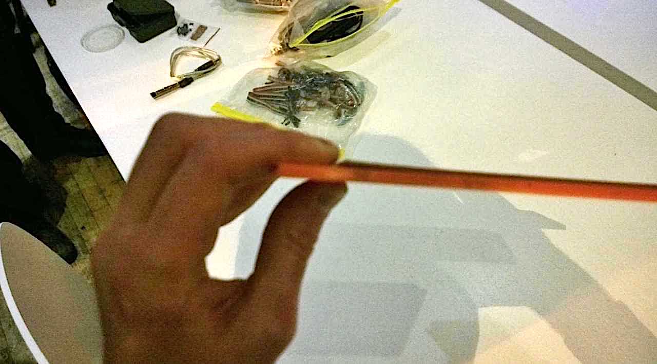
5# In the 10ish minutes it takes to trace out the circuit, go hunting for components!
Its a good use of the time.
List of components
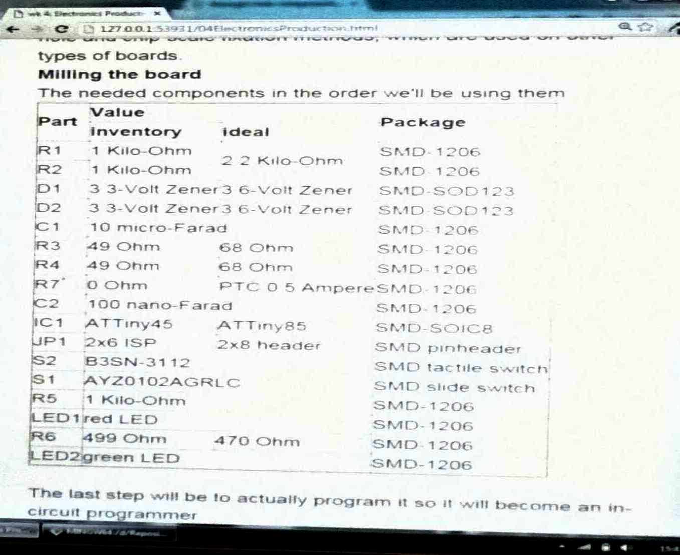
List of components need to stuff the ISP
How It Went For Me
Well, I failed on multiple occasions.
It took me five tries to make a proper ISP.
On my first try the tracing went great but for the cutting out I didn’t screw the 1/32 mill-bit tight enough, this made it go loose during the cutting obliterating the bit and cutting into my ISP this was QUITE scary.
Result of not screwing the mill-bit tight enough
(I always kept the offset at -1 to make sure all the copper is removed and the error at 1.0)
On my second try, after getting a new 1/32 mill-bit, I managed to cut out the ISP and the traces seemed beautifully shiny.
I discovered this was not such a good thing, it meant the copper had not been cut out properly.
On my third try I started again to trace, but the traces were again not deep enough, so I attempted to quit the job… This failed since I didn’t know the proper procedure.
Cicilia came to my rescue and thought me how to quit a job:
-> Pressing up and down at the same time on the Modela
-> Opening the terminal on the computer
-> Pressing control-c
-> pressing up and down at the same time once again).
I gave up for the day and went home with a few “not finished ISPs” to practice my soldering.
Cause of failure identified
 Sacrificial plate not flat = did not trace out the copper plate properly
On my fourth try on the next day I removed the copper plate and placed new double sided tape on the sacrificial layer to make sure it was perfectly flat, I also increased the depth from the standard -1.0 to -1.5.
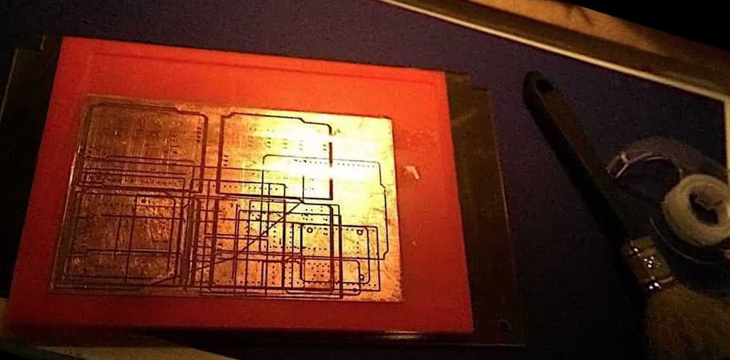
I started the job and once again the traces were not deep enough right from the start, so I quit the job and increased the trace depth from -1.5 to -2.0 and I traced over the existing traces, this worked out great and I managed to make my first perfect ISP PCB.
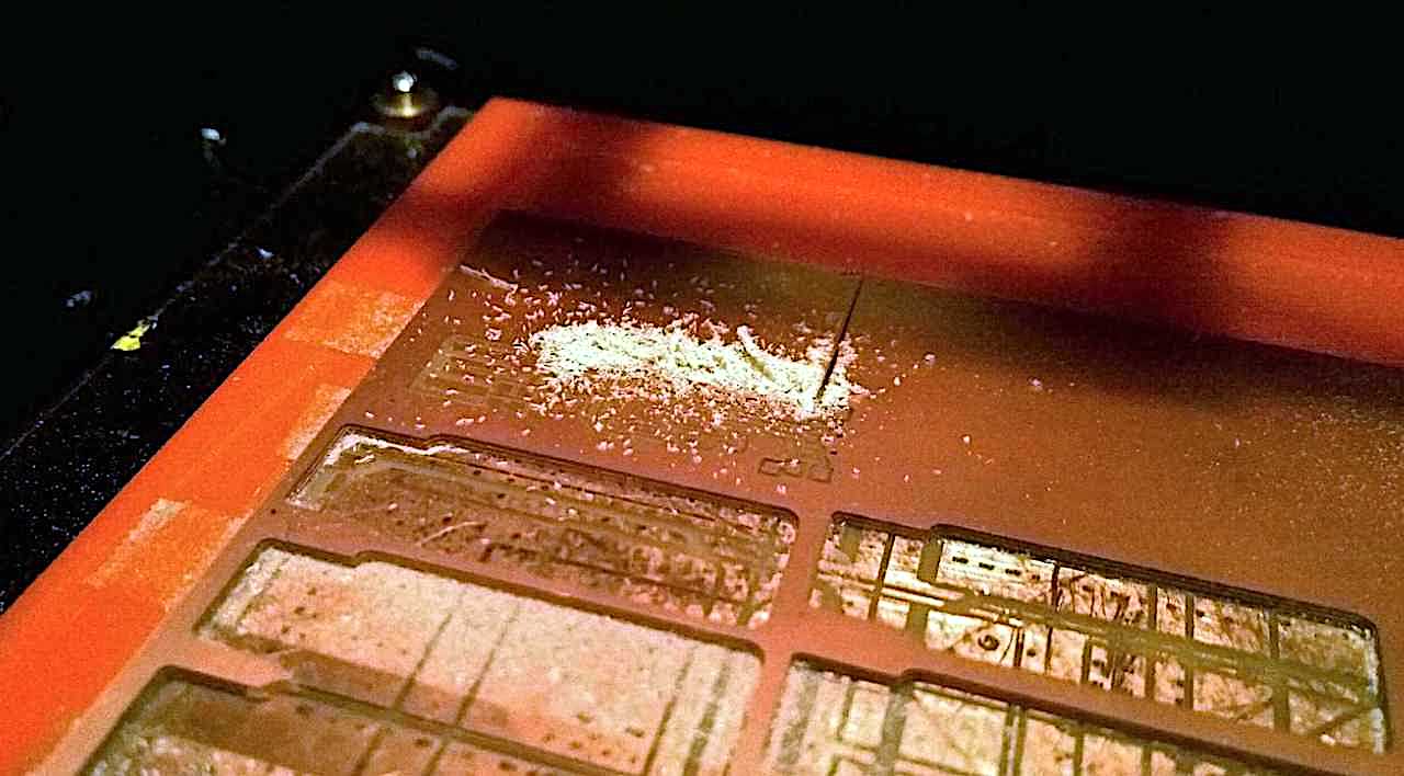
The Milling Machine Working
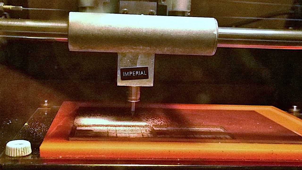
The milling machine tracing out the layout for my ISP
Sadly while I was stuffing it I created a short which I could not find and so I had to make my fifth attempt, which worked out from start two finish without any hick-ups (Offset = -1, error = 1.0, depth = 2.0), and would later become my final ISP.
Stuffing
I followed closely the instructions from Zaerc, this made it quite simple.
At first I took a few unfinished ISPs from previous years, desoldered the components and put them back, I did this at home.
I also desoldered some other components from old electronics and tried soldering them on, just for practice, since I never had practice with surface mounted components.
With my first ISP, I followed what Zaerc did to the letter, however I created a short and was unable to find it, and I knew it would have taken me longer to find it then to make a new one, so I did (as mentioned previously).
The components had to be fished from a huge array of small shelf’s, which was rather challenging at times.
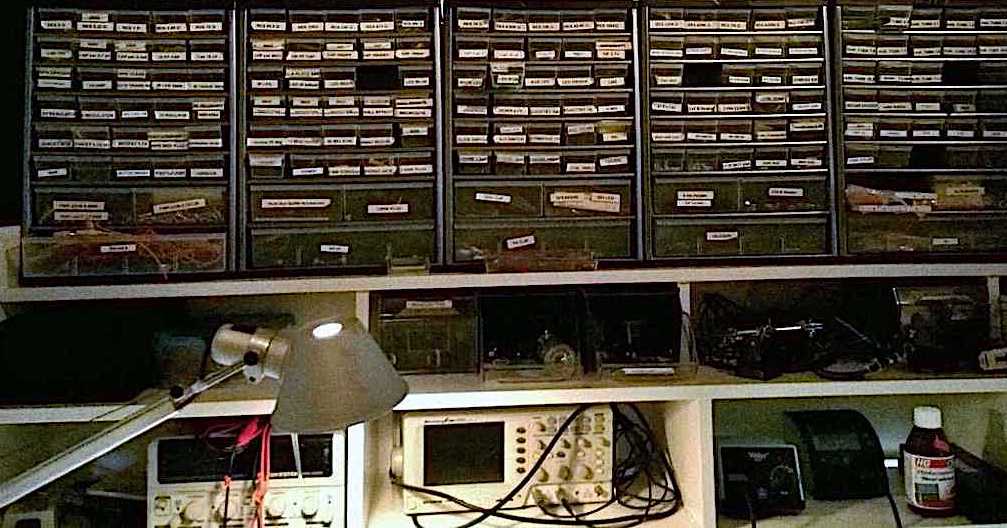
Drawers with all the components
On my second go, I placed the solder on the “cardinal pads” first, then placed all the components, then put the solder on the other ends.
This was a mistake, I did this in attempt to use less solder, thus decreasing the chances of creating bridges, however I discovered there is such a thing as under-soldering, and while I had no bridges (since I checked constantly with a multimeter) some components were not even connected to the copper plate… Finding all the missing connections took a while.
(I also switched the green LED with a blue one, which makes no difference but looks better in my opinion.
I then switched the location of red and blue LED, this was a mistake, but since the red one is on most of the time, this was a productive mistake; I also got the orientation of the LED wrong, in my defence the blue LED had a counterintuitive label).
Programming
Emma aided Marije and I in the programming of the ISP, she sent us an additional tutorial and download page which helped us set up our macs for flashing the ISP.
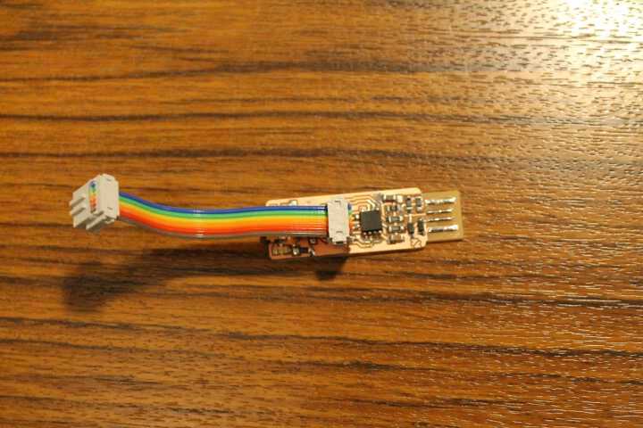
We used Emma’s ISP to flash our ISP, by connecting them through the 6 pin-connector.
6-pin connector
Following Zaerc’s tutorial everything went pretty smooth. (Mac users also need to install XCode).
2019 Note
In my original documentation I wasn’t kind enough to share the tutorial mentioned above, in 2019 I would use this tutorial, which uses an Arduino to program the ISP, to fill the void in my documentation instead.
Seeing I don’t have Emma’s ISP handy to replicate exactly the results :)
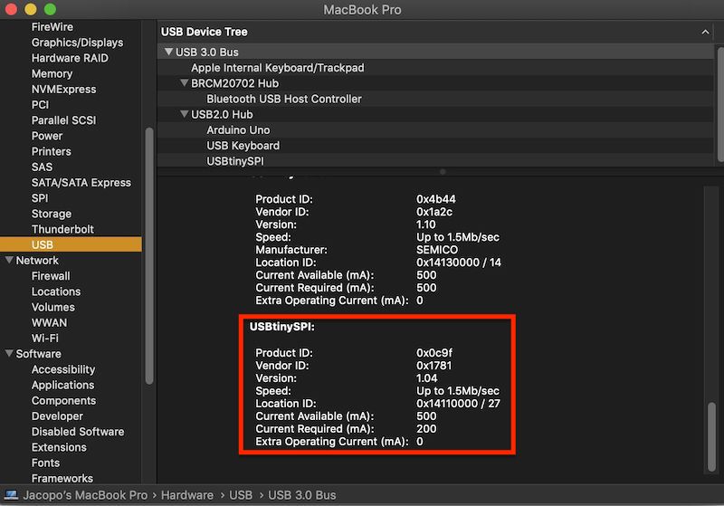
The check that the programming was succesful in MacOS
Apple menu->About This Mac->System Report..->USB(underhardware)
Scroll down and you will find:
Tips
-> Place an eye-lens on the front of the camera of your phone to get great pictures of small components.
Magnified Photo of Components
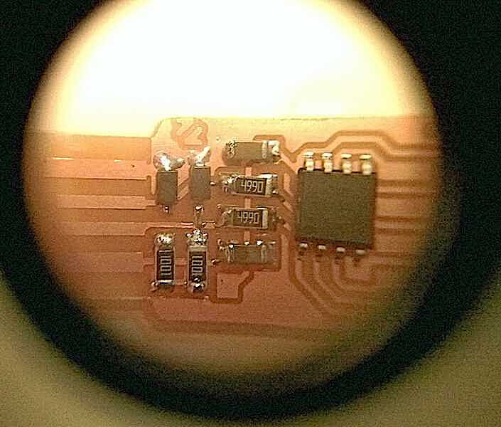
An early photo of the components being soldered onto my ISP (Using the trick of the lens over my phone’s camera)
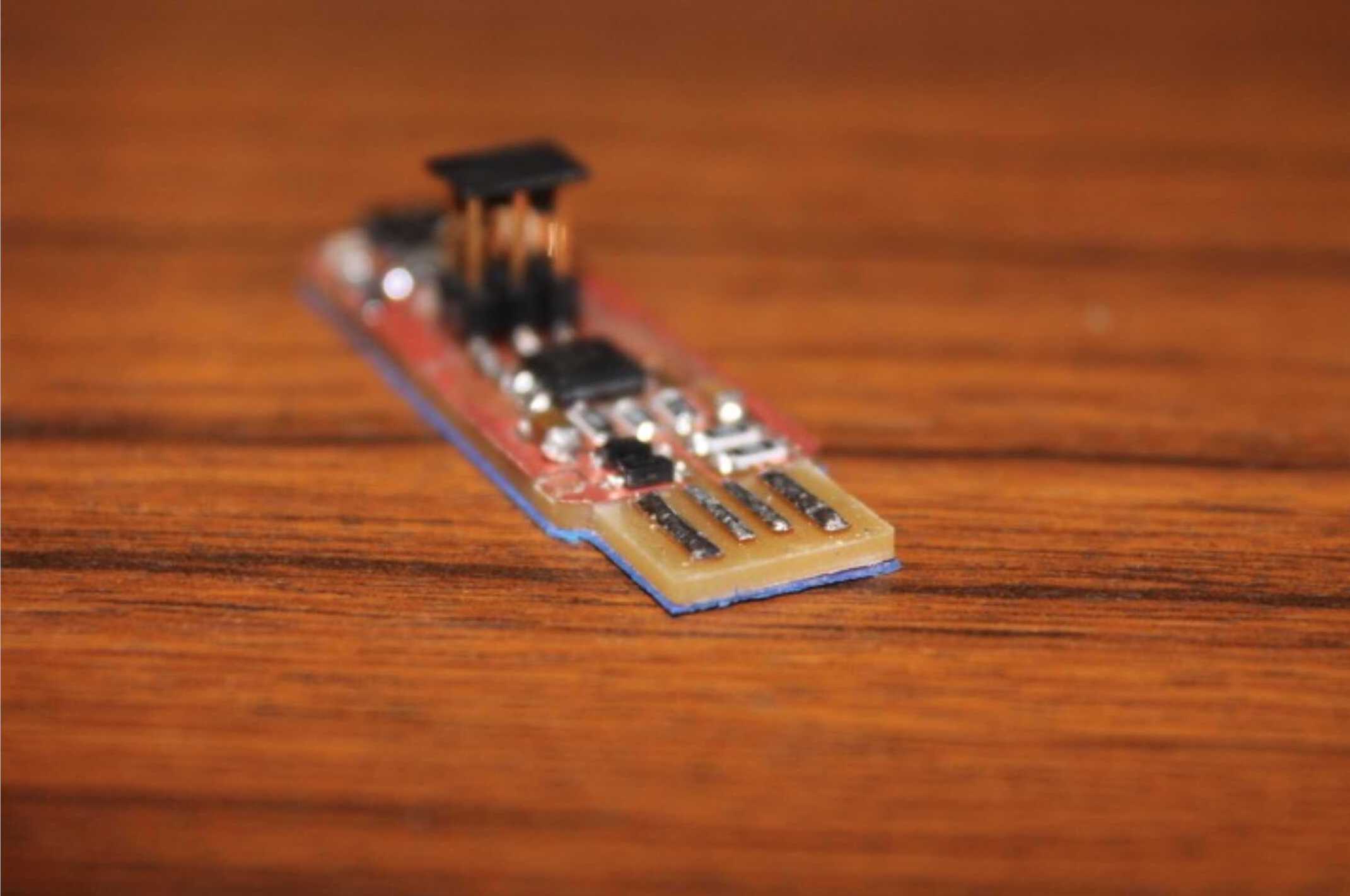
-> Cover backside of ISP with cardboard to make it stable within the USB port.
ISP with cardboard layer
2019
The 3018 CNC Milling Machine
In my quest to mimic as many of the functionality of a fablab at home, I purchased a cheap, yet functional, CNC machine.
It’s official name is 3018 CNC, which is also a description of its working area, 30 by 18 centimetres.
I will use this to etch my PCBs, ideally it takes the place of the Roland Modela used in FabLabs for Fab Academy. However, at heart, it’s closer to a Shopbot.
My particular 3018 is the SainSmart Genmitsu CNC Router 3018-PRO DIY Kit.
It comes in the form of a kit, meaning I had to assemble it all by hand, which is pretty straightforward following the instructions on their wiki page.
-> Sainsmart 3018 Pro CNC Kit Assembly YouTube Video
This whole process was quite lengthily but straightforward and fun, I’ve not much to add on-top of the excellent video guide above.
Honghao’s Criticisms
Now, in one of the many links from the schedule this week (Electronics Production), there is a project page which specifically talks about using this 3018 CNC to do milling -> Honghao Deng
He points out several shortcomings of this machine, specifically:
“It works, but besides accuracy you also trade in your health, safety and time.
Here is how the test mill came out after a few hours of fine tuning. It works.
Few things worth point out, here are the reasons for why one should spend more money on a Roland:
1. no cover == no noise/dust protection. Very bad for both yourself and your neighbours. (never start it 2 am)
I don’t understand why they have to build the machine with aluminum at a price $200.
A machine at this size, I think it should come as plug and play with plastic cover and plastic structure.
Why there aren’t someone doing it.
2. Mill platform and x,y moving plane is not perfectly parallel. That comes from hand measured hinge positions on the 80/20. Very poor design.
3. No feedback, the motor is x, y, z motor is blind controlled by the grblControl software without knowing it’s physical boundary.”1
My Counterarguments
I understand and appreciate many of the points made above however they are, fundamentally, surmountable.
Point 1 & 3
The basic issue outlined here is the absence of an enclosure & limit switches on the axis for homing/absolute 0 point.
Fortunately we have access to a Fablab, and here enclosures for machines have been milled/laser-cut plenty of times.
To that end I point you to this excellent guide:
-> Instructables “Upgrade Your CNC” for 1610, 2416 or 3018
Which takes your CNC from cheap to a serious workhorse capable of milling even aluminum. While also adding many security features which Honghao had not commented about, such as:
- Emergency STOP button
- Electronics enclosure
- Manual control knobs
Point 2
The axis alignment is a delicate topic.
It’s well understood amongst users of these CNC’s that, with the original 3018 model, much care must be taken when constructing the frame to ensure the axis are parallel.
Meaning this point amounts to an assembly mistake, and the user is at fault (and not using a angle tool to align the frame properly).
Having said that the “pro” in the name of my version of the machine exactly aims to fix this issue, but removing the risk of misalignment by having a different build.
Time
Not an independent point, but more scattered around.
Honghao mentioned that the kit should come pre-constructed, which besides creating serious shipping concerns (keeping in mind these things are posted from China), removes much of the fun and enjoyment/learning experience of owning such a machine, while decreasing the cost.
If we really cared about time saving, would we really be milling our own PCBs?
Instead of ordering them from production websites (eg. jlcpcb) at a fraction of the cost of the entire machine?
Even then, doesn’t saving time justify scrapping PCB production and just buying directly the arduino that inspires many of our circuits?
At heart the 3018, with it’s replicable, mod-able and open-source design is far more aligned with the “make (almost) anything” philosophy of the FabAcademy, than a big shot machine like the proprietary Roland Modela.
“Plug & Play w/ Plastic Cover & Structure”
There is a simple answer to that, it has been tried, but when it comes to CNC Mills, rigidity is king.
Even if there were pre-built, plastic CNC mills out there at the 200$ price point, people would still opt to go for the aluminum kits without cover, simply based on end-result and feed-back.
Also, why pay the extra money for a plastic cover (+shipment of extra weight) when you can make your own?
Moving Onto The Usage
One caveat of using non-standard equipment is, of course, the fact I can’t use Fab Modules.
Well, I didn’t try it. However, assuming connecting my CNC to the Fabmodules and trying to start the job using the standard Roland MDX 20 configuration sounds like a BadIdea™.
The generated tool path could be useful though, particularly if I can figure out how to output it as .gcode file (I’ll get back to this later).
First we need to think about controlling the machine.
Updating The Machine
This machine is meant to work with Windows, or rather, most instructions are Windows based. However I am a Mac user. Thankfully many of the parts can be replaced with Linux/MacOSx alternatives, which I will outline here:
If you’re on Windows, the sainsmart wiki has video tutorials and download links for all required upgrades.
GRBL Upgrade for Mac
GRBL is:
“An open source, embedded, high performance g-code-parser and CNC milling controller written in optimized C that will run on a straight Arduino” 1 -> grbl wiki
This software runs the 3018 CNC, and we wish to have the latest version.
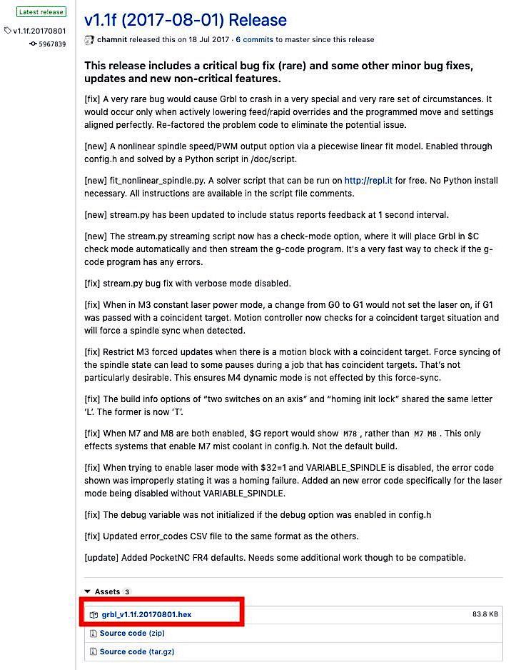
First thing to do is download the latest release from their Github page -> GRBL Releases Github Page
We scroll down until we find grbl_vX.XX.YYYYMMDD.hex which, as of 19th of April 2019 is grbl_v1.1f.20170801.hex (83.8 Kb).
After this, the official instructions will tell you to connect your CNC to your PC and use Xloader to flash the .hex file to the controller on the machine.
To those of you who have experience with programming AVR microcontrollers, a bell should be ringing right about now.
Indeed Xloader is just a wrap around AVRdude, which is:
“A utility to download/upload/manipulate the ROM and EEPROM contents of AVR microcontrollers using the in-system programming technique (ISP).”2
Which should be familiar to all FabAcademy students/instructors.
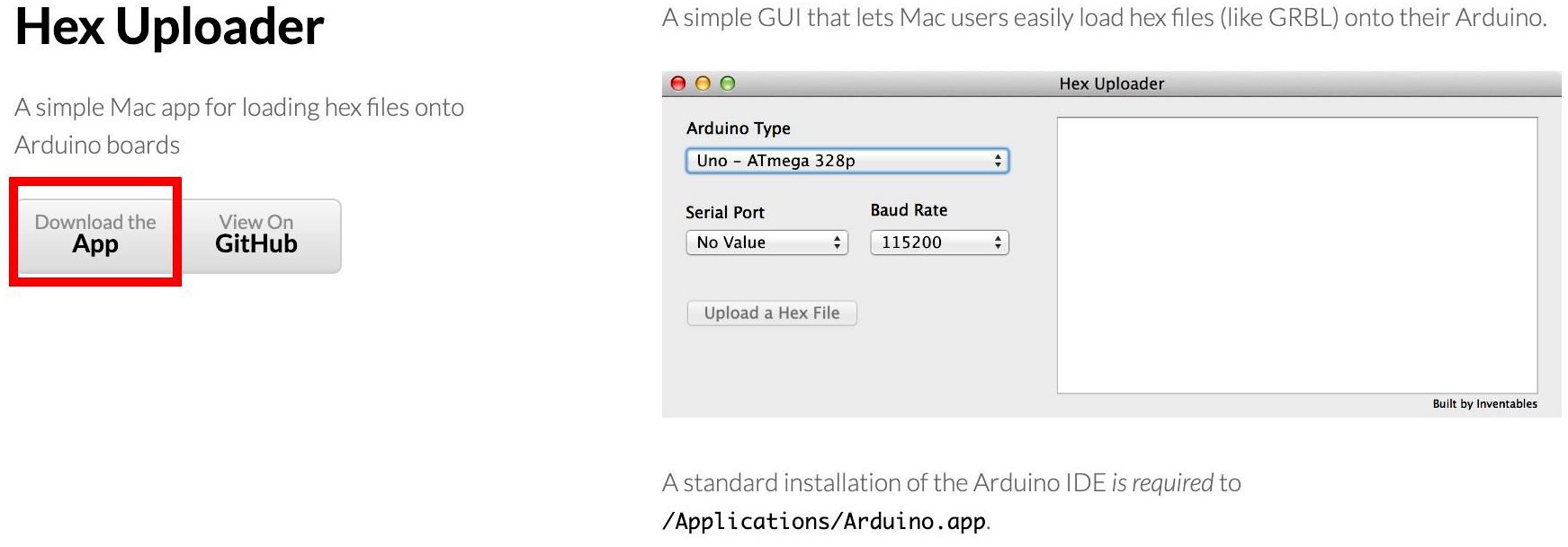
Fortunately there exists a MacOS alternative for Xloader which is called HexUploader
Which does the exact same thing (if you’re too lazy to use AVRdude, which to be honest we all are :)
Method 1: HexUploader (spoiler alert, it won’t work)
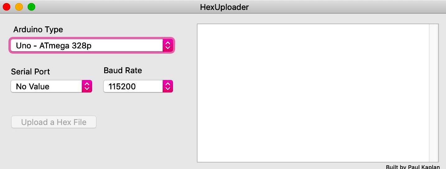
So, we download the app:
We unzip the downloaded file HexUploader.zip and the app is ready to run.
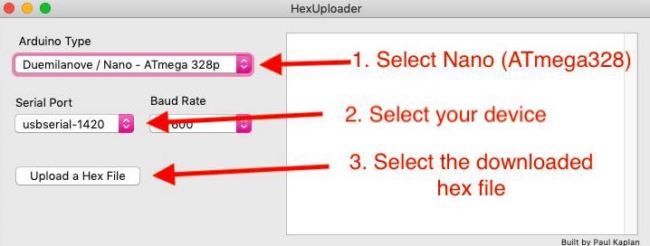
The original instructions for windows have the following screenshot:
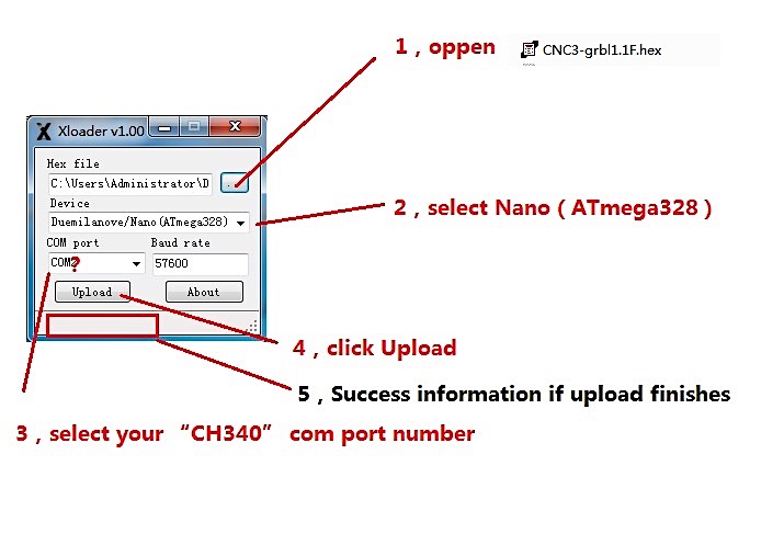
We are going to do the exact same thing, except on HexUploader, and using the .hex file we just downloaded.
First we need to connect the CNC to the PC using the provided USB cable, in the case of my CNC it’s a USB to miniUSB cable that plugs into the main-board of the machine.
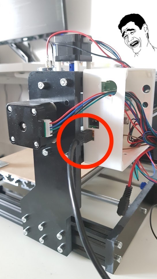
Once that done we open hexUploader and set the parameters as in the instructions, hit upload & select the .hex file we downloaded and wait for the magic to happen:

And everything will work perfe - ooh wait…
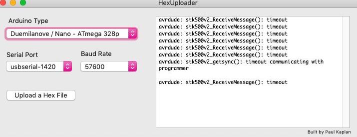
After doing some research it seems the problem is that “the AVR is not executing the bootloader”.3
The solution is to hit the reset button on the board, but here they talk about Arduino IDE, and having tried this method with HexUploader it looks like I will need to go down that longer path.
So we get ourselves a version of the Arduino IDE, which we can achieve threw two methods:
1. Downloading from the official website and install like every other mac application.
2. The more civilised method of using homebrew which I strongly suggest.
After installing homebrew, installing the arduino IDE is as easy as running the following command:
brew cask install arduino
Many more applications are available threw homebrew and it permits simple management fo macOS apps.
Method 2: Arduino IDE
We’re going to have to do it the complied way, following these instructions -> Compiling Grbl
Once we have our Arduino IDE installed, we go back to the GRBL releases page
& instead we download the Source Code(zip) file.
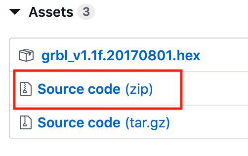
We follow word for word the instructions linked above:
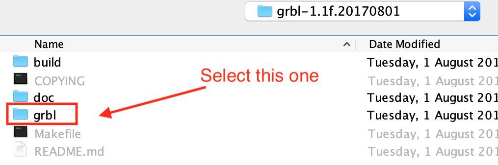
Add the GRBL library to Arduino IDE
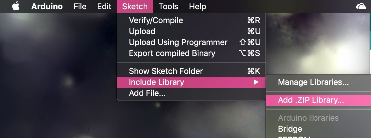
Selecting the 'grbl' folder
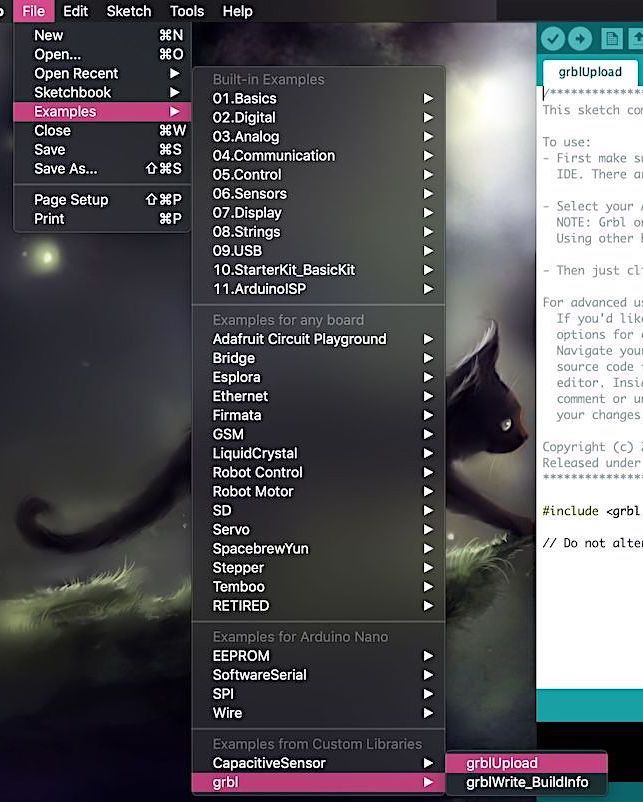
Opening the grblUpload example
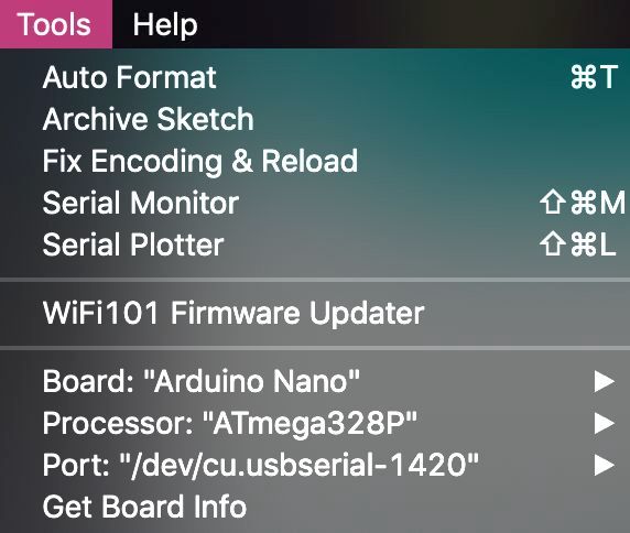
Selecting the right board settings
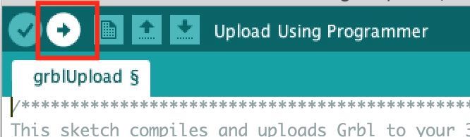
Select upload to flash the board on the CNC
End result message
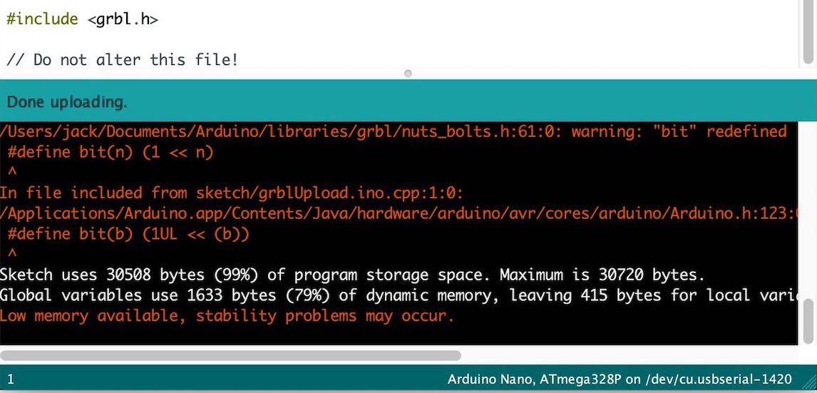
And we’re done. Cool.
Now, the question is control, having it plug directly to my PC has many inconveniences, such as:
- Taking up a USB port
- Taking up CPU resources
- MacOS not having great support for CNC control software
- Having a CNC run right next to my work-space
Remote Control Using Raspberry Pi
So, I’m going to set up a Raspberry Pi (which I had laying around) to control the CNC remotely.
I will utilize it’s VNC capabilities to control it from my desktop.
Basically, given you have a working Raspberry Pi (with Raspbian) just follow this guide:
The VNC viewer app I use is -> Real VNC
Once everything is setup and you know the IP of your Pi (using ifconfig on the terminal app on your Pi)
you can connect to your Pi by opening the RealVNC app and writing the aforementioned IP.
 Insert your Raspberry’s IP here
After which following screen, asking for your credentials:
 Enter your credentials (make sure you changed them from default for security reasons)
Now we can connect to the Pi remotely.
bCNC
To control the CNC we need a special control software like the one for Shopbots.
There are many options out there but I opted for bCNC for it’s universality and auto-levelling functions.
For some reason the instruction on Installation (using pip = recommended!)
gives me some Failed building wheel for Pillow error and doesn’t work.
So, we’re going to have to go manual here, again, by following -> Installation (Linux package maintainers)
First, we open the directory in which you want save bCNC & we run:
git clone https://github.com/vlachoudis/bCNC.git
Once that’s done we can run:
cd bCNC
# mkdir -p /usr/lib/python2.7/site-packages/ # Needed in case the site-packages folder doesn't exist
cp ./bcnc /usr/lib/python2.7/site-packages/
You can then open bCNC by running
cd /usr/lib/python2.7/site-packages/
python2 -m bCNC
After which, your bCNC instance should start running:
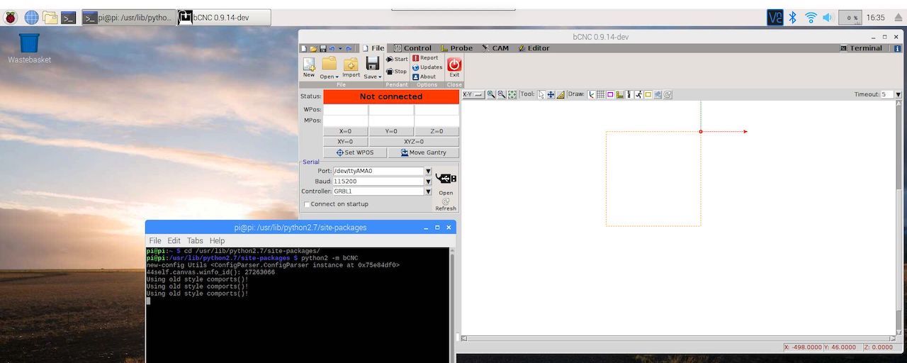
 Hot
Hot
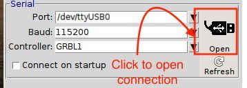
In bCNC, under the serial tab in the file page, we can select the Port, Baud & Controller, as seen below.
After which we can click open and establish a connection
If everything worked fine, the status bar will have changed from not connected to idle
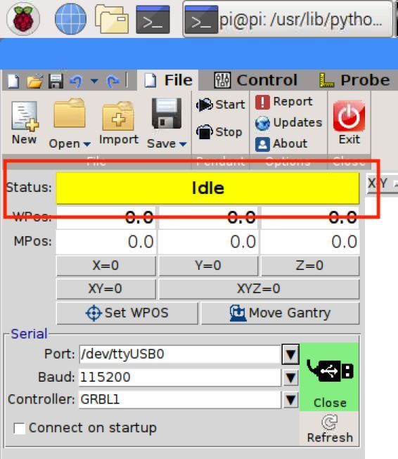
Time To Test
Discovering Design Rules for PCB Production - The Good & The Bad
Let’s take a step back, if we want anything to be milled out by this machine we need .gcode, and so far, we got none.
There are many programs that produce .gcode of all sorts.
For our use case, aka PCBs, the preferred tool seems to be FlatCam.
It’s free and well documented, the catch here is that it has a learning curve, particularly to those of us coming from fabmodules.
Secondly, FlatCam works off gerber files, fab modules uses .png,
the latter may be very limited in some sense, but I can throw any black & white image at it.
The prior, not so much.
So, fabmodules seem to be the way forward, particularly the new fabmodules which are flexible and versatile.
There is only one issue, there is no cheap chinese 3018 CNC option in
modules -> server modules, additionally I use a different milling bit!
Let’s figure this out.
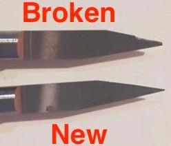
The V Bit
As the name suggest, this milling bit is shaped as a V. This means we can have different milling widths at different milling depths. If we calibrate the machine well, we are able to have smaller traces then normally possible at the given speed (bad calibration results inconsistent cut-depth, which is undesirable).
V-bits a characterized by a minimum width (mine is 0.1 mm, linked in title) and an angle, which is the slant at which it tapers (mine is 20°), the smaller the angle, the smaller the increase per depth-cut (higher precision, lower sturdiness).
With some testing, we can get a (almost) guaranteed path width relative to the cut-depth.
In our case, a depth of 0.1 mm is what we need to cut threw the copper, now we need to figure out what resolution a 20° v-bit permits, keeping in mind the best we can do is 0.1mm (width-wise).
It would be best to have two passes of 0.05 mm each, but halving the cut-depth won’t allow you to double the feed-rate (it will go at most 1.5x faster), meaning it will be at least 25% overall slower, but this can be more gentle on the fairly brittle milling bit.
I personally opted against this (except for my first try ever), but it’s personal preference, since you might be able to get longer tool life and better results.
Obviously I will be using this only for milling the traces, I will use a standard 1/32 for the cutouts.
Spring Loaded V-Bit
It would be cool to have a spring loaded v-bit.
This can’t be achieved with the ER11 collet I use, but with some fantasy it could be done on the Modela (or this machine if I changed chuck).
If you did, you could have UV solder masks and remove them with the CNC, pretty neat.
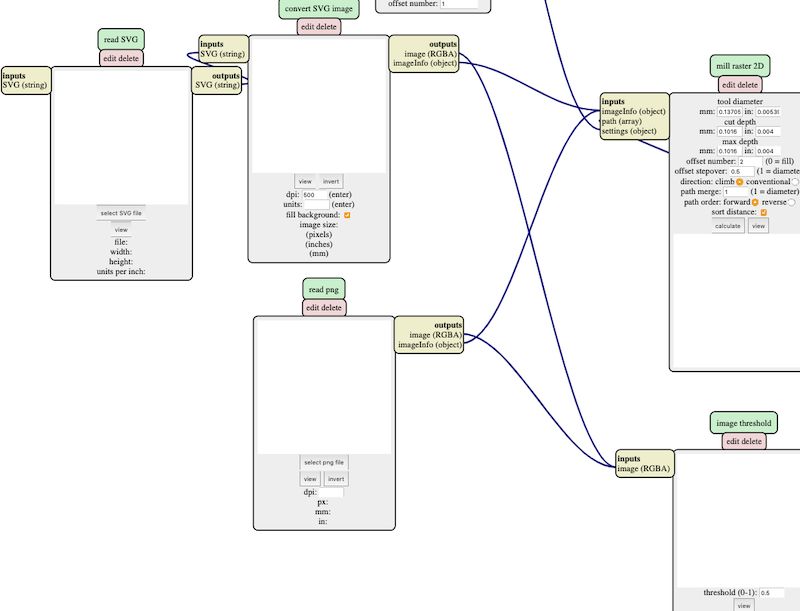
The Fab Modules for .gcode
Fab modules don’t include anything for my particular CNC, but I can assemble my own program to generate the .gcode I need, in particular I only have to take the Roland Modela program for milling PCBs and strip the communication, add a.gcode , and file save node.
You can download the changed modules on their own, or the entire program in the download section at the bottom of this page.
SVG & PNG
For convenience, I also added both SVG & PNG processing in a single program, which I can rewire depending on the use.
The fab modules use png as input to their image processing nodes, so the SVG compatibility basically only added an intermediate node that converts SVG to PNG.
Therefore, overall, I only needed to add these two extra nodes (SVG input + conversion node) and the program was able to handle SVG.
PCB Defaults
I’ve added several new PCB defaults, to include the range of mills I use throughout the weeks.
This of course includes the V-bit, but also others like the 1 mm end mill.
The name of the buttons for the set PCB defaults must contain (in) otherwise the settings aren’t sent, don’t know why, but thanks to that I’ll need to convert mm to inches for consistency.
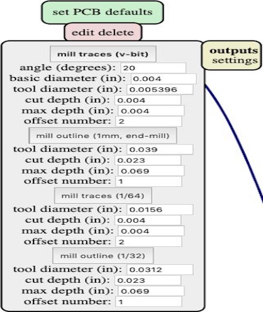
Yes, I cheated, I rounded the 0.1mm conversion from 0.00393701 to 0.0039. Looks prettier.
Plus don’t forget 0.1 is only the minimum width, since the V bit has increasing diameter.
¯\_(ツ)_/¯
On that note, we actually should include an automatic way to determine the cut width given a certain cut depth. The mathematics for this a fairly straightforward, just simple trigonometry, a quick google search will expose online tools to do this calculation, of which this is my favorite.
The reason for that being, it presents the formula for doing the calculation.
We can add just a short snippet of code in the nodes input section that will perform that calculation and will give us the actual cut width.
// initialization
var init = function() {
   add_output('mill traces (v-bit)')
   add_variable('angle (degrees)','var04')
   mod.var04.value = '20'
   add_variable('basic diameter (in)','var05')
   mod.var05.value = '0.004'
   add_variable('tool diameter (in)','var06')
   add_variable('cut depth (in)','var07')
   mod.var07.value = '0.004'
   add_variable('max depth (in)','var08')
   mod.var08.value = '0.004'
   add_variable('offset number','var09')
   mod.var09.value = '2'
   holder = parseFloat(mod.var05.value) + ((parseFloat(mod.var04.value) * parseFloat(mod.var07.value)) / 57.29)
   holder = holder.toFixed(6)
   mod.var06.value = '0.005396'
   //
One thing to note here is that, because those are input values, if we open the sourcecode of the node, the values will be overwritten by what’s in the input box.
To avoid overwriting the equation I separated it on a different line, and every time I need to perform a new calculation I need to enter the code and copy-paste the holder variable into the right place.
This is a bit fiddly, and I’m sure there is a better way to do this, but I couldn’t afford to search for one, suggestions are welcome.
Save File
One thing I noticed is that the output of the save module is .nc,
the not sure why or what that is, but looking at the contents it’s effectively .gcode.
We will replace this extension with .gcode, additionally we will remove the extension from the original file name so that we don’t get as output eg. linetest.png.gcode which I detest.
The first change to make is in view toolpath, we need to remove the extension from the name of the file, we can do that in the input block, as follows:
// inputs
var inputs = {
   toolpath:{type:'object',
      event:function(evt){
         mod.path = evt.detail.path
         // -- CHANGE HERE --
         mod.name = evt.detail.name.split('.').slice(0, -1).join('.') // removes .png/.svg
         // was -> mod.name = evt.detail.name
         mod.dpi = evt.detail.dpi
         mod.width = evt.detail.width
         mod.height = evt.detail.height
         mod.depth = evt.detail.depth
         show_path_info()
         show_path()
         outputs.toolpath.event()
         }}}
path to G-code, we need to remove the .nc extension :
// outputs
var outputs = {
   file:{type:'',
      event:function(str){
         obj = {}
         // CHANGE  HERE --
         obj.name = mod.name+".gcode"
         // was -> obj.name = mod.name+".nc"
         obj.contents = str
         mods.output(mod,'file',obj)
         }}}
//
You could probably make both fixes in path to G-code, but this way it will display the correct name.
List of Changes
After several weeks of bending the fab modules to my will, they have been modified pretty heavily, so I can’t screen-shot and list every change I’ve made, as such I only listed the major ones. All the changes are of course included in the download files for the curious.
Back To Milling
Once we have done that we can go back to do the milling.
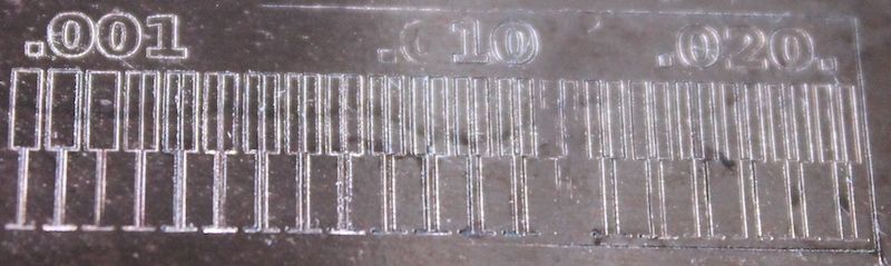
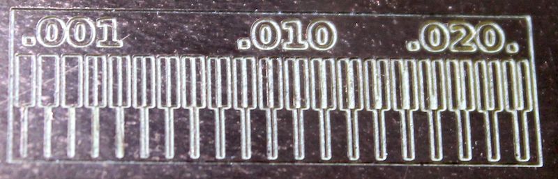
In our instance, we will do run the line benchmarking .png test.

Having done this, we will know the tolerances for this machine, which we will need for future PCB designs.
Knowing that surface unevenness is the source of many (if not most) failed CNC jobs, I took to heart auto-levelling features, which bCNC makes painless.
Particularly, the surface probing and auto-levelling features are a god-send.
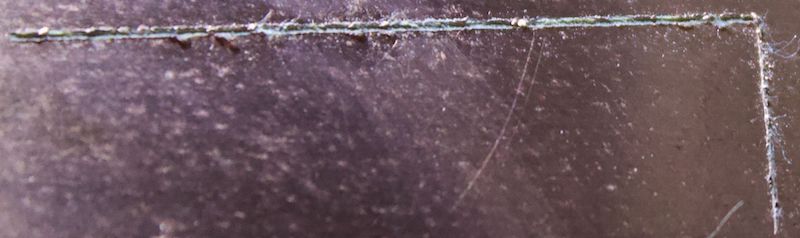
The 1st Was a Fail
I was hoping the homing feature would raise the head when making a move, turns out it DOES NOT.
It dragged the mill across a good4cm.
This is what happened to my end mill and copper board sigh
The 2nd Was Half a Fail
Before starting the job I had not set the zero height properly and adjusted the zero for the auto-levelling results, meaning the cuts were shallow and didn’t not cut threw the copper!
The 3rd Was a Success - Proper Setup Guide
Preparation Steps
Before we can turn on the machine, we need to set up the working area.
This requires few, fairly simple, steps:
1 -> Mount sacrificial layer (or ensure solidly fixed) by clamping it down to the bed
2 -> Apply double-sided tape to back of copper-clad board & fix onto the sacrificial layer
3 -> Clamp down negative probe with the bed (for auto-levelling and probing) to avoid detachment while moving.
4 -> Tape negative probe to copper-clad board
5 -> Load the milling bit (this is achieved by loosening the ER11 collet)
bCNC - Etiquette Guide
In it’s current state, this CNC machine has no safety procedures, no limit switches, no emergency switch off (that isn’t unplugging the machine).
For this reason, when operating this machine, you’re not only posing an economical risk, but a health risk as well (almost like a tiny version of the shop bot).
Care must be taken when operating this machine.
Whenever I turn on the machine, I follow a mantra like set of steps (this assumes you already loaded the material)
1 -> Zero all the axis at the current point
When you first turn on the machine, it will have random values set as the home/zero point (whatever it fetches from RAM), zeroing it out is a must,
considering we do not have limit switch to perform a true homing operation.
2 -> Set the movement distance to something small, usually1 mm
The last thing I want is accidentally pressing an arrow key when the travel distance is set to 100 mm and have 15x such operations execute because of the arrow key.
(2.5-> Open the .gcode file)
3 -> Home the x/y axis roughly at the right spot, but at least 30 mm higher then the bed, open the .gcode file, and run the scan operation.
This will:
-
Indicate the rough working area, and whether the current material is sufficient.
-
Move debris to the edge of the rails, which can be wiped off
-
Check that nothing gets knocked against by the milling bit (clamps, cables, etc.)
Plunge Depth
The next most important step is to ensure is that the mill can plunge to the desired depth, this has been a persistent fatal mistake I’ve made while milling.
The CNC 3018 has a plunge depth of 4cm, meaning the z-axis can travel at most 4cm, this is obviously greatly in excess of the depth needed to cut out a copper board (1.75 mm).
However, this poses an interesting problem, if at the point of maximum extension, the milling bit can’t reach the material, or can’t plunge deep enough into the material, then our cut will fail.
The length of the milling bit itself is 3.227 cm, roughly half of which is the blade, to ensure proper grip ~1cm of the shank should reside within the ER11.
There are several ways to fix this:
- Raise the bed to be closer to the ER11 (the best solution, but requires taller sacrificial layer eg. taller material)
- Lowering the motor (Risky, as you want maximum grip over the motor to disperse vibration but efficient)
- Lowering the milling bit (Risky, basically decrease the grip length between the ER11, and the shank)
In practice, I needed a combination of all three to fix this problem fully, I doubled my sacrificial layer by having two boards of MDF instead of 1,
lowered the motor around 5 mm and tended to be more generous with the shank grip length (can’t give precise numbers, since I eyed this setting).
Last two options are risky, they both increase axial procession, which results in a less precise milling path and added risk of braking the milling bit.
The best solution would be to have a thick sacrificial layer, something like 1 cm acrylic with and 3 mm of MDF on top of that.
Homing The Machine Properly
The next step is to home the machine at the correct point, for this we will be using the probe operation.
1 -> Test that the probe works
For the probe operation we will need to have working piezo feedback; we can test it by touching the positive crocodile clip on the copper board, in the interface next to idle a [P] will appear when contact is made.
2 -> We can attach the positive crocodile clip to the milling bit
3 -> Move the milling bit to the point we want using the controls, remain ~2mm above surface, and zero xyz.
4 -> Run a scan operation again and make sure you’re happy with where the cnc will mill (make sure to use the largest file!)
5 -> Run a home operation, set the probe feed & probe pos
The default value for the probe feed is 10.00 (also called pluge rate), this is good for precision, but a higher value (30~40) will actually counteract play in the bed by stopping fractional amount later and pushing down the bed. Probe pos should be -2 or -3 depending how far your milling bit is from the bed.
6 -> Ensure everything is connect and run a probing operation
The milling bit will lower, touch the board and (hopefully) stop. This is our home/origin and we can zero xyz at this point.
Auto-levelling With bCNC
The auto-levelling procedure has a delicate workflow, which is as follows (assuming you homed properly)
1 -> Open the file with the largest margins (most likely cutout)
2 -> Select margins operation, which will set the auto-levelling grid to be within the margins of the file
One thing to note in the case of the margins operation is that, because we are getting the dimensions of the probing area,
and we won’t be able to probe once we etch the traces, it’s smarter to actually load the cutout .gcode and use those margins,
rather than the first file that you will be milling.
3 -> Choose the number of horizontal and vertical lines in the grid (aka probling points)
The general rule with the bCNC auto-levelling procedures, the more points you use, the better.
There is a certain amount of error to account for during the auto-levelling procedure, especially since the auto-levelling is single probe.
The auto-levelling height between un-probed points is determined using linear-interpolation. This means that, if a given point is imprecise, and the distance between this point and it’s 8 neighbours is large, every path between that point, and it’s neighbours will be wrong.
This, of course, should be taken with some sanity, running a (50x50, 2500 points) probe grid would be excessive for a 3x3 cm board.
A general guideline would be to have a (5x5~8x8) probe grid for about 1 cm^2^ of board.
4 -> Select probe feed (15~25mm is good), and probing distance (from 0.75 to -0.75) and start the auto-levelling procedure.
The basis of how I learned to do this was this video:
-> How to mill a PCB - The Ant Way
Starting The Job
Once auto-levelling is done, we can move the gantry to the center of the cutout with move gantry, perform one last probing operation, zero auto-levelling results at that point & we’re ready to start.
Remove the positive crocodile clip from the milling bit, make sure the right .gcode file is selected and select start.
The machine will now begin. (I usually apply a small amount of water with dishwasher soap onto the surface to limit the amount of dust propagated in the air).
This is how the final result looks:
Some other great guides on milling PCB’s
-> How to mill a SMD PCB with a CNC
-> Make Your Own PCBs on an Inexpensive Desktop CNC Mill
-> Milling PCBs with cheap Chinese “desktop” CNC-router
Conclusion
I really think this CNC puts the £5,799 Roland Modela to shame in terms of price-to-quality.
Although, it’s fair to say, I was never able to replicate such great results again!
Download The Files
-> Compressed Folder Containing Costume V-Bit Milling Fab Module Program (HTML & TXT file)