WEEK 16:
MECHANICAL DESIGN, MACHINE DESIGN
GROUP ASSIGNMENT: -make a machine
-including the end effector
-build the passive parts and operate it manually
-document the group project and your individual contribution
STUDENTS
Antonio BurraiMassimiliano Dibitonto
Elena Papetti
Michela Ruggiero
Marco Sanalitro
Leonardo Zaccone
DOWNLOAD
'Model'
'Prototype'
'Electronics'
'Code'
'Interface'
WHAT WE MADE
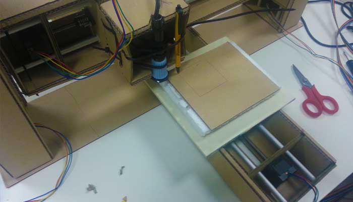
For this week assignment we decided to made a 4-axes Polystyrene Cutting Machine.
We wanted to build a machine reproducing the sample 'Machine that makes'.
We wanted to build a machine reproducing the sample 'Machine that makes'.
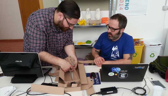
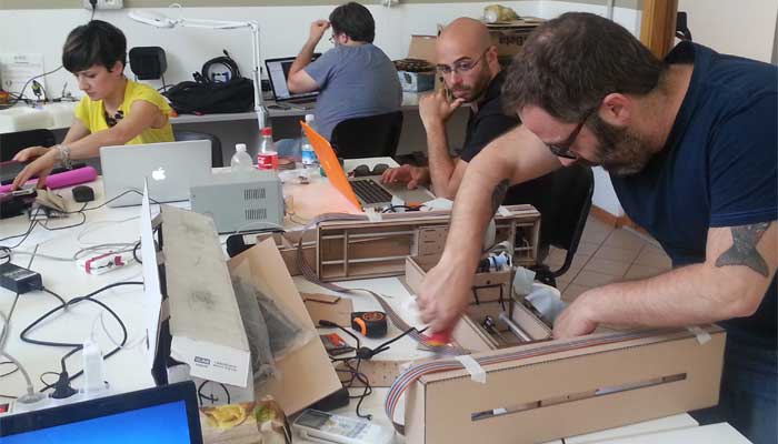
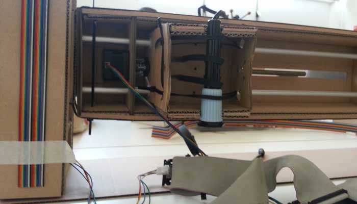
-MODELING,PROTOTYPING AND CONSTRUCTION.
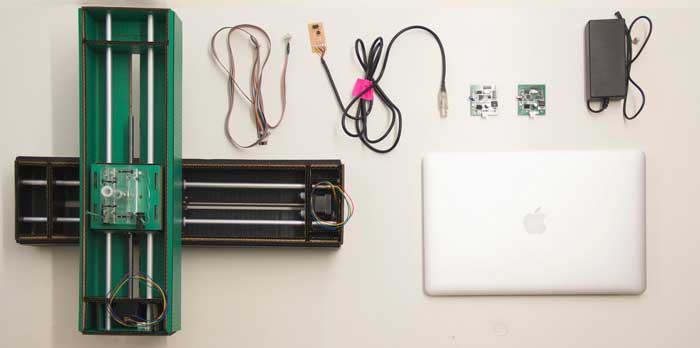
Our kit includes:
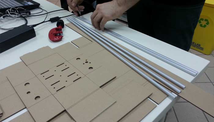
-4 stages = stepper + rod bar
-8 guide bars
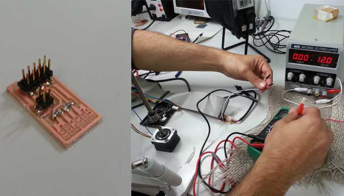
-4 gestalt circuit boards
-misc materials as nylon bearings
-RS485 connecting cable
-4 resistor
-plugs
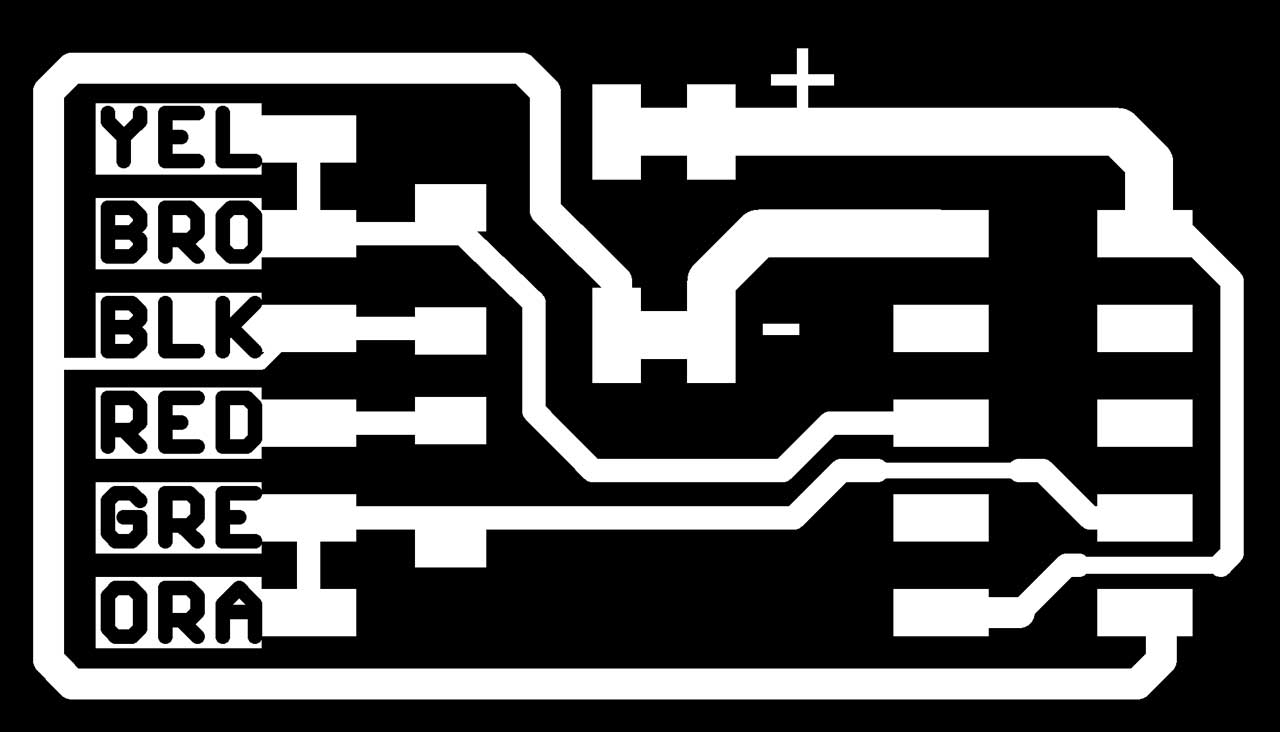
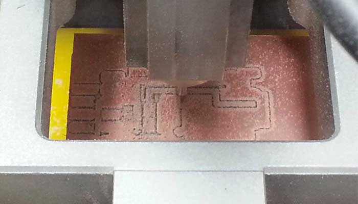
Checked all the material we started milling and soldering the FabNet.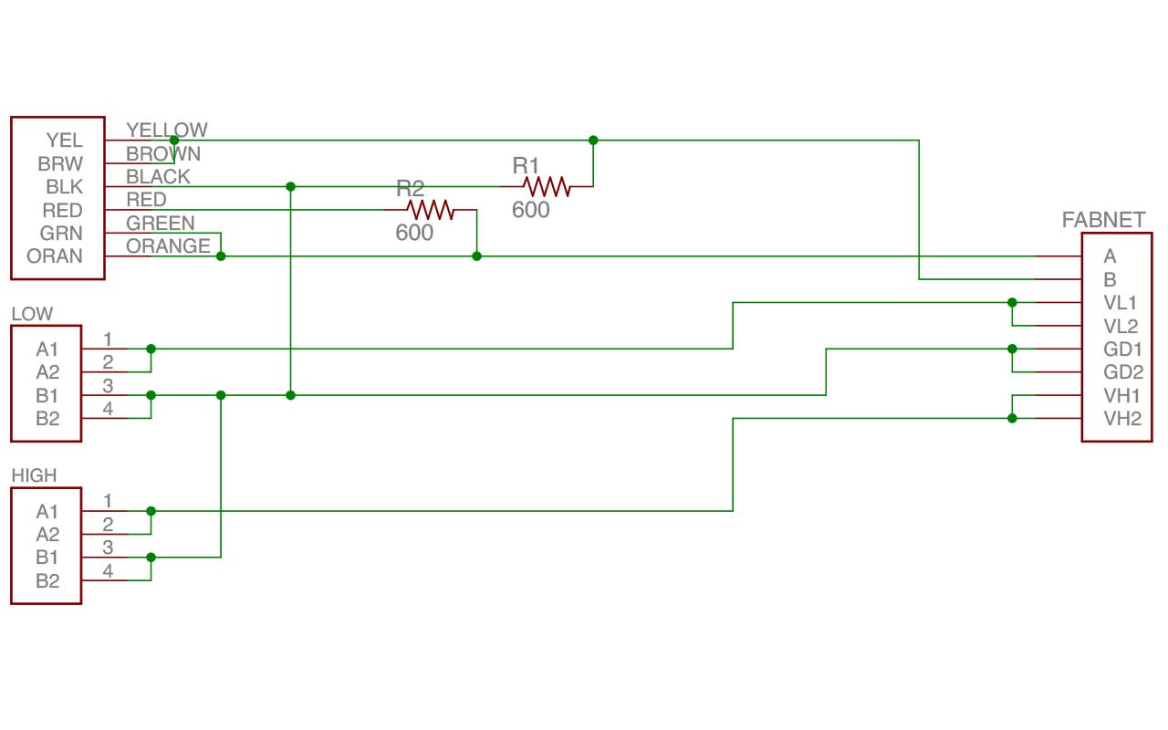
 We decided to draw a model with a 'HOT END' tool.
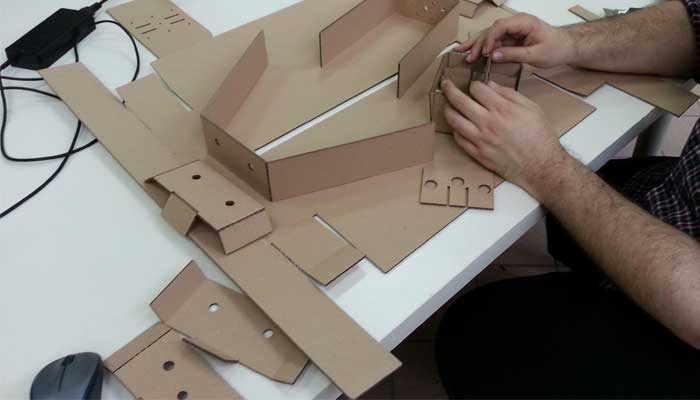
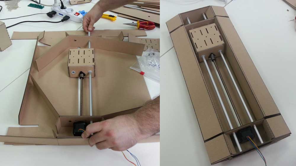
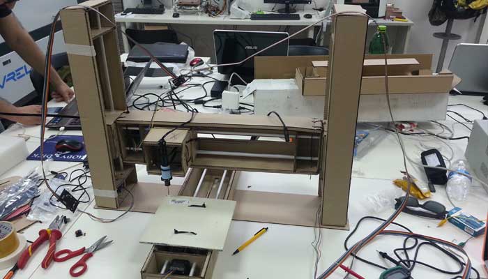
For the modeling we opted for a structure based on a gantry crane.
The scheme have been chosen in order to realize a very stable structure.
Our Machine is defined on the following DOFs(Deegrees of Freedom):
-Z1 is coincident with Z2, z-DOF
-the cutting tool is fixed at the x-DOF
-the object to be cut is fixed at the y-DOF
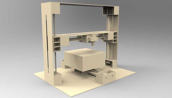
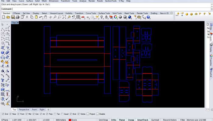
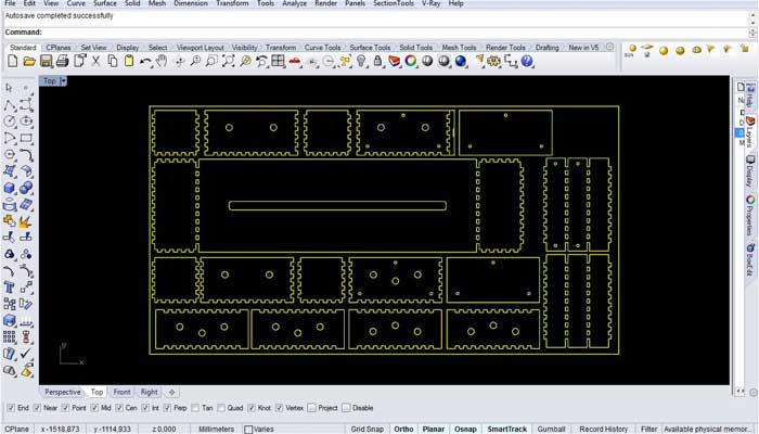
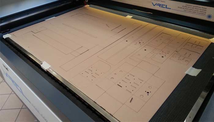
The 3d complete model has been designed, including all the information required to cut the part using the laser cutter.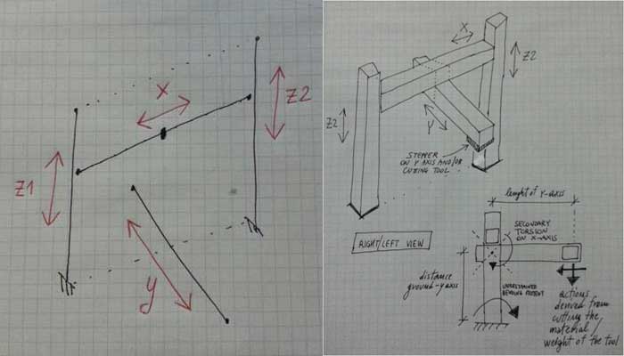
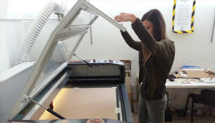
 After we lasered the stage using the DXF settled and exported from the cutfiles available in the fab inventory.
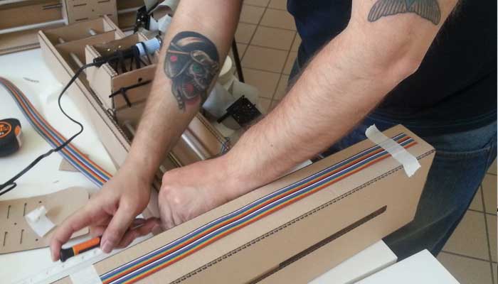
We decided to made the Machine using the Panels of Cardboard we have in the Fab Lab. The size of it are (800 x 1200 x 2.5)mm.
After we lasered the stage using the DXF settled and exported from the cutfiles available in the fab inventory.
We decided to made the Machine using the Panels of Cardboard we have in the Fab Lab. The size of it are (800 x 1200 x 2.5)mm.
-4 stages = stepper + rod bar
-8 guide bars
-4 gestalt circuit boards
-misc materials as nylon bearings
-RS485 connecting cable
-4 resistor
-plugs
Checked all the material we started milling and soldering the FabNet.
We decided to draw a model with a 'HOT END' tool.For the modeling we opted for a structure based on a gantry crane.
The scheme have been chosen in order to realize a very stable structure.
Our Machine is defined on the following DOFs(Deegrees of Freedom):
-Z1 is coincident with Z2, z-DOF
-the cutting tool is fixed at the x-DOF
-the object to be cut is fixed at the y-DOF
The 3d complete model has been designed, including all the information required to cut the part using the laser cutter.
After we lasered the stage using the DXF settled and exported from the cutfiles available in the fab inventory.
We decided to made the Machine using the Panels of Cardboard we have in the Fab Lab. The size of it are (800 x 1200 x 2.5)mm.
-PROGRAMMING, INTERFACING AND CODING.
PROGRAMMING:
The architecture of the Gestalt system is very interesting. Each node is networked and is represented inside a virtual machine. In this way is very easy to configure a new machine. We didn’t find an extensive documentation of methods and properties of the gestalt library so we did a bit of reverse engineering using the examples and the comments in the code.
A very useful file is functions.py that is well commented and helps understanding the main methods of the library.
Moreover we studied also the remote procedure call routines using also the page 'http://tq.mit.edu.'
To make the machine work you need to install:
-The gestalt library
-Python setup.py install
-Pyserial (if not installed because Pygestalt need pyserial for serial communication with the nodes.)
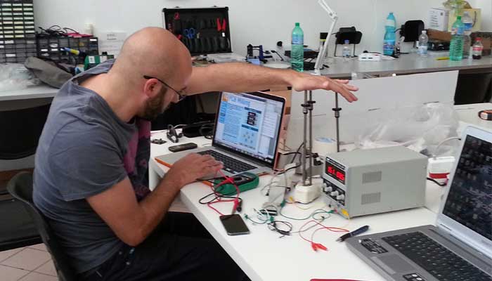
It is important to do not hot plug the boards. So the correct procedure is connecting the boards together and to the Fabnet, connect them to the pc and then to the power supply.
To connect the boards together you can use a ribbon cable. Pay attention to the two connectors on the board. One for in and one for out. Always check the polarity when plugging the cable.
From a software point of view, if you want to create new machine, you have to import the Gestalt library.
-From pygestalt import:
1) Nodes
2) Interfaces
3) Machines
4) Functions
-From pygestalt.machines import:
1) Elements
2) Kinematics
3) State
-From pygestalt.utilities import: notice
-From pygestalt.publish import: rpc #remote procedure call dispatcher
-Import time
-Import io
Next you define the virtual machine class that is a set of functions and parameters that defines the machine (i.e. number of axis, kinematics etc), class virtualMachine(machines.virtualMachine).
Then you tell to gestalt how to connect with the nodes.
Here is important to change the name of the serial port used:
-def initInterfaces(self): if self.providedInterface: self.fabnet = self.providedInterface #providedInterface is defined in the virtualMachine class.
else: self.fabnet = interfaces.gestaltInterface('FABNET', interfaces.serialInterface(baudRate = 115200, interfaceType = 'ftdi', portName = '/dev/tty.usbserial-FTXW9L60'))
A very important part is the definition of the axis. Here you can define how many axis will have your machine. In the definition there is also the python file that describes the virtual node class, with important parameters and routines of the nodes. We have 4 nodes of the same type but you can have different type of nodes together.
The last line defines the compound nodes. It is useful as you can treat the nodes as one. Sending a command to a compound node affects all the nodes that are listed in it.
In our case we have two axis (z and k) that make the same moves def initControllers(self):
-self.xAxisNode = nodes.networkedGestaltNode('X Axis', self.fabnet, filename = '086-005a.py', persistence = self.persistence)
-self.yAxisNode = nodes.networkedGestaltNode('Y Axis', self.fabnet, filename = '086-005a.py', persistence = self.persistence)
-self.zAxisNode = nodes.networkedGestaltNode('Z Axis', self.fabnet, filename = '086-005a.py', persistence = self.persistence)
-self.kAxisNode = nodes.networkedGestaltNode('Z Axis', self.fabnet, filename = '086-005a.py', persistence = self.persistence)
-self.xyzkNode = nodes.compoundNode(self.xAxisNode, self.yAxisNode, self.zAxisNode,self.zAxisNode,self.kAxisNode)
-self.zkNode = nodes.compoundNode(self.xAxisNode, selfkAxisNode)
Another important point is where you can set the kinematics properties of the nodes.
They depends on the physical characteristics of the nodes used (step, microstep, pulleys etc).
It is very important to correctly set up the parameters or it will result in an incorrect movement of the node especially regarding the correspondence between the machine coordinates and real world coordinates.
def initKinematics(self):
-self.xAxis = elements.elementChain.forward([elements.microstep.forward(4), elements.stepper.forward(0.9), elements.pulley.forward(11.6), elements.invert.forward(True)])
-self.yAxis = elements.elementChain.forward([elements.microstep.forward(4), elements.stepper.forward(0.9), elements.pulley.forward(11.6), elements.invert.forward(True)])
-self.zAxis = elements.elementChain.forward([elements.microstep.forward(4), elements.stepper.forward(0.9), elements.pulley.forward(11.6), elements.invert.forward(True)])
-self.kAxis = elements.elementChain.forward([elements.microstep.forward(4), elements.stepper.forward(0.9), elements.pulley.forward(11.6), elements.invert.forward(True)])
-self.stageKinematics = kinematics.direct(4) #direct drive on all four axes
Then you can initialize the functions for moving the machine. You can see the corresponding class in the functions.py file. Here we initialize the map and the job command. As we have a compound node (z and k) we set it as the third argument that will be sent to the machine.
When you create an instance of the machine with this line
instancename = virtualMachine(persistenceFile = “filename.vmp")
you create a “persistence file” that stores the machine configuration.
Indeed when you first run your code the nodes will start flashing and a message will ask you to identify the axis.
You have to press a button on the the gestalt board to tell to the system the correct axis sequence. If you want to reconfigure that you just have to delete the .vmp file.
Then you can choose the way you want to control the machine. You can include the virtual machine into a python program, you can put the commands directly into the code or you can use the RPC to remotely call the functions of the gestalt.
We used the last one.
You can expose functions with this command:
-rpcDispatch.addFunctions(('move',desktopFactory.move),
('position', virtualmachine.getPosition),
('jog', virtualmachine.jog),
('disableMotors', virtualmachine.xyzkNode.disableMotorsRequest),
('loadRemote', fileReader.loadFromURL),
('loadLocal', fileReader.loadFromFile),
('runFile', fileReader.runFile),
('setPosition', virtualmachine.setPosition))
As we didn’t find a complete documentation to better understand how to call the remote procedures we analyzed the calls made by the following site:
'http://tq.mit.edu.'.
We created a command to load a local files or a remote file containing a path that the machine will follow.
Inside the file we put commands that are mapped into another RPC function:
fileReader.addFunctions(('move',virtualmachine.move), ('jog', virtualmachine.jog))
Indeed reading from a file is better than send commands from a website as HTTP protocol is stateless and there is a risk of a delay due to network issues.
Here you can see the code to make a simple square:
/move?position=[None,None,-2,-2]&velocity=1
/move?position=[None,80,None,None]&velocity=1
/move?position=[80,None,None,None]&velocity=1
/move?position=[None,0,None,None]&velocity=1
/move?position=[0,None,None,None]&velocity=1
/move?position=[None,None,10,10]&velocity=1
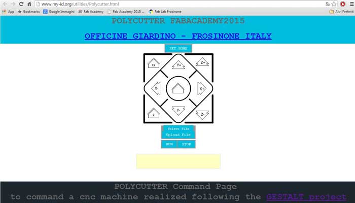
WEB INTERFACE:
We made a first interface prototype visible at
'http://www.my-id.org/utilities/test_interface_5.html'
that sends commands to the machine using ajax calls.
We planned the following workflow:
- jog the machine to reach an home position
- set the home position (set position 0 on every axis)
- load a file
- run the file
After we made a second interface always using html5.
You can target the function you need by a browser, addressing to 'http://127.0.0.1:27272/'
The commands we use are:
/setPosition?position=[0,0,0] set the actual position as zero.
/move?position=[x,y,z]&velocity=v the 3 values are the coordinates that each axis reaches. “none” doesn’t move it. “v” is the speed machine value.
/jog?incrementalPosition=[x,y,z] the 3 values are the numbers of step that each axis jogs. no velocity needed. negative numbers to reverse direction.
/disableMotors to stop the machine immediately and disable the motors.
/runfile? to run the uploaded file.
CODING:
To use the machine more easily, we wanted to develop a system that allowed us to mill 2D and 3D shapes using curves and surfaces drawn with any CAD.
To do this we used the plug-in for Rhino, Grasshopper, implementing it using Python scripts.
Importing the initial files into Rhino, selecting the curve or surface, assigning the size of the tool and the precision of the step, it will automatically generate a list of the coordinates of the route of the cut.
1. Sometimes the machine stops to react to the commands even if the software continues to send (the debug messages say {'writePosition': 0, 'stepsRemaining': 255, 'readPosition': 1, 'currentKey': 0, 'statusCode': 0}).
However the two led in the usb plug start blinking very fast. Probably is some buffer overflow in the serial communication. Supporting this theory is the fact if the codes restarts sometimes the machine executes the last command sent.
2. The last node of the physical chain sometimes doesn’t react to the commands.
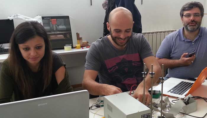
Moreover I see that using several axis together draws a lot of current (up to 3 Amps) and the boards can become really hot.
The architecture of the Gestalt system is very interesting. Each node is networked and is represented inside a virtual machine. In this way is very easy to configure a new machine. We didn’t find an extensive documentation of methods and properties of the gestalt library so we did a bit of reverse engineering using the examples and the comments in the code.
A very useful file is functions.py that is well commented and helps understanding the main methods of the library.
Moreover we studied also the remote procedure call routines using also the page 'http://tq.mit.edu.'
To make the machine work you need to install:
-The gestalt library
-Python setup.py install
-Pyserial (if not installed because Pygestalt need pyserial for serial communication with the nodes.)
It is important to do not hot plug the boards. So the correct procedure is connecting the boards together and to the Fabnet, connect them to the pc and then to the power supply.
To connect the boards together you can use a ribbon cable. Pay attention to the two connectors on the board. One for in and one for out. Always check the polarity when plugging the cable.
Testing Steppers and Coordinates:
From a software point of view, if you want to create new machine, you have to import the Gestalt library.
-From pygestalt import:
1) Nodes
2) Interfaces
3) Machines
4) Functions
-From pygestalt.machines import:
1) Elements
2) Kinematics
3) State
-From pygestalt.utilities import: notice
-From pygestalt.publish import: rpc #remote procedure call dispatcher
-Import time
-Import io
Next you define the virtual machine class that is a set of functions and parameters that defines the machine (i.e. number of axis, kinematics etc), class virtualMachine(machines.virtualMachine).
Then you tell to gestalt how to connect with the nodes.
Here is important to change the name of the serial port used:
-def initInterfaces(self): if self.providedInterface: self.fabnet = self.providedInterface #providedInterface is defined in the virtualMachine class.
else: self.fabnet = interfaces.gestaltInterface('FABNET', interfaces.serialInterface(baudRate = 115200, interfaceType = 'ftdi', portName = '/dev/tty.usbserial-FTXW9L60'))
A very important part is the definition of the axis. Here you can define how many axis will have your machine. In the definition there is also the python file that describes the virtual node class, with important parameters and routines of the nodes. We have 4 nodes of the same type but you can have different type of nodes together.
The last line defines the compound nodes. It is useful as you can treat the nodes as one. Sending a command to a compound node affects all the nodes that are listed in it.
In our case we have two axis (z and k) that make the same moves def initControllers(self):
-self.xAxisNode = nodes.networkedGestaltNode('X Axis', self.fabnet, filename = '086-005a.py', persistence = self.persistence)
-self.yAxisNode = nodes.networkedGestaltNode('Y Axis', self.fabnet, filename = '086-005a.py', persistence = self.persistence)
-self.zAxisNode = nodes.networkedGestaltNode('Z Axis', self.fabnet, filename = '086-005a.py', persistence = self.persistence)
-self.kAxisNode = nodes.networkedGestaltNode('Z Axis', self.fabnet, filename = '086-005a.py', persistence = self.persistence)
-self.xyzkNode = nodes.compoundNode(self.xAxisNode, self.yAxisNode, self.zAxisNode,self.zAxisNode,self.kAxisNode)
-self.zkNode = nodes.compoundNode(self.xAxisNode, selfkAxisNode)
Another important point is where you can set the kinematics properties of the nodes.
They depends on the physical characteristics of the nodes used (step, microstep, pulleys etc).
It is very important to correctly set up the parameters or it will result in an incorrect movement of the node especially regarding the correspondence between the machine coordinates and real world coordinates.
def initKinematics(self):
-self.xAxis = elements.elementChain.forward([elements.microstep.forward(4), elements.stepper.forward(0.9), elements.pulley.forward(11.6), elements.invert.forward(True)])
-self.yAxis = elements.elementChain.forward([elements.microstep.forward(4), elements.stepper.forward(0.9), elements.pulley.forward(11.6), elements.invert.forward(True)])
-self.zAxis = elements.elementChain.forward([elements.microstep.forward(4), elements.stepper.forward(0.9), elements.pulley.forward(11.6), elements.invert.forward(True)])
-self.kAxis = elements.elementChain.forward([elements.microstep.forward(4), elements.stepper.forward(0.9), elements.pulley.forward(11.6), elements.invert.forward(True)])
-self.stageKinematics = kinematics.direct(4) #direct drive on all four axes
Then you can initialize the functions for moving the machine. You can see the corresponding class in the functions.py file. Here we initialize the map and the job command. As we have a compound node (z and k) we set it as the third argument that will be sent to the machine.
When you create an instance of the machine with this line
instancename = virtualMachine(persistenceFile = “filename.vmp")
you create a “persistence file” that stores the machine configuration.
Indeed when you first run your code the nodes will start flashing and a message will ask you to identify the axis.
You have to press a button on the the gestalt board to tell to the system the correct axis sequence. If you want to reconfigure that you just have to delete the .vmp file.
Then you can choose the way you want to control the machine. You can include the virtual machine into a python program, you can put the commands directly into the code or you can use the RPC to remotely call the functions of the gestalt.
We used the last one.
You can expose functions with this command:
-rpcDispatch.addFunctions(('move',desktopFactory.move),
('position', virtualmachine.getPosition),
('jog', virtualmachine.jog),
('disableMotors', virtualmachine.xyzkNode.disableMotorsRequest),
('loadRemote', fileReader.loadFromURL),
('loadLocal', fileReader.loadFromFile),
('runFile', fileReader.runFile),
('setPosition', virtualmachine.setPosition))
As we didn’t find a complete documentation to better understand how to call the remote procedures we analyzed the calls made by the following site:
'http://tq.mit.edu.'.
We created a command to load a local files or a remote file containing a path that the machine will follow.
Inside the file we put commands that are mapped into another RPC function:
fileReader.addFunctions(('move',virtualmachine.move), ('jog', virtualmachine.jog))
Indeed reading from a file is better than send commands from a website as HTTP protocol is stateless and there is a risk of a delay due to network issues.
Here you can see the code to make a simple square:
/move?position=[None,None,-2,-2]&velocity=1
/move?position=[None,80,None,None]&velocity=1
/move?position=[80,None,None,None]&velocity=1
/move?position=[None,0,None,None]&velocity=1
/move?position=[0,None,None,None]&velocity=1
/move?position=[None,None,10,10]&velocity=1
WEB INTERFACE:
We made a first interface prototype visible at
'http://www.my-id.org/utilities/test_interface_5.html'
that sends commands to the machine using ajax calls.
We planned the following workflow:
- jog the machine to reach an home position
- set the home position (set position 0 on every axis)
- load a file
- run the file
After we made a second interface always using html5.
You can target the function you need by a browser, addressing to 'http://127.0.0.1:27272/'
The commands we use are:
/setPosition?position=[0,0,0] set the actual position as zero.
/move?position=[x,y,z]&velocity=v the 3 values are the coordinates that each axis reaches. “none” doesn’t move it. “v” is the speed machine value.
/jog?incrementalPosition=[x,y,z] the 3 values are the numbers of step that each axis jogs. no velocity needed. negative numbers to reverse direction.
/disableMotors to stop the machine immediately and disable the motors.
/runfile? to run the uploaded file.
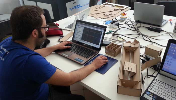
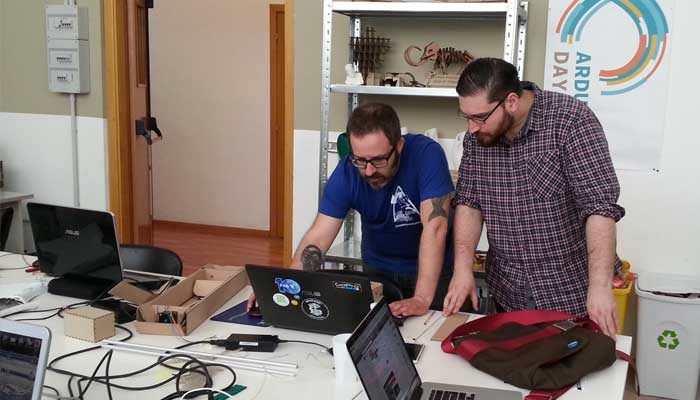
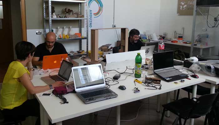
Testing Interface and Machine:
CODING:
2D & 3D Coordinates Definition:
To use the machine more easily, we wanted to develop a system that allowed us to mill 2D and 3D shapes using curves and surfaces drawn with any CAD.
To do this we used the plug-in for Rhino, Grasshopper, implementing it using Python scripts.
Importing the initial files into Rhino, selecting the curve or surface, assigning the size of the tool and the precision of the step, it will automatically generate a list of the coordinates of the route of the cut.
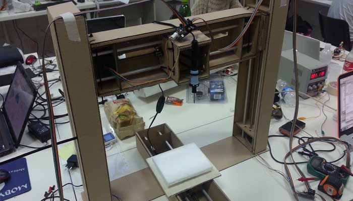
-FUNCTIONING OF OUR MACHINE
Using the machine we encountered some problems that we weren’t able to solve.1. Sometimes the machine stops to react to the commands even if the software continues to send (the debug messages say {'writePosition': 0, 'stepsRemaining': 255, 'readPosition': 1, 'currentKey': 0, 'statusCode': 0}).
However the two led in the usb plug start blinking very fast. Probably is some buffer overflow in the serial communication. Supporting this theory is the fact if the codes restarts sometimes the machine executes the last command sent.
2. The last node of the physical chain sometimes doesn’t react to the commands.
Moreover I see that using several axis together draws a lot of current (up to 3 Amps) and the boards can become really hot.
Cutting Polystyrene and Drawing a Square: the Machine works!