Performer - Sound Artist - UX Designer

He was co-founder of our FabLab and now he's the event manager. He is a very close friend to me, while asleep!
He was born in Rome where he played Lego and Music. He used to live in Berlin, but finally he came back!
He was the main promoter of my company's success, I can't imagine it without his support, I really love him!
He's a great artist, an astonishing sound performer and instruments maker, his music of silence enchants me...

In the Week#1 I realized this personal website using HTML5. I focused on the sections I really need, and then I decided to create not more than 4, WEEKLY PROJECTS, FINAL PROJECT, ABOUT ME and CONTACT ME.
The Weekly Project section is a list of icons I would replace with more meaningful images. I didn't create an html page for each project, but I'm using the Responsive Modal Window system, an architecture that includes in each icon of the WP list an internal #hyperlink. Clicking on the icon, it opens a window showing the assigned project.
Following my artistic and daily idea of playing the life, I wrote a very ironic About Me section. The Contact Me section is just a link that opens the email client inserting my email address on the to line.
Then I learned how to use github and upload my weekly assignments.
FINAL PROJECT DESCRIPTION
I would realize an interactive music instrument. I called it MODULAR RAINBOWPHONE because the project has been started form the PurplePhone, an earlier synth I realized using Arduino and a light sensor.
This project is modular because I would realize a control box in which you can insert each input shield you can build following an open standard I give, and every input shield could be realized using a different sensor.
For my work, I mind to realize a photoresistor light sensor, a color detector and a interactive textile sensor.
I could use a Raspberry PI 2.0 to handle the interaction and generate sounds using the software pure data, so the instrument could work without a laptop, or I could realize a command box to be connected, by serial or midi,to a common sound generator, as a laptop or a digital sound instrument.
To create nice visual effect during the sound performance, I will place an infinity mirror with a RGB ledstrips back the loudspeaker, in order to change colors and blinking delay of ledstrips following the music parameters.
Anyway I need to realize:
the DAC and loudspeaker board
the wireless control box
some sensor shield
the wireless command box
the wireless RGB driver shield
an infinity mirror
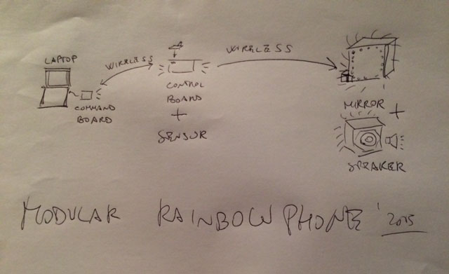
At the end, the instrument will be composed in three parts:
command box connected to a sound generator
portable control box
infinity mirror - loudspeaker

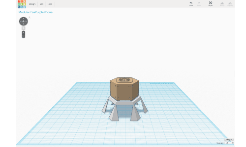
In the Week#2 I designed the 3d model of my instrument. I started using the software I already knew, THINKERCAD, realizing the esagonal model with a command console on top and the speaker on bottom and the holes fort the sensors on each side, and the table in which the instrument could be inserted.
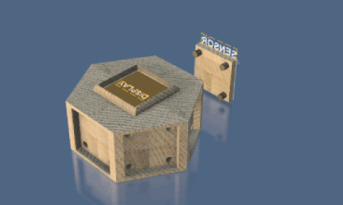
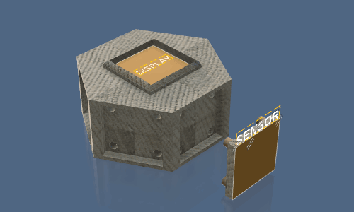
 Then I started to use a more professional software, AUTODESK FUSION 360, and I copied the early model adding a best resolution of the holes and a version of a modular sensor plane. Instead I didn't designed the table, because I wasn't satisfied of it and for sure I want think it better.
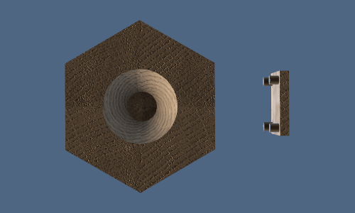
That's the first time in my life I rendered and it was a nice experience! I decided to export 3 render images, 2 top lateral views, showing better the sensor plane and the attach sistem, and a bottom view, showing better the cone for the speaker.
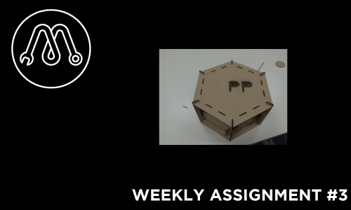
During this third week assignment, I started to learn a nice software I never used before as Rhinoceros. At the same time, I cut with a lasercutter for the first time in my life.
DESIGN with RHINOCEROS
I decided to draw a press fit model of my final project, as it means an hexagonal box with 6 hollowed side faces and a loudspeaker at bottom.
File Sources and some images on thingiverse
At first I designed the box without loudspeaker. To render the sticking out corners, I planned to fit every face up and down beneath two rectangle 2 cm far from the hexagons edge, and to connect each couple of sides using as joint 6 rectangular corner tile fixed at hexagons corner.
 Then I decided to realize the loudspeaker model too, using 6 concentric circles, 7 counting the circle in the middle of the base, each of them 1 cm above and 2 cm of diameter bigger than the next one.
With the aim to fasten more as possible the box, I chose to insert the 6 friction point to fit the 6 circles at the 6 corner tile, adding to them a diagonal section.
That was a good solution to me, even if it creates some fitting problems, because each corner tile has to be joined to other 10 pieces (2 sides, top, bottom and 6 circles).
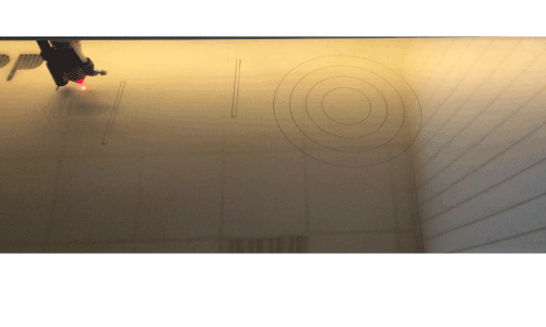 CUTTING with LASERCUTTER
As I told, I have never cut with laser before, so it was very exciting. The first step was exporting the .dxf file.
I had a cardboard sheet 1.2 x 0.7 m so I placed all the pieces of the design to save space, checking if I have enough, as it was.
In the model I planned to cut 3 of the 6 circles directly from the bottom hexagon.
I learned how to save a file to lasercut it, selecting “R12 Lines & Arcs” option.
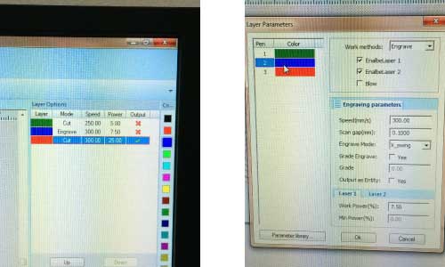
 Using the machine was relatively easy, I mean more than a 3d printer. I imported the .dxf on the proper software and then I assigned to each form the respective color. Actually all pieces to be cut but the letters on the top hexagon. I added those letters just to experience engrave and etching, so I assigned to E the etching color and to PP the engrave.
Me and my mates spend an afternoon optimizing the values of speed and power to the cardboard 2.5 mm and we found out:
cut 200 25 11
engrave 300 7.5
etching 250 5.8 5
Anyway, it didn’t work as well as expected. Engrave and etching was perfect but the cut of pieces was not deeper as needed, so I had to cut a second time turning off engrave and etching.
 FITTING the PIECES
To find out if the joint beneath 2 bases, 2 sides and a corner fit works good, I rendered it in 3d in Rhinoceros.
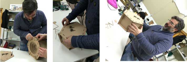
It was a good suggest by my tutor, but the software join the surfaces just in virtual way, I had to join them physically and it was very hard! A good experience that thought to me a lot of things about press fit planning! 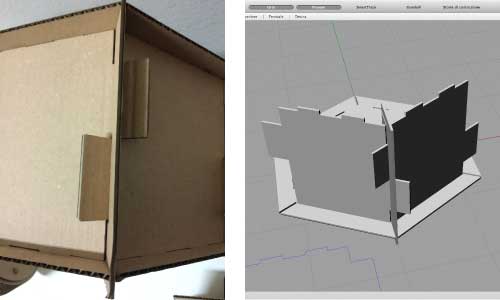 So I needed a second person helping me to press together all pieces and parts, and a lot of time thinking the best way to join everything.
At the end, I realized I did a mistake, because was impossible join the top to the corner sliding it laterally, as I planned, but I had to press it downward, fastening it by 18 friction points. So I modified the design of the corner tiles, as we can see in the next image, and I cut them again. Then everything worked. 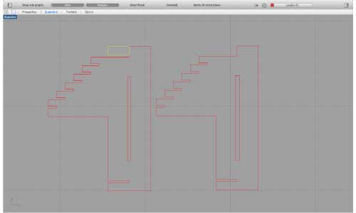
To push together all pieces, follow this order:
On the hexagon base (hole in the center) join 4 corner pieces and the 3 sides between.
Then join all circles. Now join out of base the 2 corner and 3 sides left.
Then press this group of pieces all together on the base, joining the outer sides of each group too.
At last press the top hexagon to the body fastening it with 18 friction points.
 Click on this
link
to the source files and more images on thingiverse.
3D SCANNING
During this week I explored a series of 3d-scan methods to define the difference and to improve myself.
I used in order
3dSense and his software at FabLab Giardino with my FabAcademy mates and tutor,
Kinect and skanect at my FabLab (Roma Makers)
iPhone 5 and 123D Catch at Museum Centrale MonteMartini in Rome
At Frosinone was just a first attempt to scan an object. I try to scan a fire estinguisher, putting it on a table in a corner of the room and moving myself around the object. I was not satisfied by the results. The main problem I found was the difficulty to walk around an object keeping always the same distance from it.
The day after I scanned the Robot EMILIO at FabLab Roma Makers using our Kinect. It works better, probably just because I started from my early experience. The problem here was the capture of 2 triangles in the bottom part. The angle of capture, slightly over the middle of the body, generate a blind point under those two surfaces protruding the upside down cone. So the triangles were kept as holes. I used MeshMixer to flatten the cone but the result is not so good.

The day after again I went to Centrale MonteMartini and there I used 123D Catch with my iPhone to scan some ancient roman statue here exposed between old electric machines. I chose to capture a bronze statue of Agrippina. The reason I chose to scan this statue was that it stays in a good enlightened empty wide space. So I could walk around it without obstacle, moving my body slower and firmer as possible, receiving a good light even at the back of the statue. 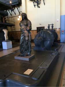
Indeed during the earlier scanning experience I got 3 important rules about a good 3d scanning:
keep the same distance from the center of the object
keep the same height of the camera view
have a good light all around the object
clearly, when we scan moving around the object is very hard to respect all those points.
The capture of Agrippina Statue really satisfied me. 123D Catch works very well. I needed to kept 33 pictures around it following the slices crown and then the cloud software gives back to me the entire room with the statue in the middle.
I clean it around using Netfabb Basic which cuts X, Y, Z very simply and quickly, without needing to repair the model. 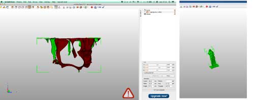
Another nice feature of 123D Catch is that you can publish your scanning projects, with .stl and all photos you kept. Download Agrippina files here.
3D PRINTING
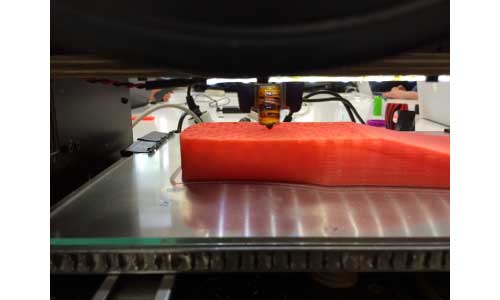 I decided to model a sandal using Rhino. I found a tutorial
realized by an architect, and I inspired my modeling to it. Respect his model, I decided to raise the heel height and I added two holes for the cloth laces I planned to insert.
 As I tried many times before, with a bow of 60 degrees or less, my PowerWasp can print this holes without problem.
The tutorial wasn’t thought for 3d printing, so I could not print the first .stl I exported. I found out how save files in Rhino to print them, closing every form in a only one polysurface. So I did and it works.
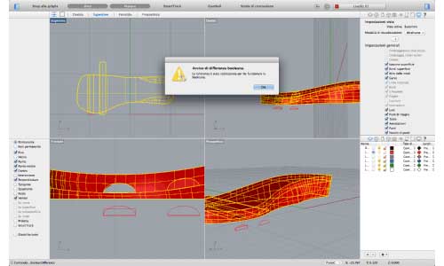 I realized the model of a right foot, and to print the left one I directly used the “mirror y” feature on Cura. The length of the model was based on the feet italian scale, number 37, it means 23.8 cm, so every sandal was printed singularly. I printed them using a PowerWasp Evo with a 0.5 nozzle. I set the layer height at 0.35 because I didn’t need a perfect resolution. I set a speed of 80 mm/s, slightly raising it manually during the bridge level of the holes. Each of two takes 2 hours and 20 minutes.
After I printed both of them I added the laces and a friend of me wore them walking for some meters. The resistance was good even if I set a normal 20% fill.
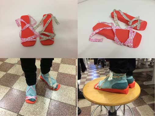 The source file are downloadable on thingiverse.
MOLDING AND CASTING
I was really excited to learn this technique I’ve seen so much about in a lot of maker faire and cosplay events.
Then I was looking for so many tutorials that I can write a short report about my work and what I found out.
This process is branched in three different phases:
PHASE A - POSITIVE PATTERN
At first we need to create the positive model we want reproduce in many copies.
We could choice among three different ways:
1 Needing the box around in which pour the silicon to create the mold, the best way is the subtractive process, using a cnc mill. In this case, we can carve the .stl model into an appropriate wax box or a chemical wood box or hard wood for metal casting.
2 With an additive process, we can 3d print it, but then we need to insert the realized model in a box. The idea to print the object and the box around is practicable but it takes more time and plastic as you really need.
3 If we physically have the object we want reproduce, we could use it directly as model just fixing it with the double-sided tape in a box.
PHASE B - THE MOLD
Once we have the positive pattern, we could realize a mold.
If the object we want reproduce has at least a face totally flat, we can realize an unique mold, putting the hole in respect of this flat face.
For complex forms, we have to create a bi-valve molding process, using two blocks, one for each half of the object. The blocks had to be fastened each to the other with some joints, so that you create a closed block with 2 small holes, one for the liquid and one for the air.
To create the mold we can use several materials: stiff ones as synthetic resins, just in case you want create rubbery objects; elastic ones as silicon, more common because make simpler extracting the casted object and are good for food grade molding too.
However, we just need to blend the fluid material with a liquid catalyst and then pour the mixture in the prepared box with the positive model. Spreading a release agent typically makes removal of the two objects easier, but using silicon you can normally avoid it.
Each material has different process times. We can define two important periods:
pot life, the maximum time in which the mixture could stay in the pot in which you blended it before pouring;
cure time, the time it need to be finished so you can extract it and use;
To conclude the process, sometimes you have to heat the mold.
If you want cast low-temperature metals as tin, you can carve a mold directly into a brass piece using a cnc mill.
PHASE C - CASTING
At the end of our process, for every time we need or want until the mold survives, we could pour a liquid in the mold and realize our object.
We could use a lot of materials as plastic, resin, metal, but even cookie dough and chocolate!
Definitely, the casting process is really similar to the pouring process used to realize the mold!
MY WORK
I completed two different casting process:
CHOCO CASTING: the first one realized following the assignment, using Roland SRM-20 mill machine to carve the positive pattern from a wax box and then using food silicon for the mold and chocolate to cast in it
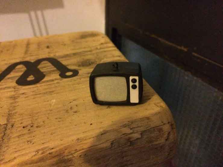 TV CASTING: the second one setting in a box a small tv I had to create the mold with the same silicon but casting in it a resin to create a plastic reproduction.
PHASE A
 To create the CHOCO positive model I used TINKERCAD. The image shows 4 different modeling phases:
At beginning I modeled the box I had using the proper sizes I measured, 167x80x37mm.
Then I emptied it creating a frame of 5x5mm and a 15 degree inclinated wall on both sides to make silicon extraction easier.
After I modeled the positive pattern, in this case two circles with my makers community logo in high and low relief, I measured the max height, 6.33mm, I added 5mm to it for the min height of the mold and I filled up the empty box until 11.33mm from the top of the box.
Finally I put the circles inside and I fused all together, saving it as .stl
Following this tutorial
I craved my positive pattern into a wax box using Modela Player 4.
 I used a 3mm square endmill for roughing
 and a 1mm square endmill for finishing
 .
.
About TV CASTING instead, I builded a box using LEGO pieces we always have in our FabLab.
 Then I just fixed it with a double-sided tape. This is a very simple and funny way to create a mold!
PHASE B
To create the mold me and my mates used this silicon Smooth-Sil 940.  As the link shows, we needed to blend the fluid silicon and the liquid catalyst 100:10 by weight. So, after calculating the volume I needed to full my patterns, I pour the silicon in a measured pot
  and the pot on a scale to check the weight.
  POT LIFE of this silicon is 30 minutes, so we had enough time, but is always better pour the catalyst in his pot directly on the scale. We used two different scales so we could check the weights directly.
 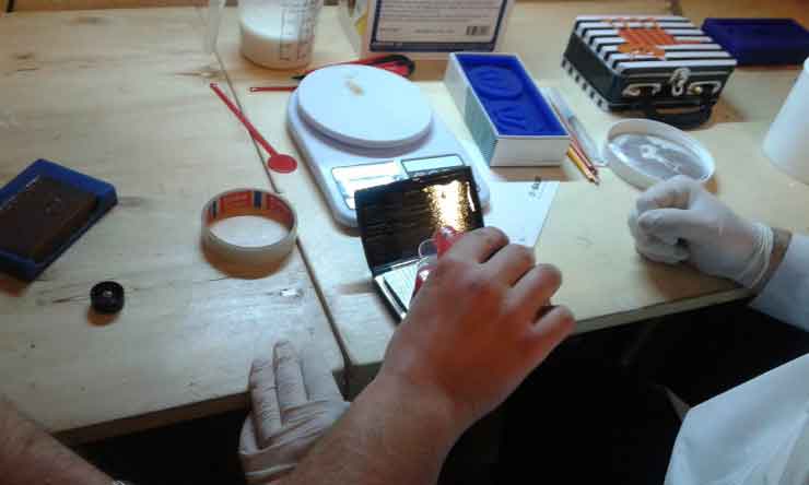 We used a small wood stick to blend the two components for ten minutes
 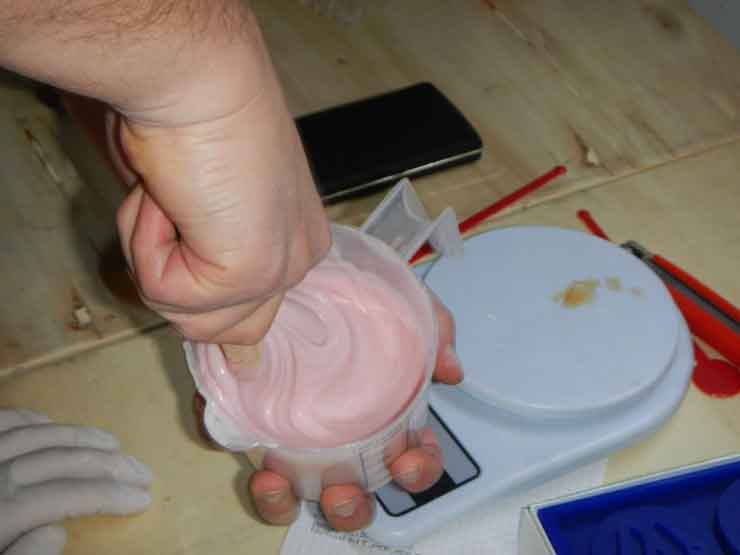 then we poured it in the wax box and in the LEGO box
 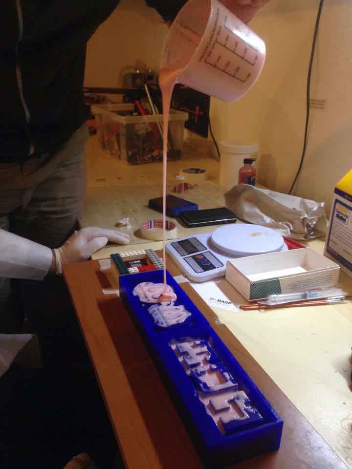 pay attention to verse a thin layer slowly, to let the fluid slide into the smaller corner of our boxes using a small brush, and then fulling everything slapping the box to help air blowing away.
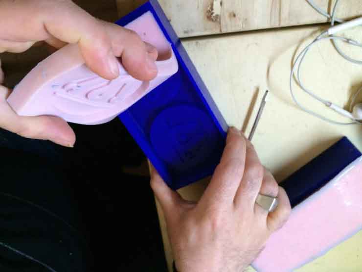
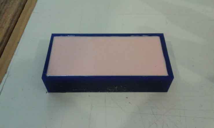 After 24 hours, cure time of this silicon, the molds were ready. I extracted it just pushing on it,
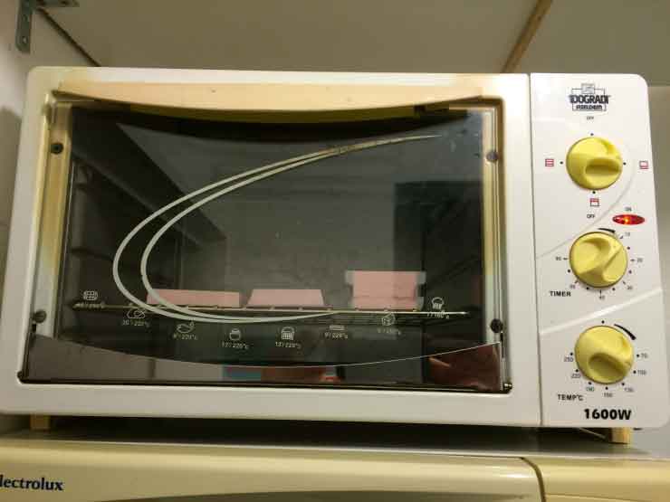
 but before the use I needed to heat for 3 hours in an electric oven, 2 hours at 80° and 1 hours at 100°.
PHASE C
I casted two different materials in the two different molds.
CHOCO CASTING was indeed more complex than using resin. I needed to melt chocolate on bain-marie for 5 minutes 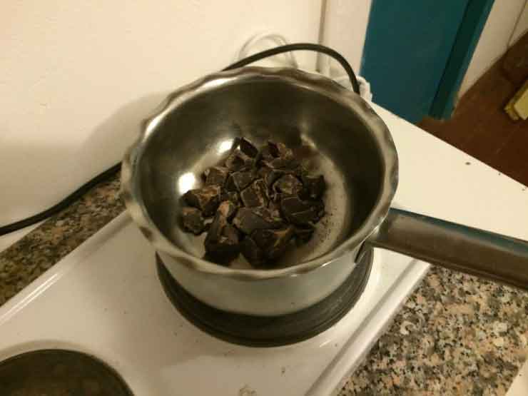 and then I poured it in the mold using a knife to flat the outside.
 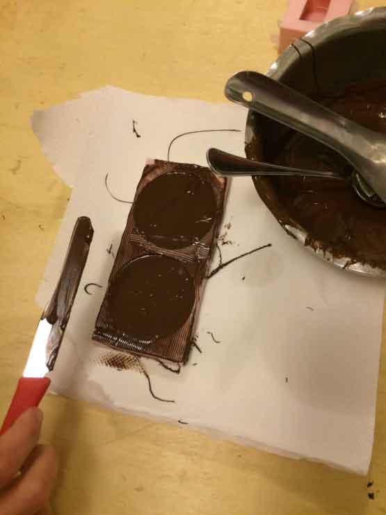 At beginning I thought that I could keep the cookies on the table but I noticed that they need at least 5 minutes in fridge to set
 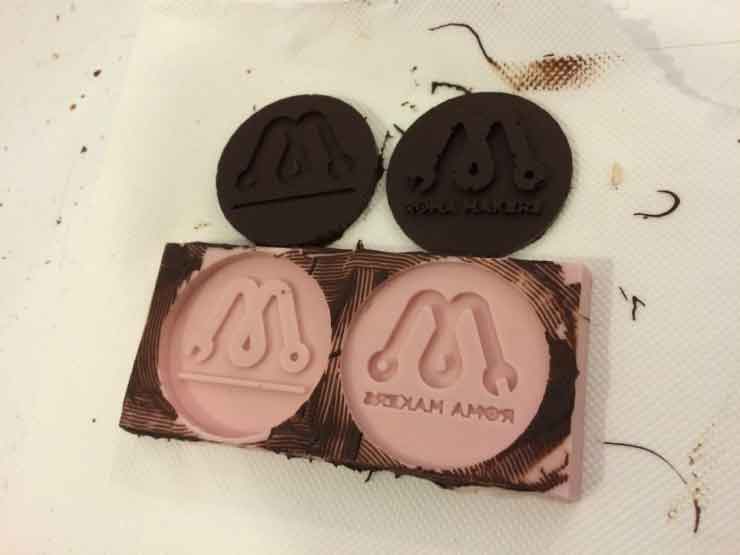 and get ready to be eaten!
 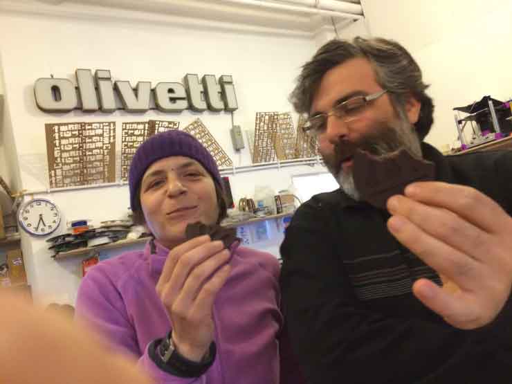 TV CASTING with resins was very interesting: I needed to blend the polyurethane with his catalyst 100:100 by volume that made it easier to prepare using the circles of a plastic glass.
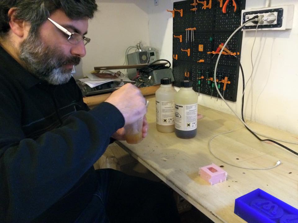
 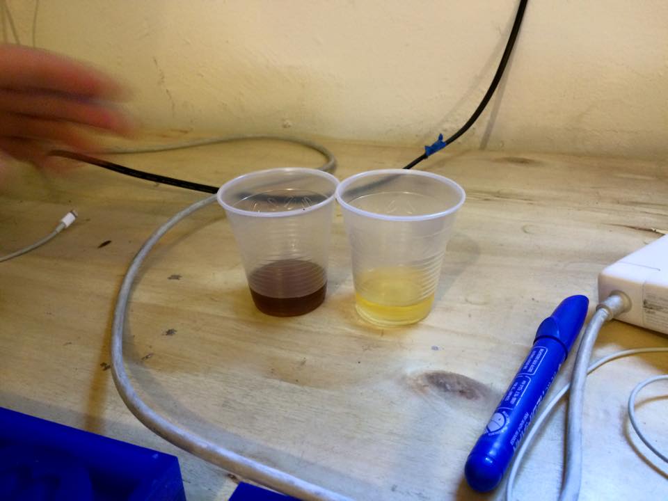 The material sheet indicates 4 minutes blending, but I noticed that after 3 minutes the catalyzation was yet active, so I tossed the first attempt and I blended a second time for only 2 minutes, until I felt the glass slightly warm.
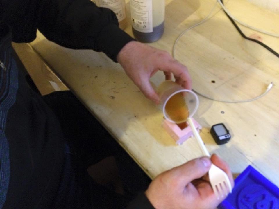
  I poured it in the mold removing with the spoon the liquid spurting out
  and after 10 minutes the TV was ready.
 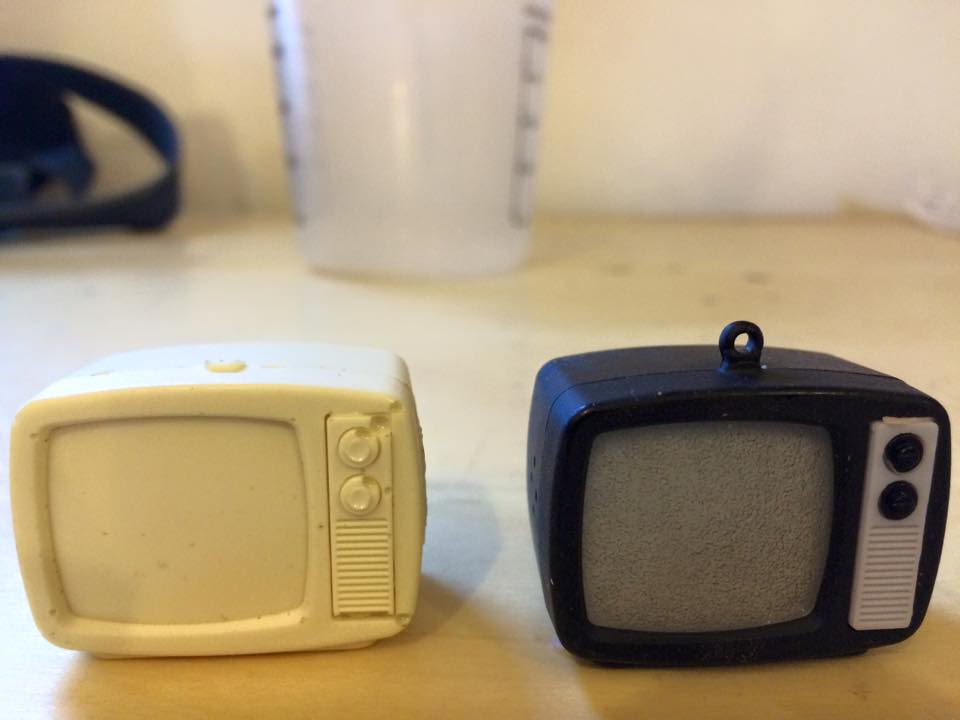 What a pity I couldn't eat it too!
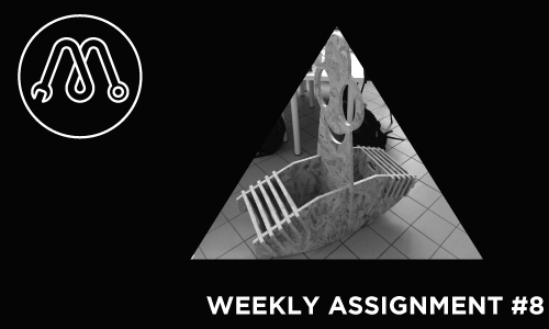
MAKE SOMETHING BIG!!!
I realized a Rolling Ghost, a standing seesaw I placed on a public children playground in front of our FabLab in Rome!
Look at the video.
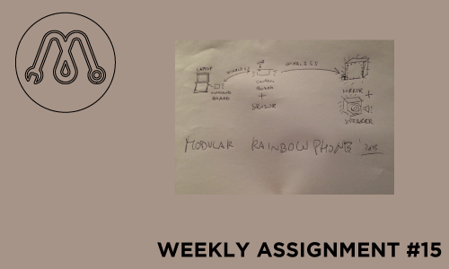
WEEK 15
APPLICATIONS AND IMPLICATIONS
what will it do?
It wil be an interactive music instrument that allows to create amazing sound and light performances, controlling both sound and light with one or more modular sensor shields
who's done what beforehand?
A lot of artists are developing in last years music instruments controlled by sensors; at the same time infinity mirrors are commonly used as light effects of a music performance;
but I’ve never find an instruments which controls both together and anyway very few instruments allows to change the input sensor in a modular and simple way as I want to.
what materials and components will be required?
three wireless box and sensor shields:
some electronic components
three PANSTAMP transceiver
2 battery 9v
1 12v transformer
copper board
plexiglass (120x90x3 cm) to realize the cover boxes
infinity mirror:
1 RGB ledstrip (1.2 m)
1 mirror (30x30 cm)
1 glass (30x30 cm)
one way mirror film
(1 meter)
wood (120x90x4 cm) to realize the frame and the body
plastic (50 cm filament) to realize the junction parts of the body
where will they come from?
electronic components
one way mirror film
copper boards, glasses, wood and plexiglas by local sellers.
PANSTAMP
Other materials (as the loudspeaker, the mirror and the LED strip) from old objects I’ve.
how much will it cost?
electronic components
TIP 31 x 3 = 0.99 €
LM1117 x 3 = 2.94 €
Polar capacitor x 6 = 9.66 €
Power Jack = 1.11 €
Screw Header = 0.55 €
Little screw x 2 = 0.70 €
Header pin = 5 €
SMD resistor x = 3 €
Photoresistor = 0.5 €
PANSTAMP transceiver 15.33 € x 3 = 45.99€
battery 9v 1€ x 2 = 2€
12v transformer 7€
copper board 4.7€ x 2 = 9.4€
plexiglass (120x90x3 cm) 30€
1 glass (30x30 cm) 12€
one way mirror film
(1 meter) 11€
wood (120x90x4 cm) 15€
plastic (50 cm filament) 3€
total = 160.3 €
what parts and systems will be made?
a DAC and loudspeaker board
a wireless control box
some sensor shield
a wireless command box
a wireless RGB driver shield
an infinity mirror
what processes will be used?
milling and soldering to realize the electronics board
lasercutting to realize the cover boxes and the wood body
3d printing to realize the junction part of the body
what tasks need to be completed?
I need to design and realize the DAC.
I need to design and realize the body of the mirror/speaker.
I need to design and realize the cover boxes of the boards.
what questions need to be answered?
I’m not sure about connecting the instrument to a laptop or to a Raspberry PI as sound generator.
I’m not sure which kind of DAC to build.
I’m developing the sound software using MAX-MSP and I’m deciding how convert the color parameters in sound parameters.
what is the schedule?
Next week (may 20/26) I will design all components I need to. I start to realize the cover boxes.
Then (may 27/ june 2) I will realize the BODY and assemble in it the mirror and the speaker.
Finally (june 3/9) I’m going to finish the sound software solving all questions physically playing the instrument.
how will it be evaluated?
A good evaluation of the instrument will be when some artist but me could play it and have fun and artistic results.
Technically, it has to be able to produces sound and light effects following same parameters, allowing to a performer to control them walking around the hall.
