Task required:
This week we assigned to design and make something big such as furniture using cnc machine.
what I did ?
- Prepare CAD for chosen object in CATIA software (I chose to make a coffee table).
- Make a sample prototype using laser cutting.
- Test cnc machine clearance by making different tolerances.
- Finally, make the real object and assemble it.
Procedure:
CAD Design
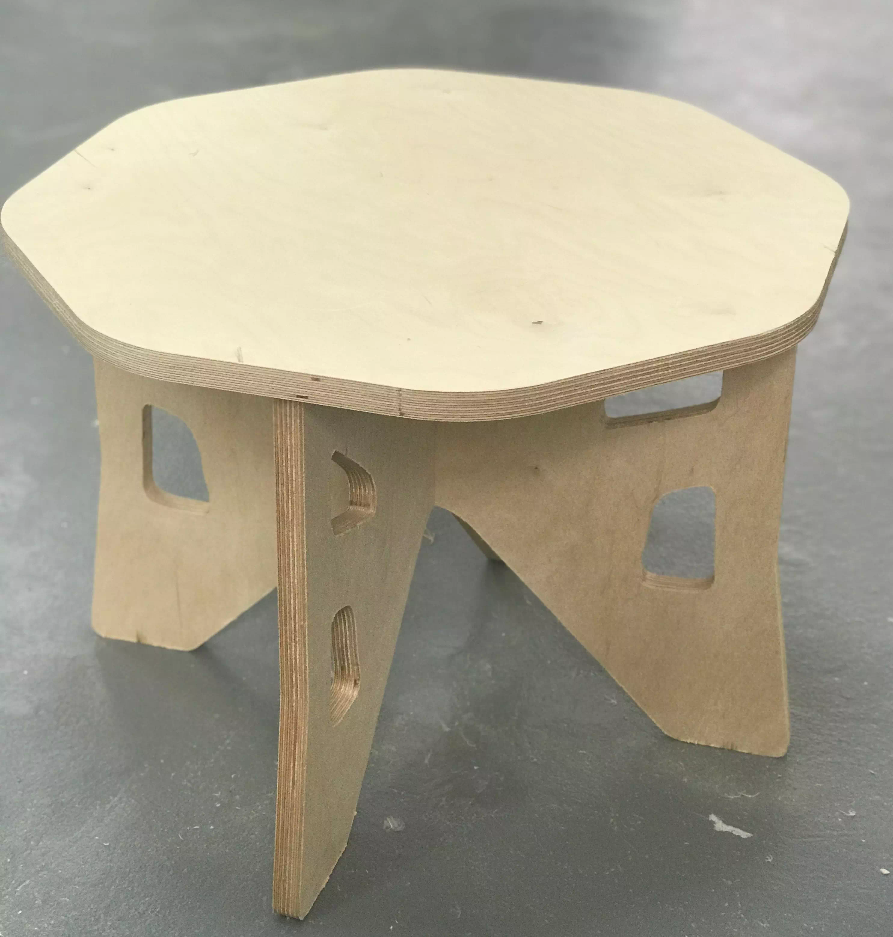
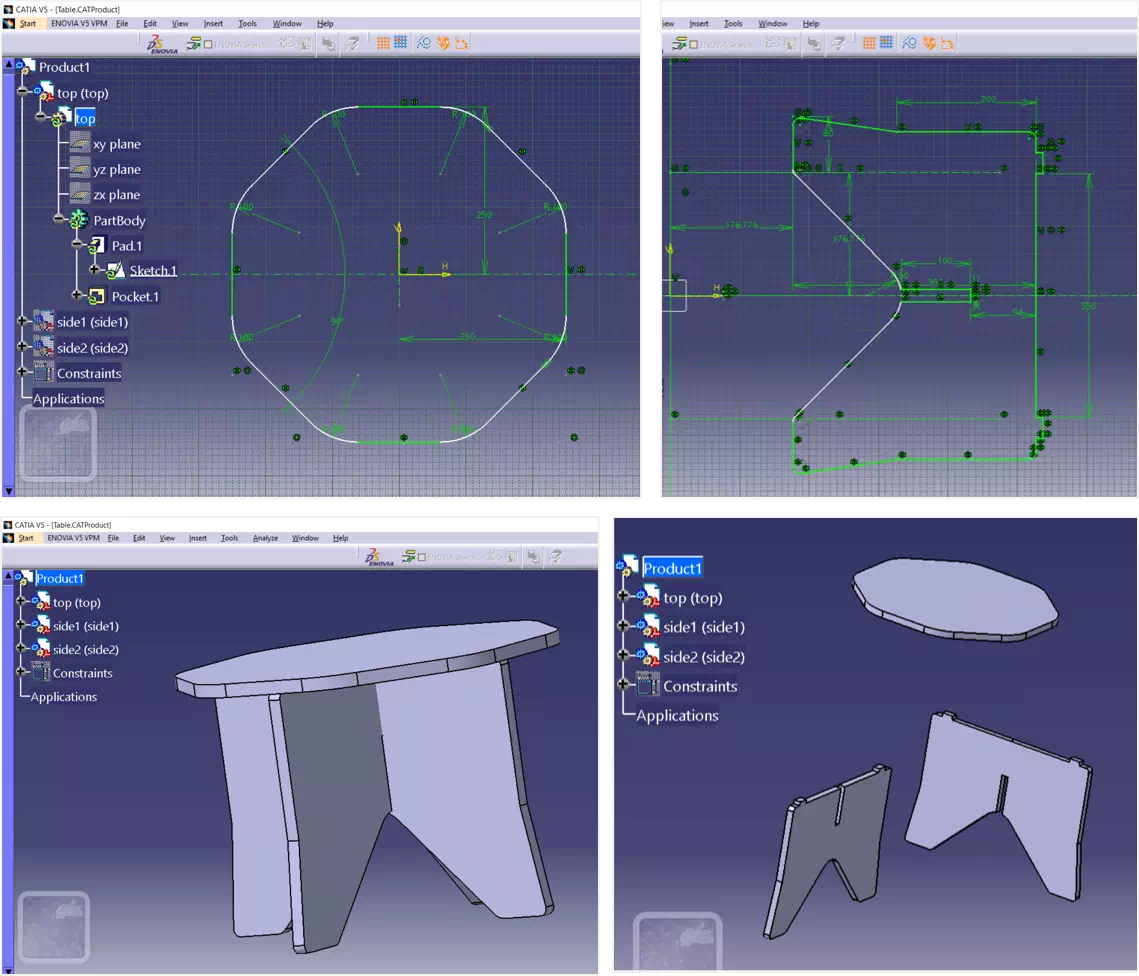
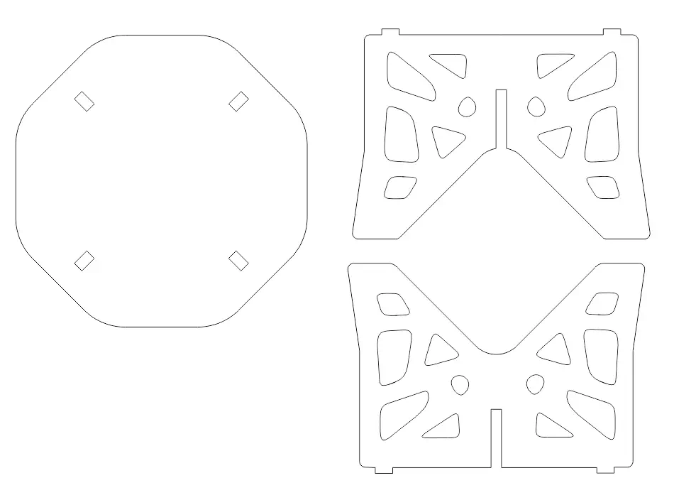
For this assignment I decided to make a coffee table. Actually, I enjoy drinking coffee. Therefore, I designed the table using CATIA which is my favorite software. The design contains three parts top, side1 and 2. The sketch done by drawing one side and use mirror option to complete the drawing. Next, pad of 18 mm was chosen as thickness for the parts. The following figures show the overall drawing design:
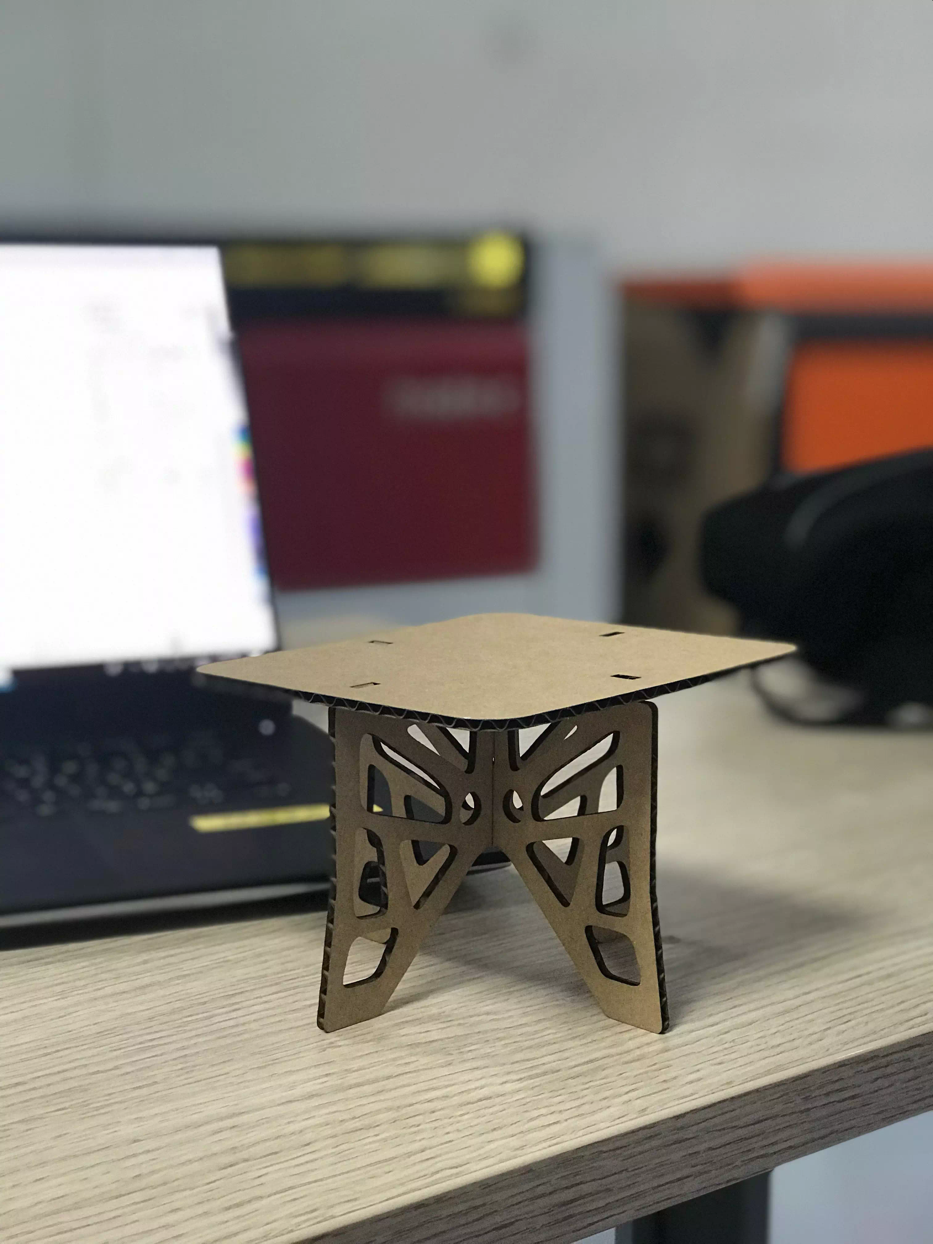
Laser cut prototype
Next, to double check the sizes and fitting I make a model shown in the figure below. It was fitting successfully.
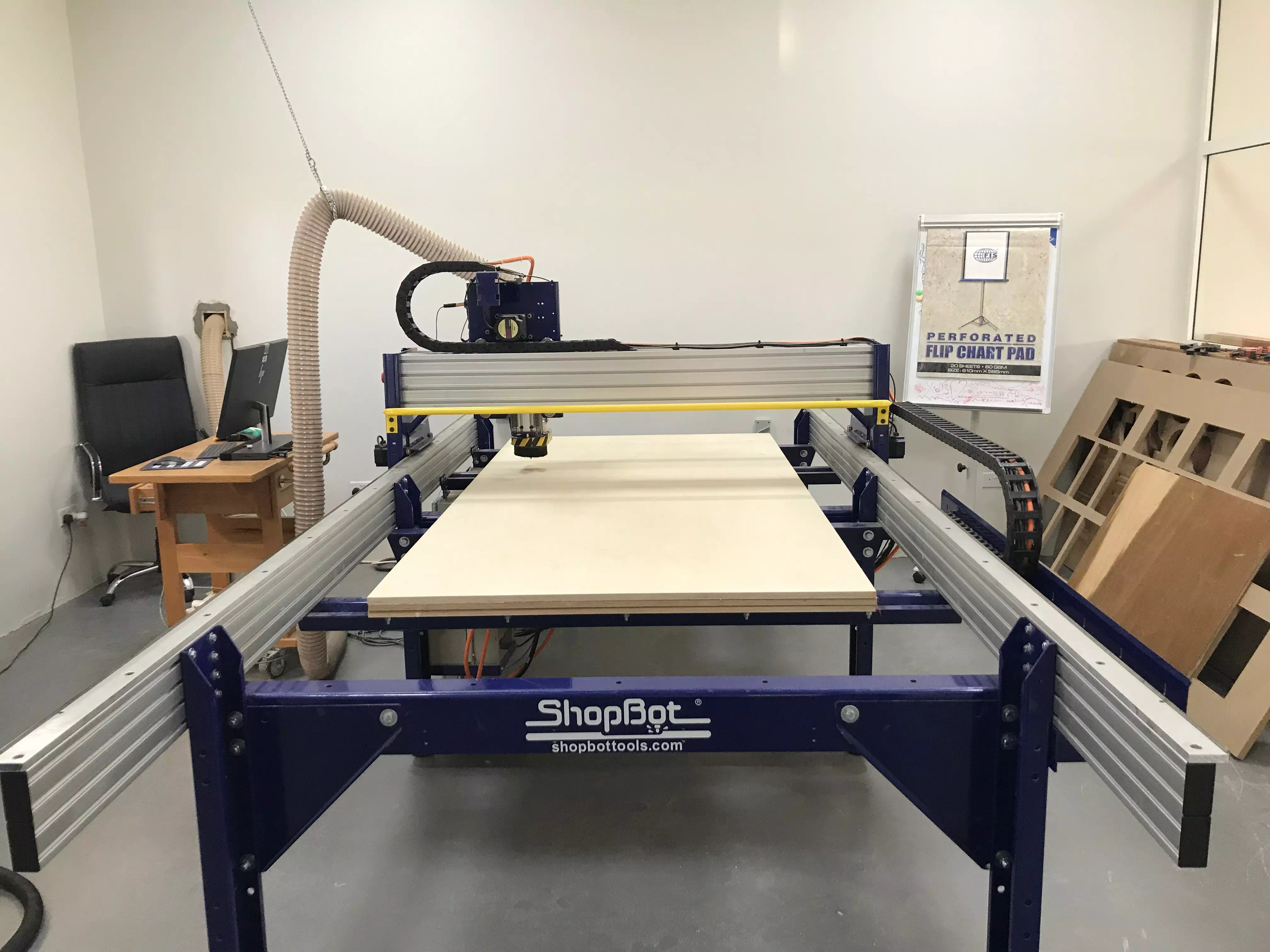
Clearance testing for cnc
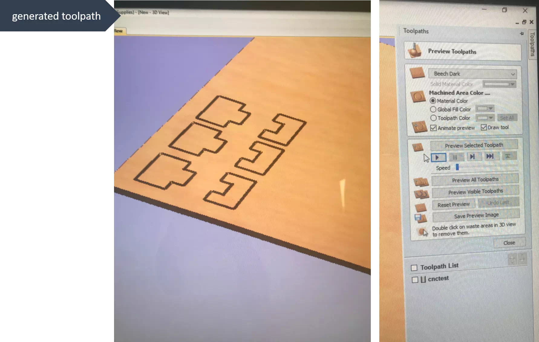
Now, the real work started! Choose 18mm wood and tool diameter 6mm. In addition, there is two new software’s that I learned to be use.1-Vcarve: I use it to import my drawing files as DXF files. Its useful to set the settings such as drill pit diameter, too path, cutting depth. 2- Cnc machine software which used to set the reference point and start cutting the parts.Let’s have some screen shots of the work:
Vcarve settings:
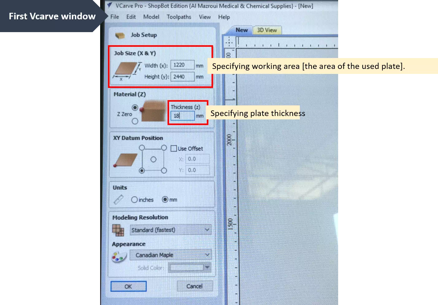
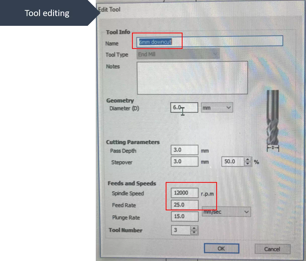
6mm downcut is the chosen tool. The spindle speed was 1200 rpm while the feed rate was 25mm/sec. Its necessarily to consider that as the spindle speed increased. The tool will be exposed to break due to over-rotation especially if it is not fixed well. In contrast, if the speed is very low then it will allow having more chance of fraction effect. This could lead to burning the workpiece. Moreover, the feed rate counts the removed material per time. If the rate is low, then the milling will take a long time. Thus, it would result in having smooth milled surface.
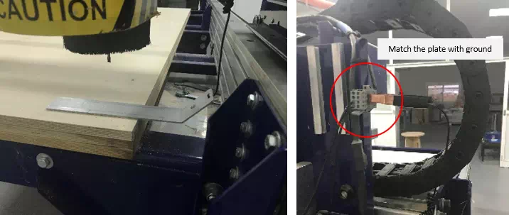
Machine setting
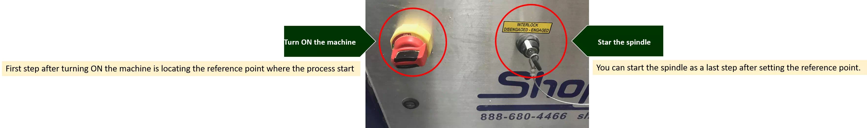
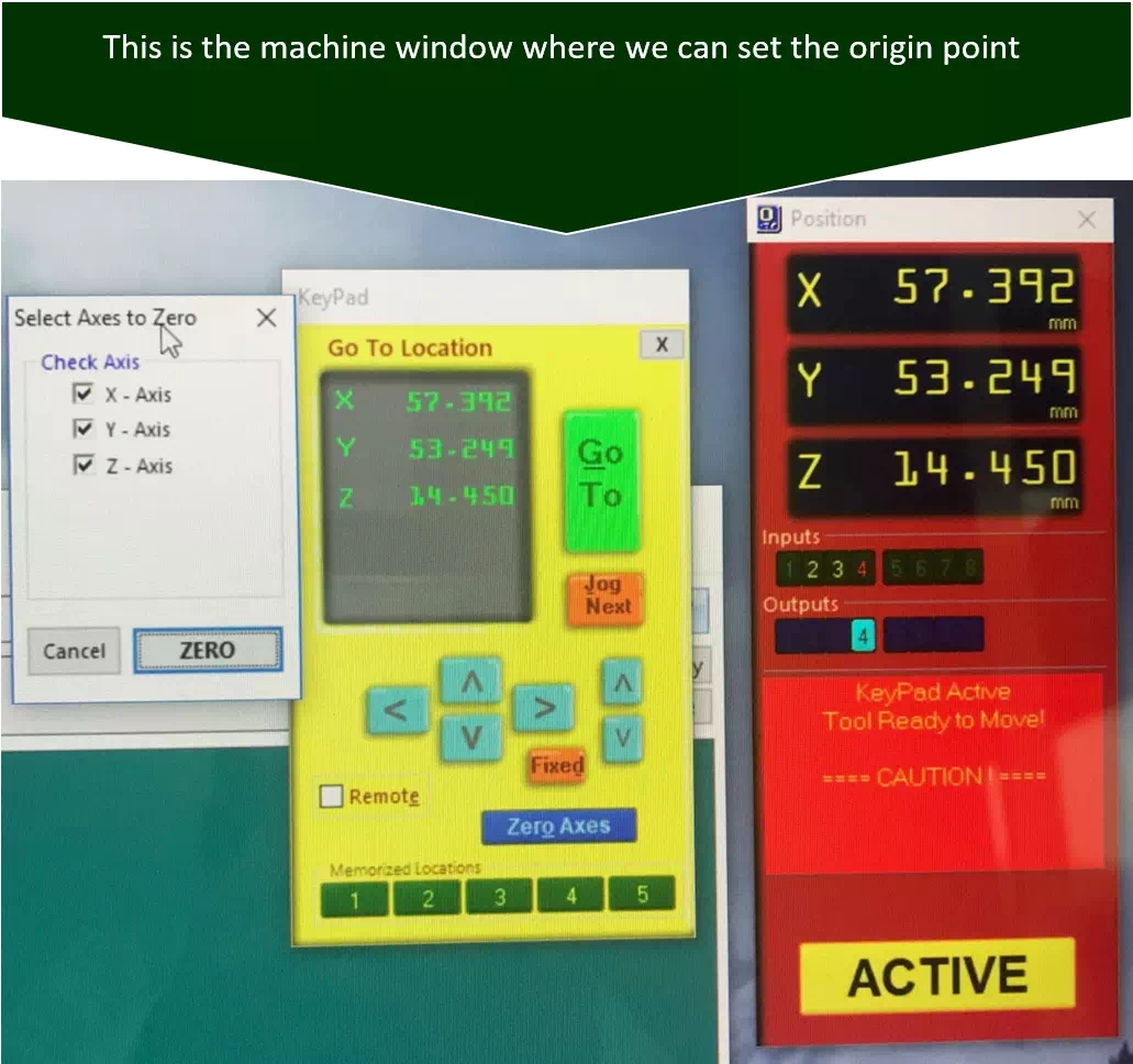
To set the reference point, x and y can be moved in the keypad window and the position located approximately. Whereas Z-zero has a different strategy. Few centimeters before touching the surface, a plate placed directly under the mill bit. Next, when choosing the button for z-zero the tool moves down to touch the plate. Then, it goes up and back to touch the plate for a second time. By this z-zero has been set. The machine knows the thickness of the plate so it considers the distance to the surface correctly.
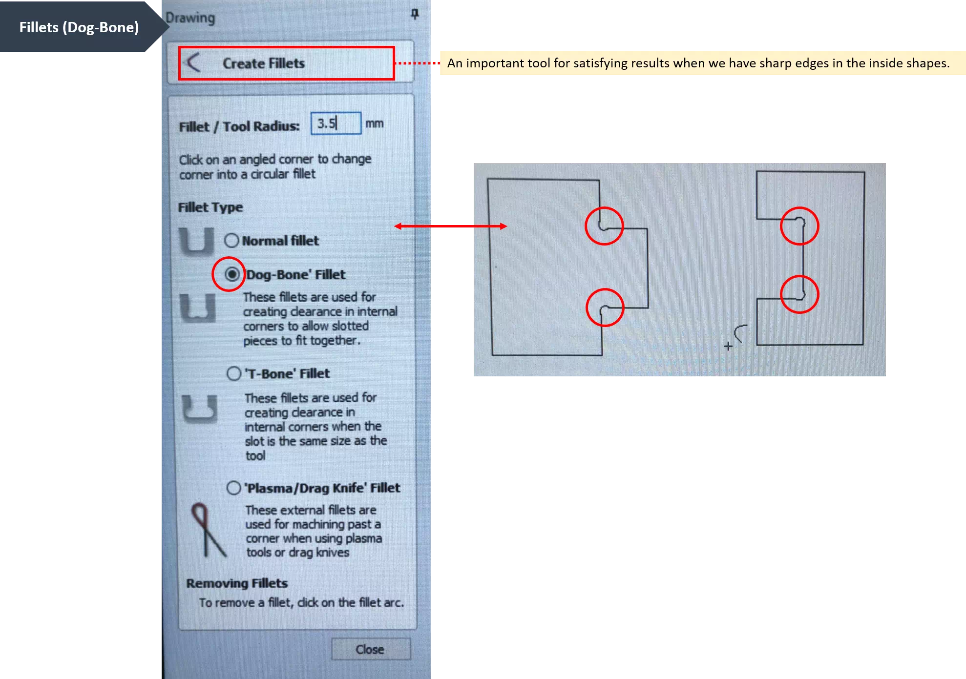
Well, I prepared simple joints design to know the machine clearance. It’s a group assignment before making our individual object. I used three different fitting sizes as shown in the following figures. After that I assembled the joints and decide which clearance is the best fitting.

The result showed that 0.2 was the best fitting so I will use it to fabricate my object.
Coffee table fabrication
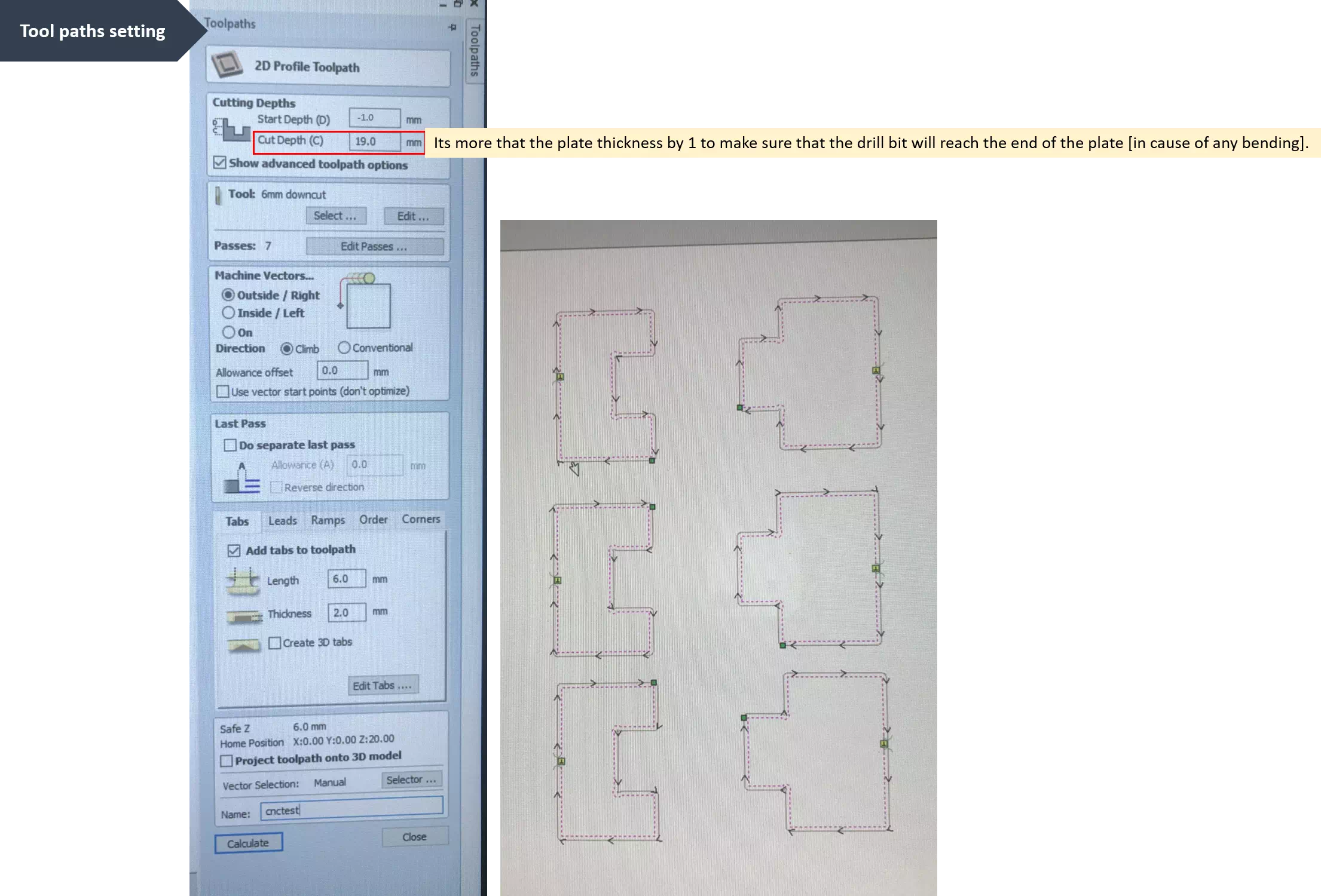
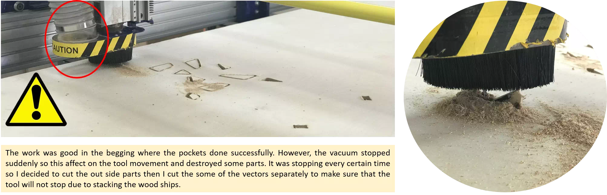
Now, I’m ready to make my table . There are three different tool paths for my table, first is the outside cutting, second is the pocking in the base and finally the inside vectors. I started cutting the vectors on the legs of the tables and unfortunately there was some issues I faced which are shown in the following figures:
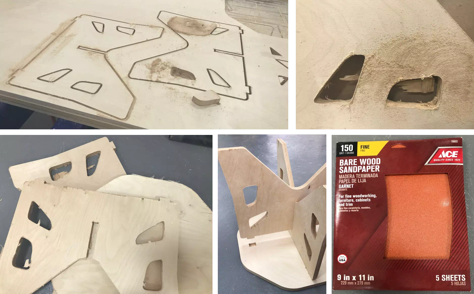
Finally, cutting the parts done successfully but they were still not ready for the assembly. A last step should be done was surface finishing and I used sand paper to clean the surface and make it smooth.
Congratulations!