Concept
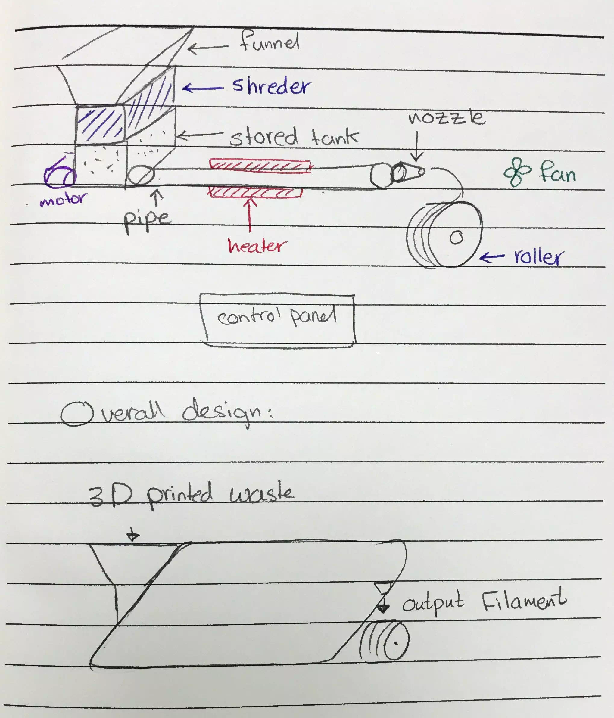
The future of 3D printing is widening and we should consider the number of parts that could be used again. Thus, I would like to design and fabricate extruder machine. The project will be an ecofriendly machine that support sustainable world and help in developing 3D printing sector.
Computer Aided Design (CAD)
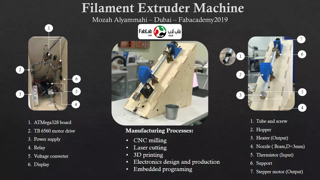
In this stage CATIA software had been used to make structure components. The table below presents the details each part.
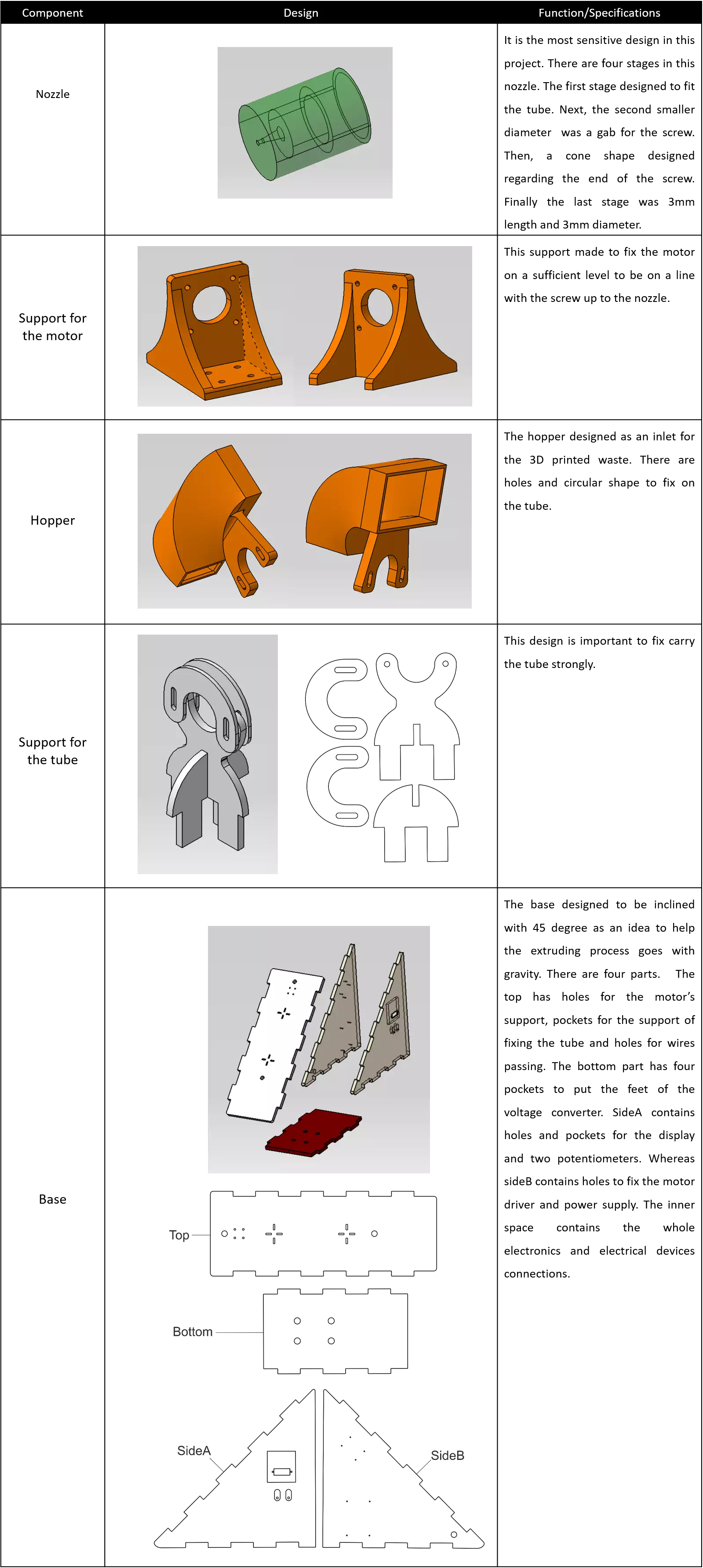
The electrical components like the motor, heater and tube were designed as well. The product design for the final project were containing overall the structure components and other parts which bought as shown below:

Computer Aided Manufacturing (CAM)
All the previous CAD components were made in the lab except the nozzle. It was made in a workshop outside the lab. The table below shows the manufacturing process techniques used for producing the structure components.
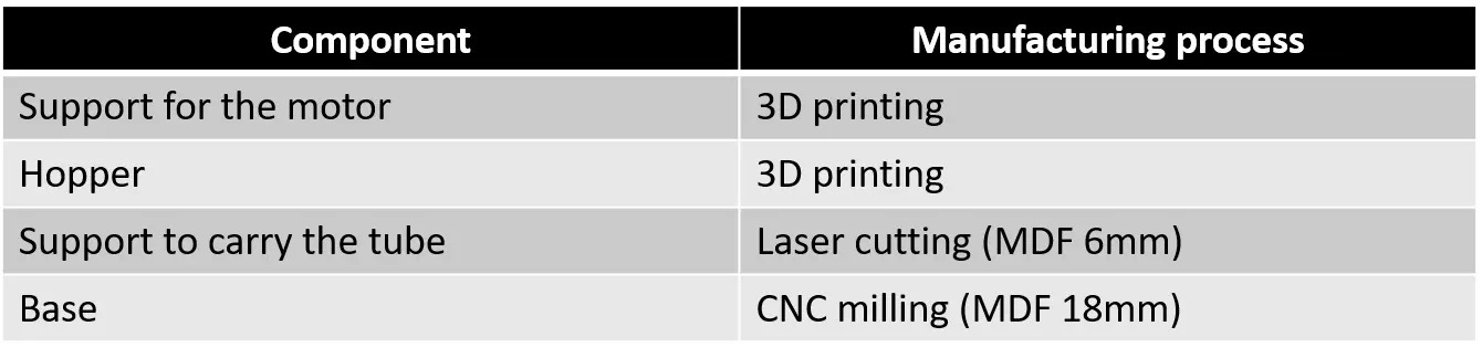
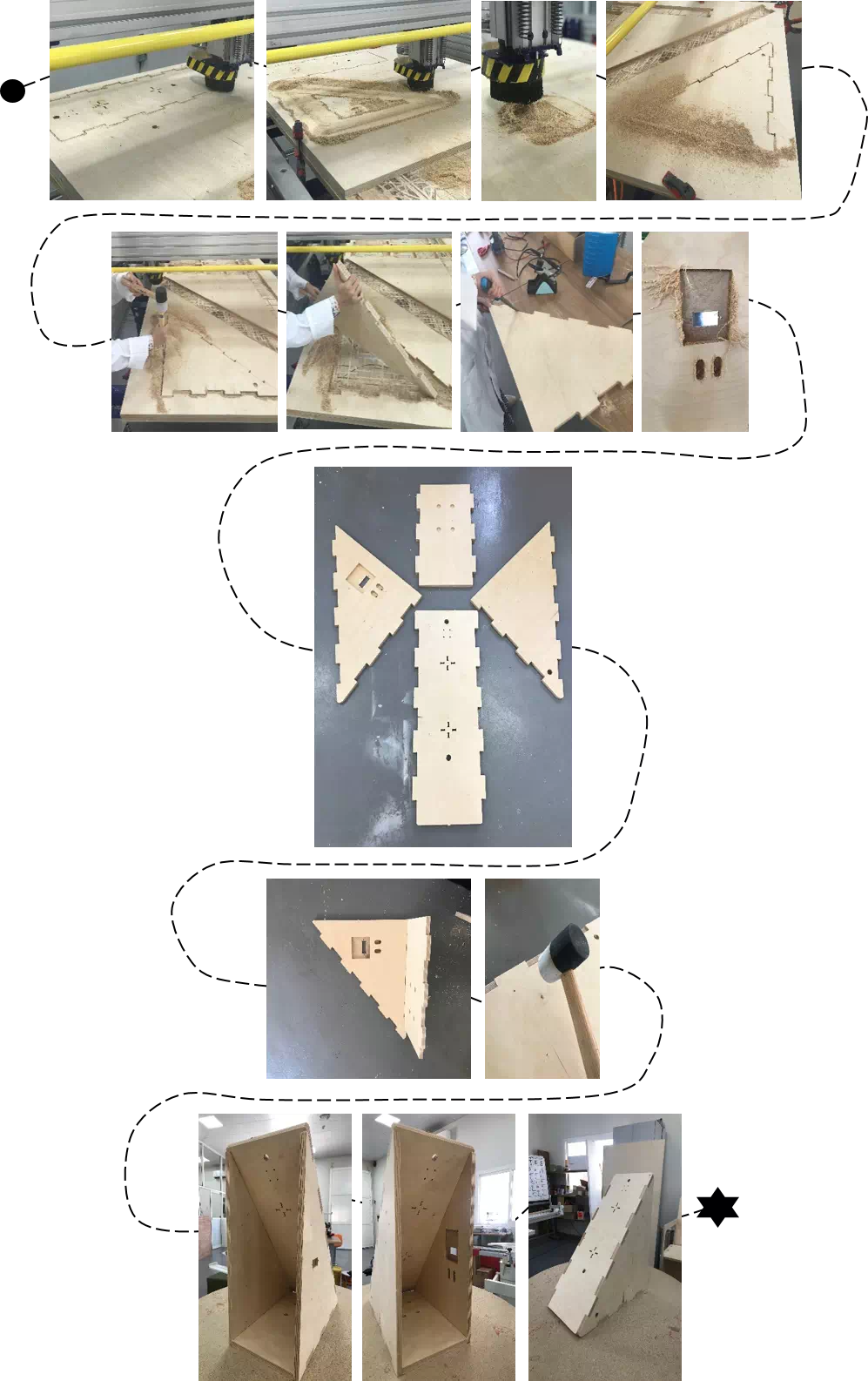
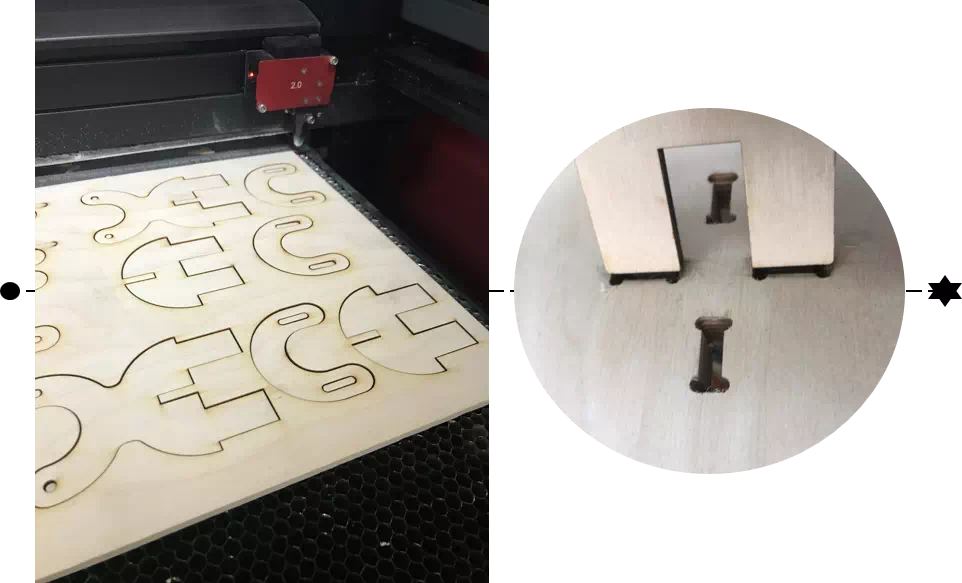
• CNC milling process
Shopbot machine used to make the base for the project. The material used is plywood with thickness of 18 mm as it is considered in the design. A smoothing tool used to remove the extra ships and provide surface finishing for each part. After that, the parts assembled to gather.
• Laser cutting
Two copies of supports for the tube were fabricated by laser cutting machine. The material used is plywood with thickness of 6 mm as it is considered in the design.
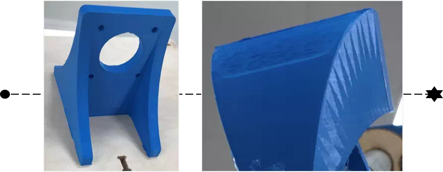
• 3D printing
Complex shapes were produced using 3D printing technology. The procedure of making the part is the same as in week6. As shown below, the motor’s support has curved sides to provide more stability. In addition, the hopper were designed in curved shape to allow the parts enter easily.
• Electronics
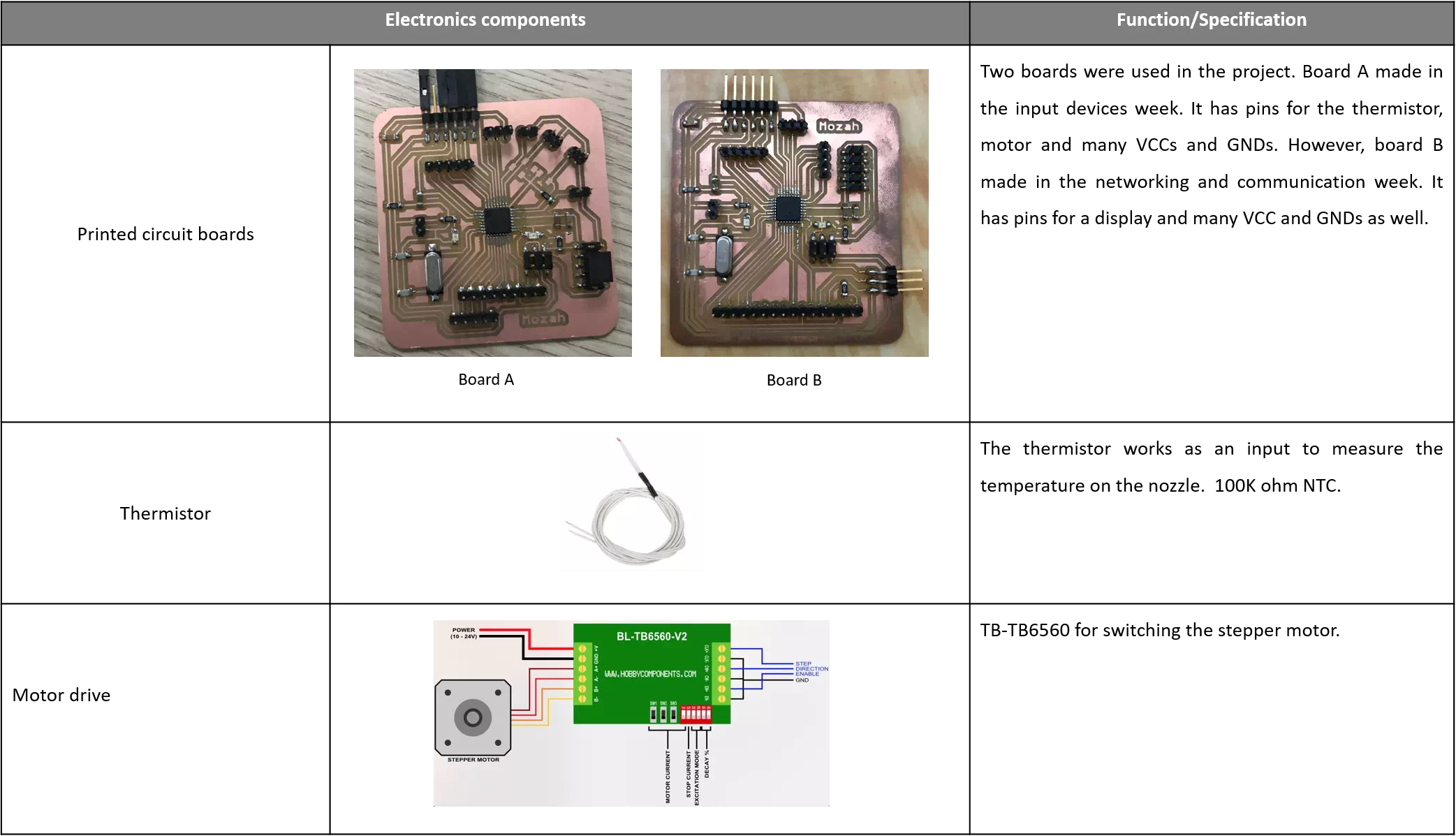 Board A from input devices week
Board B from networking and communication week
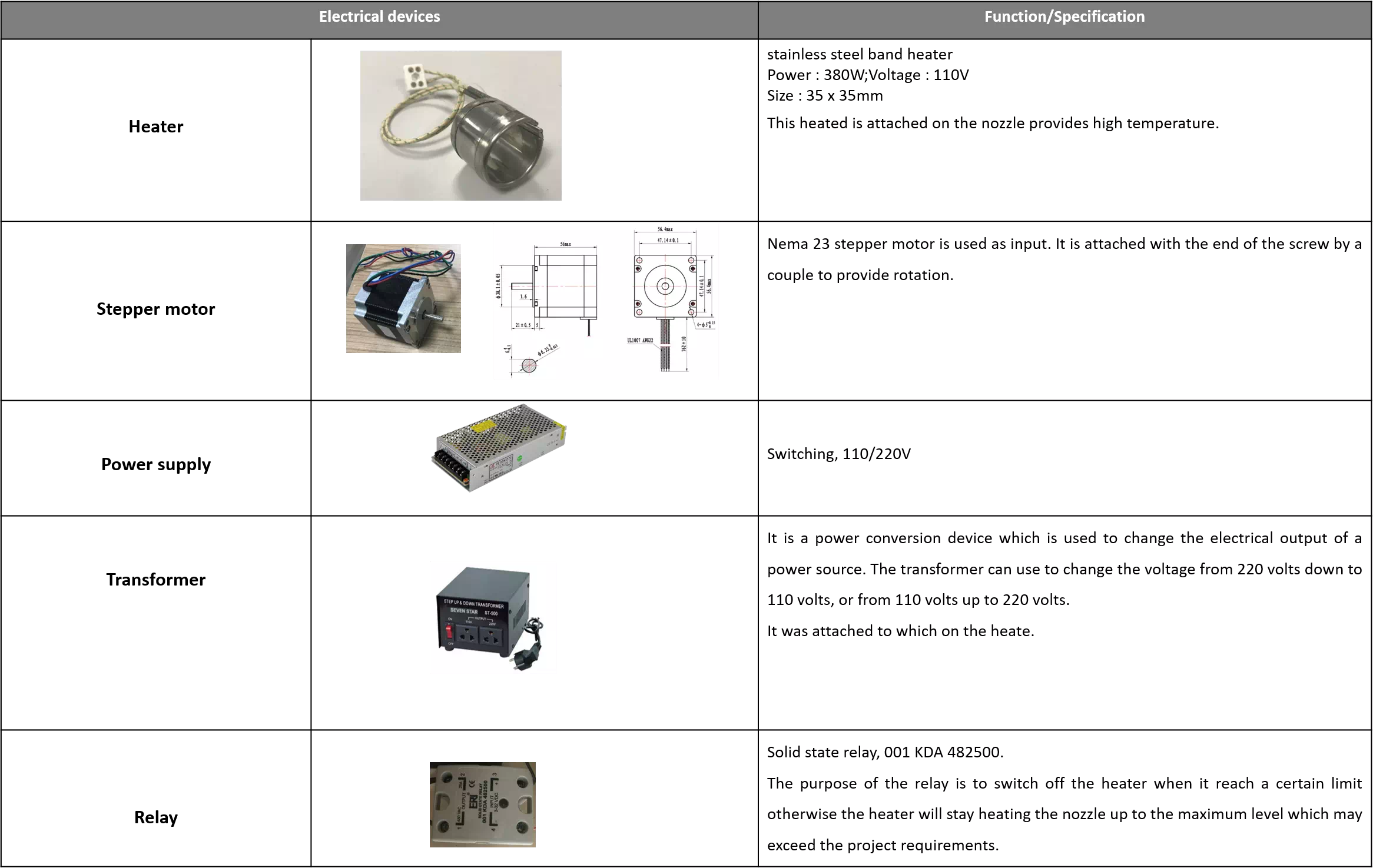
• Electrical Devices
Embedded programming
After collecting the whole project parts. Now the software started. There are two codes merged to gather. The first code was for the thermistor which the same one used in the input devices week. The second code was for controlling the motor which the same code used in the output devices week. The motor connected with a motor’s drive with four wires to run it. Then the drive was connected with the board by the pins: Direction, Step, enable, VCC and GND. Setting the direction is important to rotate the screw on a correct direction in order to push the filament out. Therefore, decreasing the steps of the motor was useful to decrease the vibration.
Both codes merged to gather to get an input temperature from the sensor, run the motor and control the heater.
        //Temperature sensor
int ThermistorPin = A0;
int Vo;
int PWM=8;
int Heater=3;
float R1 = 100000;
float logR2, R2, T, Tc, Tf;
float c1 = 1.009249522e-03, c2 = 2.378405444e-04, c3 = 2.019202697e-07;
//MOTOR
int x;
#define BAUD (9600)
void setup() {
Serial.begin(9600);
 pinMode(Heater,OUTPUT); // HeaterOutput
//MOTOR
Serial.begin(BAUD);
  pinMode(6,OUTPUT); // Enable
  pinMode(7,OUTPUT); // Dir
  pinMode(5,OUTPUT); // Step
  digitalWrite(6,LOW); // Set Enable low
}
void loop() {
Vo = analogRead(ThermistorPin);
Serial.print("voltage: ");
Serial.println(Vo);
  R2 = R1 * (1023.0 / (float)Vo - 1.0);
  logR2 = log(R2);
  T = (1.0 / (c1 + c2*logR2 + c3*logR2*logR2*logR2));
  Tc = T - 273.15+54;
  Serial.print("Temperature:");
  Serial.print(Tc);
  Serial.println(" C");
if (Tc < 250 && Tc>0)
{
analogWrite(Heater,PWM);
}
else if(Tc >= 250)
{
digitalWrite(Heater,LOW);
}
if (Tc>200)
{
digitalWrite(6,LOW); // Set Enable low
  digitalWrite(4,HIGH); // Set Dir high
  Serial.println("Loop 200 steps (1 rev)");
  for(x = 0; x < 5; x++) // Loop 200 times
  {
    digitalWrite(5,HIGH); // Output high
    delayMicroseconds(10000); // Wait
    digitalWrite(5,LOW); // Output low
     delayMicroseconds(10000); // Wait
  }
  //Serial.println("Pause");
  }
//delay(500); // pause one second
}
As shown in the code above PWM (Pulse Width Modulation) was used. It is a technique for getting analog results with digital means. PWM is a method of reducing the average power delivered by an electrical signal. On other words, it is useful to get analog output with digital means. In this project the relay was activated by using PWM signal to control the heater for the nozzle.
Therefore, to control the temperature range and avoid overheating. If statement was used to set the acceptable temperature range between 250C and zero. Thus when the temperature equal or more than 250C the heater will stop the heating.
Final result
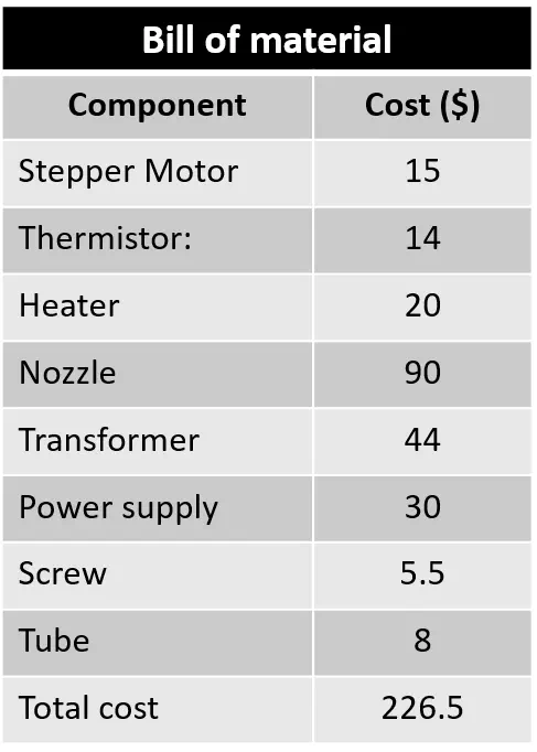
Bill of material
License for copyright
Actually, this is my first time to use a copyright. A Copyright License provides a contract under which a copyright owner allows another person to use the copyrighted material. Creative commons is a good choice which provide a steps to choose the suitable license. I would like to share my work with others.Thus my project is licensed under a Creative Commons Attribution 4.0 International License .