Task required:
We assigned to redraw the echo hello-world board, add at least a button and LED ((with current-limiting resistor). Fabricate it, program it and test it.
what I did ?
- Redraw hello-world board using Eagle .
- Prepare traces image and outline image using GIMP
- Transfer the images from PNG to RML format using fabmodules website
- Fabricate the board using milling machine.
- Solder the components.
- Test the continuously using millimeter to check my soldered connections.
- Program the board.
Procedure
Before starting I reviewed Neil’s board connection and components then I listed the components that I will use in my board design. Well, I the components I need are:
- 1. Attiny 44
- 2. ISP Header
- 3. 10K ohm Resistor
- 4. 499 ohm Resistor
- 5. 20 MHz Resonator
- 6. FTDI Connector
- 7. 1 uF Capacitor
- 8. Push Button (6 mm x 6 mm)
- 9. LED 1206
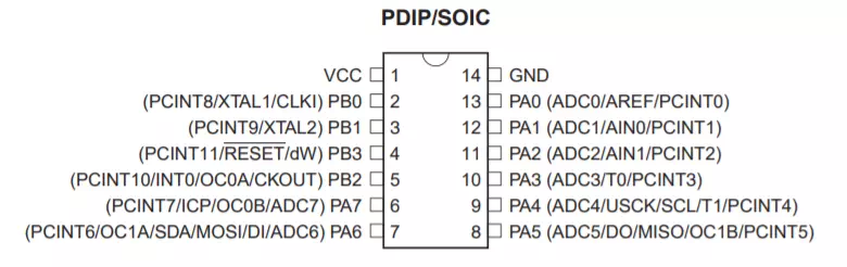
ATtiny 44
Before redraw the echo hello-world board, some theoretical knowledge must be consider. It is important to refer to the datasheet to understand the pins and overall layout of the microcontroller. The screenshot below presents the pinout of Attiny 44 such as VCC and GND. There are ports A that are used as analog pins. In addition, there are ports B which considered as digital inputs.
Digital pins are able to "understand" only two levels of signal, LOW or values close to 0 V and HIGH or values close to 5 V. On the other hand, the analog inputs are capable to read voltage values from 0 to 5 Volts.
Now, to add the button and LED. The push button is an input and must be connected with GND in one side. In contrast, the other side should be connected to a I/O pin. Once the button is pressed (closed connection), the Arduino reads LOW because the input pin is connected to the ground. However, when the button is released (open), Arduino reads HIGH which means the input pin is connected to 5V.
One side of the LED must be connected with ground and the other one to a digital pin. Note, an LED is a diode and a diode is requires a voltage of 1.8V~3.3V to operate. However, the VCC’s provides 5volts which exceed the LED’s capability to be powered. Thus, the LED would burn. In order to solve this problem and reach acceptable voltage range a resistor is needed to drop the voltage from 5V to 3.3V. Usually, the LED consumes a current of 20mA. Ohm's Law ( V=IxR) is used to determine the required resistance. Given: V=5Volt, I=0.02A so R=250 Ohms.
The resistance should at least 250 Ohms or higher to drop the voltage. Depending on the available resistances as standards, the nearest value is 499 Ohms which is more than enough to ensure that the voltage is dropped as its required.
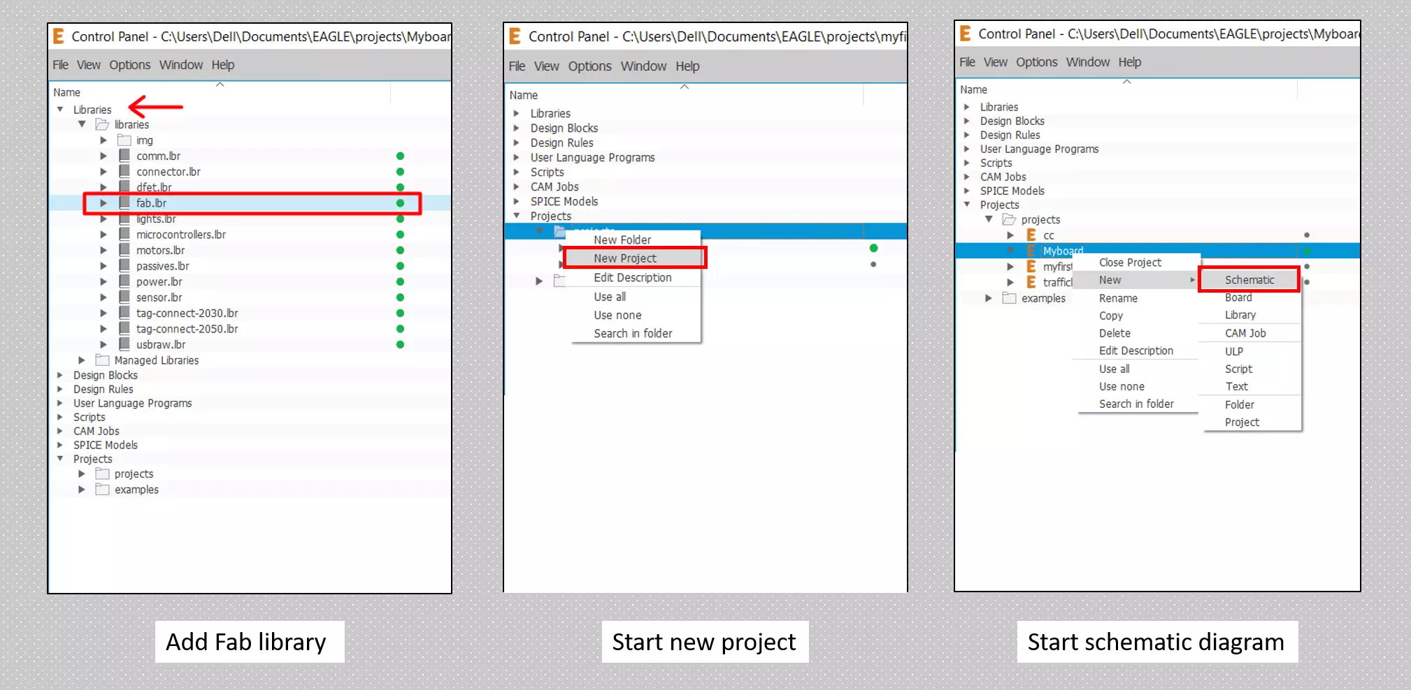
Design the board
This is my first time to use an eagle to design my own board. I was so excited since I’m learning new software and new skills in electronics. So far I would like to share some highlights for using the software. I created an account in Autodesk as a student to download Eagle on my laptop. Then I added Fabliberary which consist list of components that provided for fab students. Therefore, to start designing we should start a new project and go to the schematic window. The following figure summarizes the highlights I mentioned.
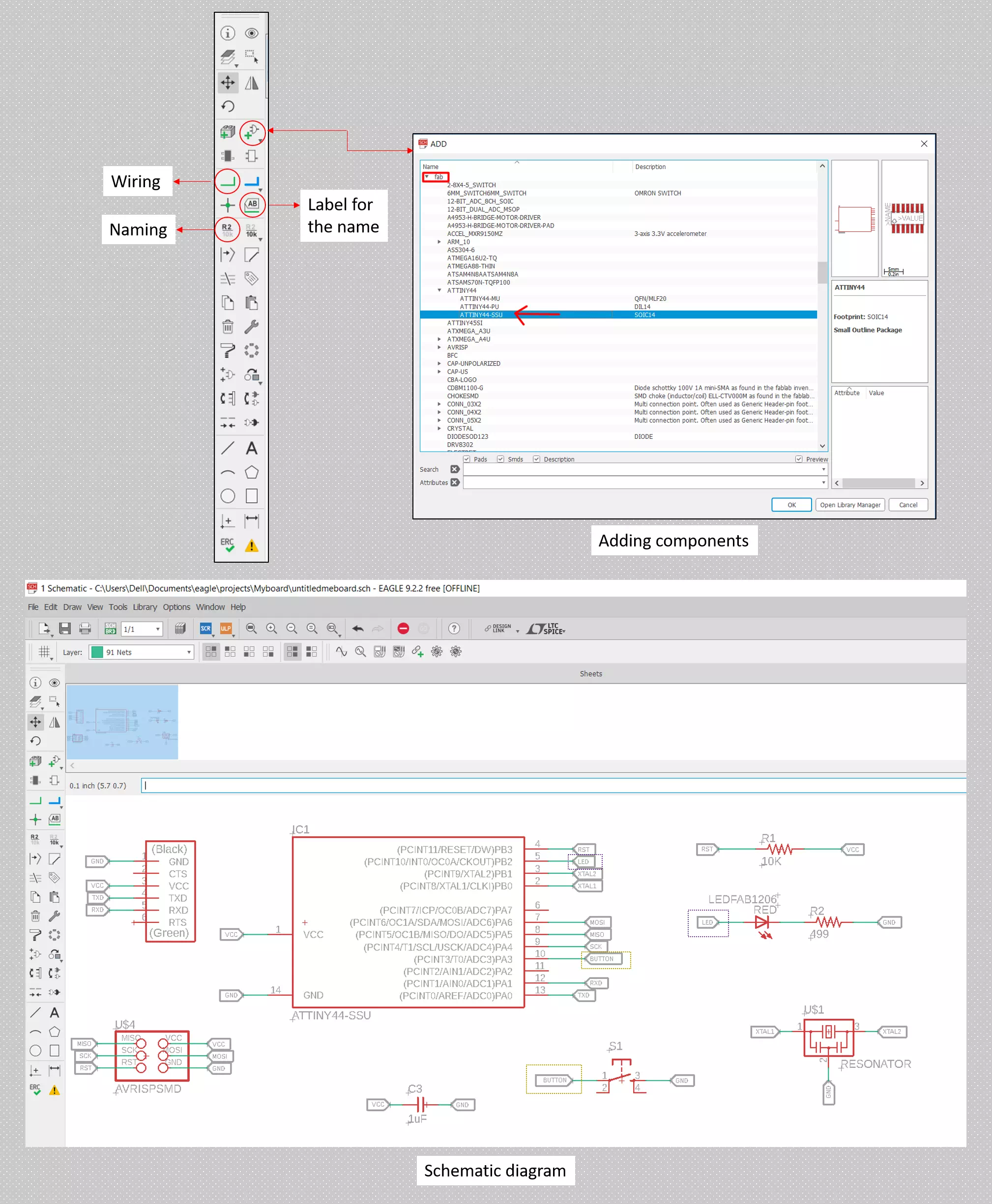
Now in the schematic window, I draw my circuit connection and added the components as shown in the figure below:
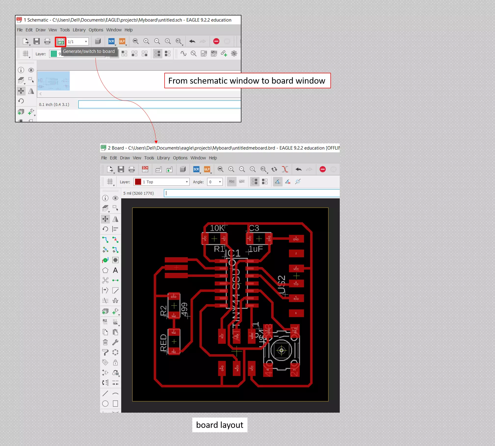
After putting the components and specifying the whole connections I went to board window and there I located every item as a designing for my board. Furthermore, I did two steps before finalizing my board design as presented in the figures below:
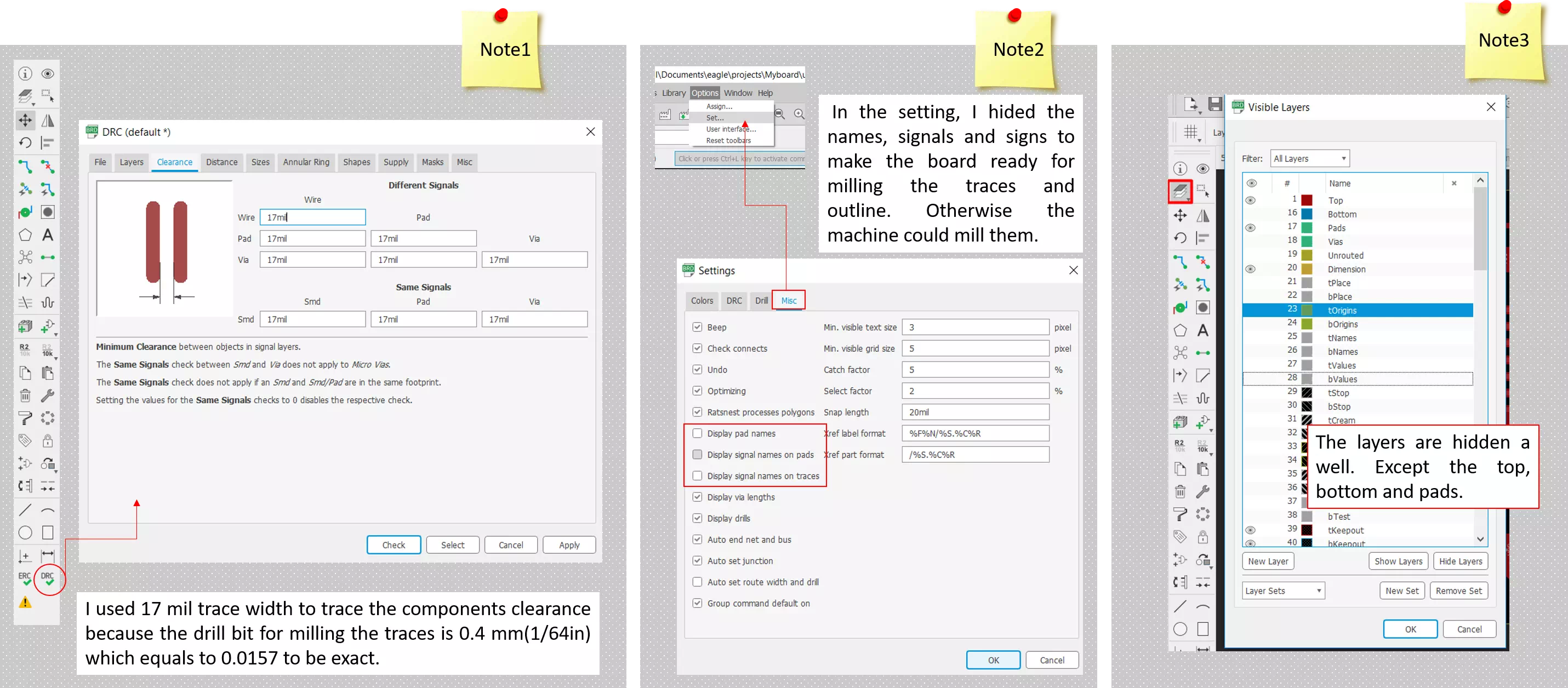
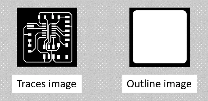
Finally, I saved the image by File>export>image [√Monochrome]. Now my board image is ready as shown below this is my final design where I modified them in GIMP to create the outline image.
Milling process
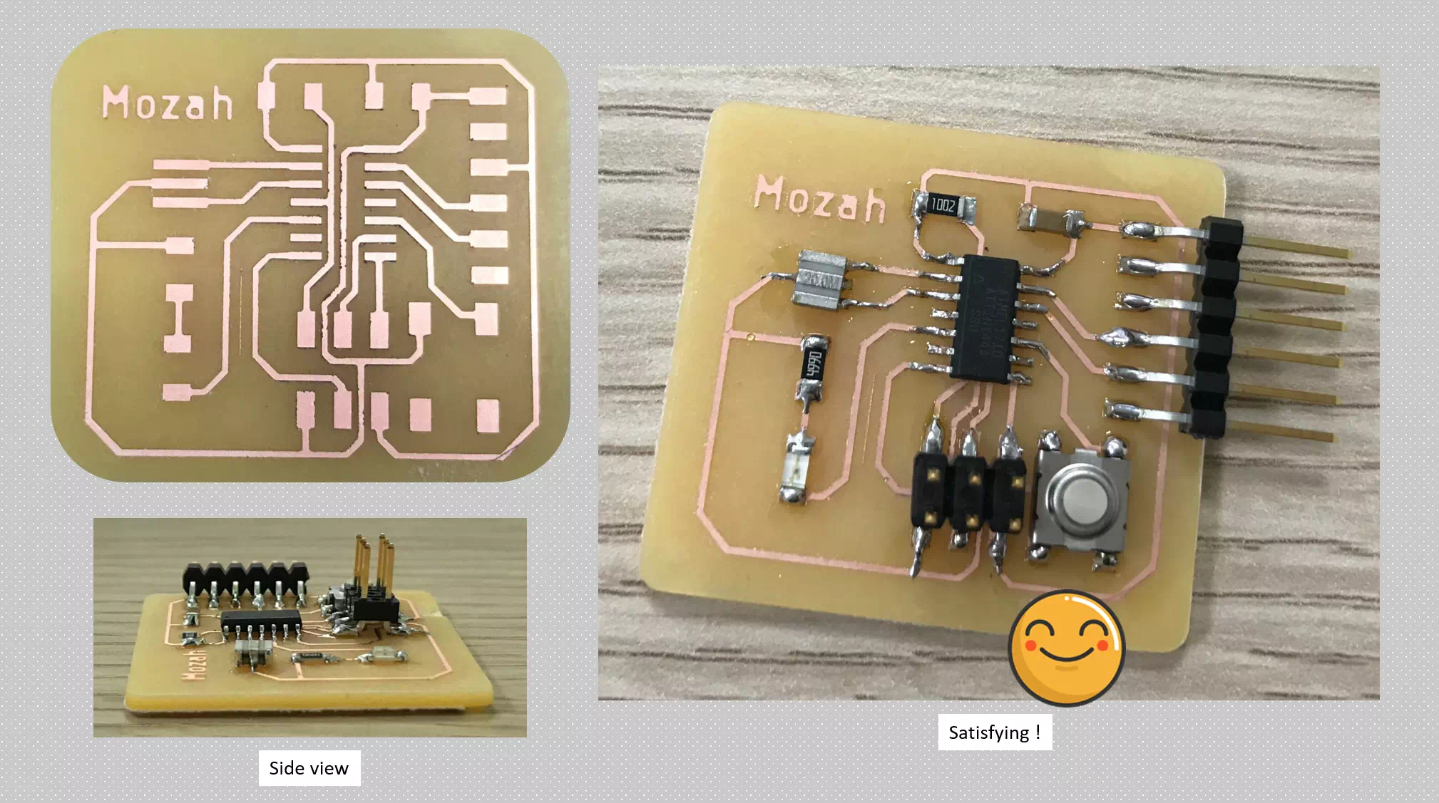
To start milling I used fabmoduls to prepare my images format. I repeated the same steps as in week3. Note, it is necessary to check the polarity of the LED before soldering. Most surface mount LEDs have a line indicating the cathode - the negative polarity in a green line. Using the multimeter, if the polarity is correct LED should light up in the continuity test mode.The figure below show my board after milling:
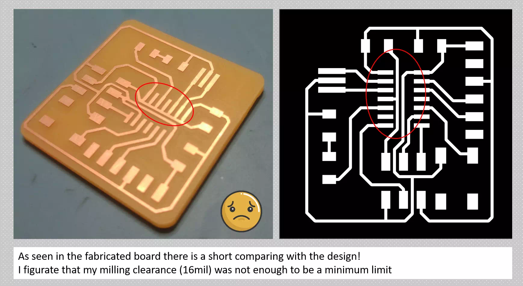
Well, I decided to modify my design and put 17mil clearance to ensure that there is no short in my circuit. Finally, I mill it and solder the components as well as I check the continuous by multimeter and it was satisfying.
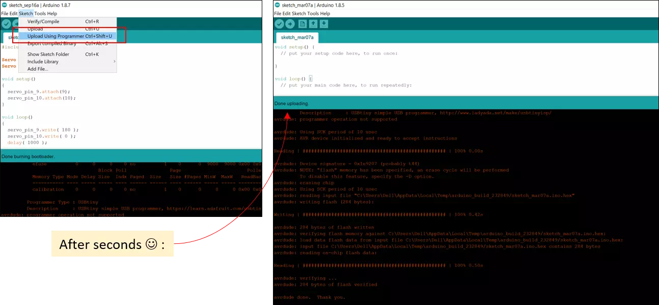
Programming the hello board
The programming process will be by connecting the USBTiny board that fabricated in week 5 with the newly echo hello-world board. As my first time using Arduino software I applied the guide in Tutorial to support me. The following steps present my steps:
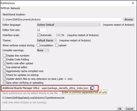
- Go to File>Preferences and paste the link : https://raw.githubusercontent.com/damellis/attiny/ide-1.6.x-boards-manager/package_damellis_attiny_index.json
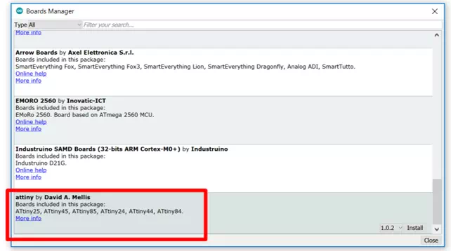
- Got go to Tools > Board menu > Board manager. Then search for Attiny44 and install it.
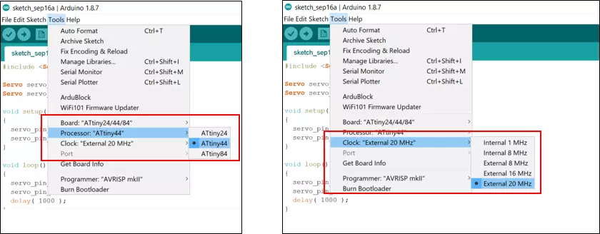
- Close the board’s manager. You should now see an entry for ATtiny in the “Tools > Board” menu:
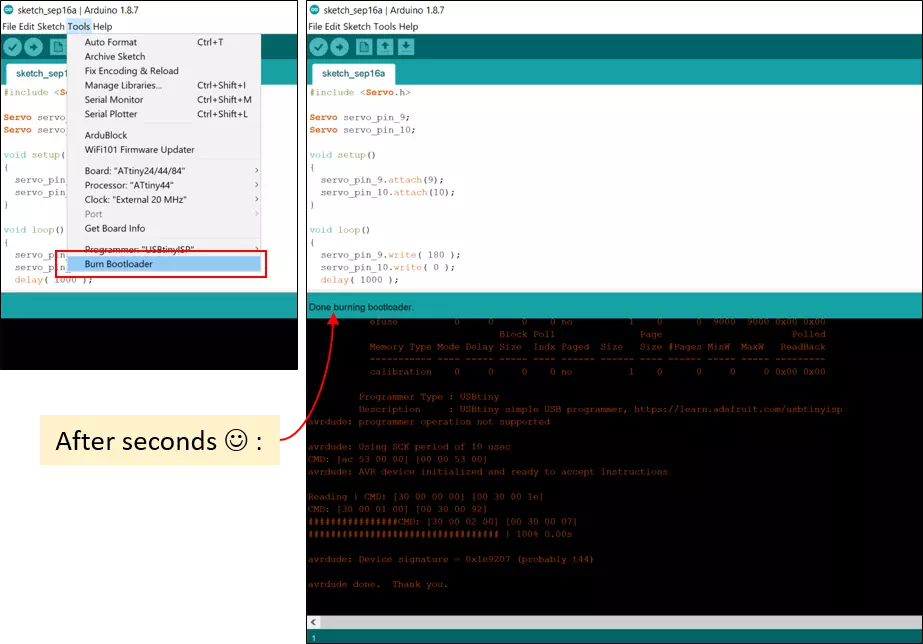
- Now, upload the programming: