What I learned?
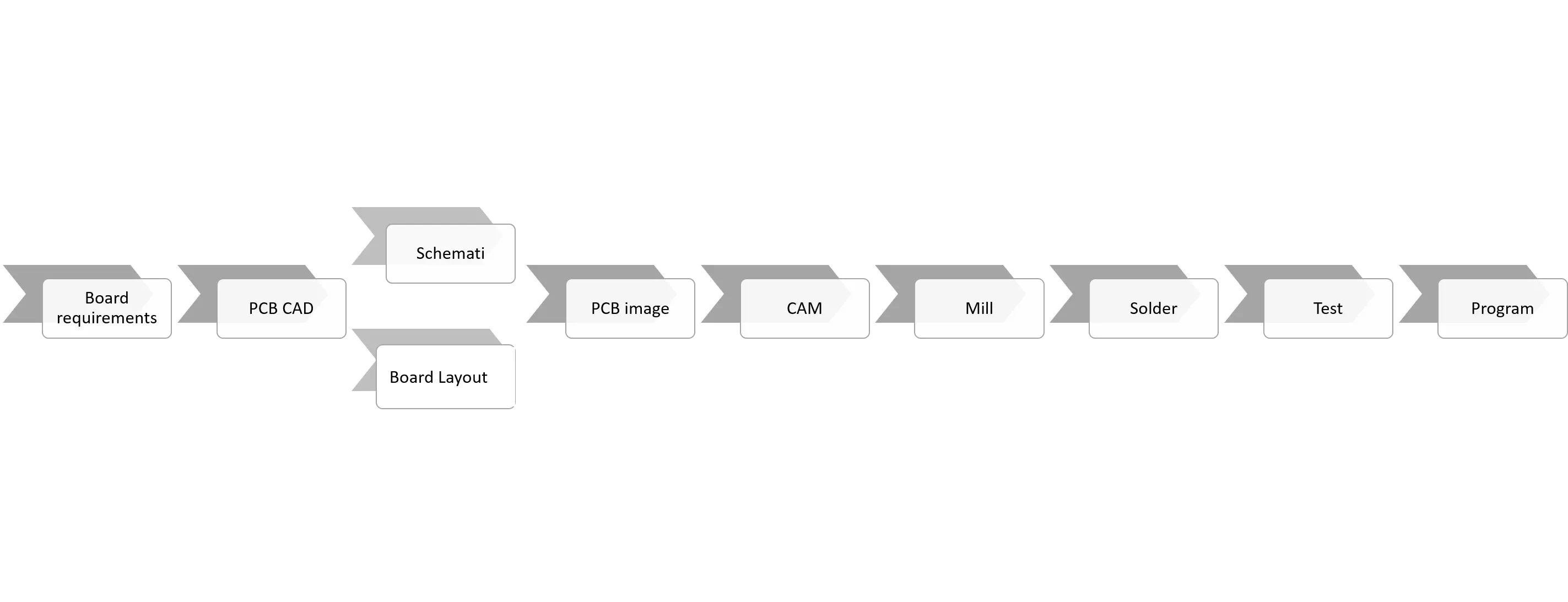
In this week we introduced to electronics production techniques in order to build electronic circuits. In electronic production we can produce printed circuit board (PCB) including the PCB itself, soldering the components as well as the programming of the digital electronics. There is many different techniques in electronics products such as surface-mount technology (SMD, etching, sewing, electroplating, milling, fiber laser, and vinyl cutter. Also, there are a number of PCB materials such as FR1, Aluminum, paper, and cardboard. In addition, I learned a great flow work technique for making a PCB as shown in the diagram below:
Task required:
We assigned to fabricate PCB which is FabISP. It is a ready version board that can be produced in a fab lab and in this assignment we are going to start from computer-aided manufacturing (CAM) step.
what I did ?
- I downloaded the PCB images from the previous tutorial link
- Prepared my board using milling technique.
- List the components and do soldering
My procedure:
PNG image
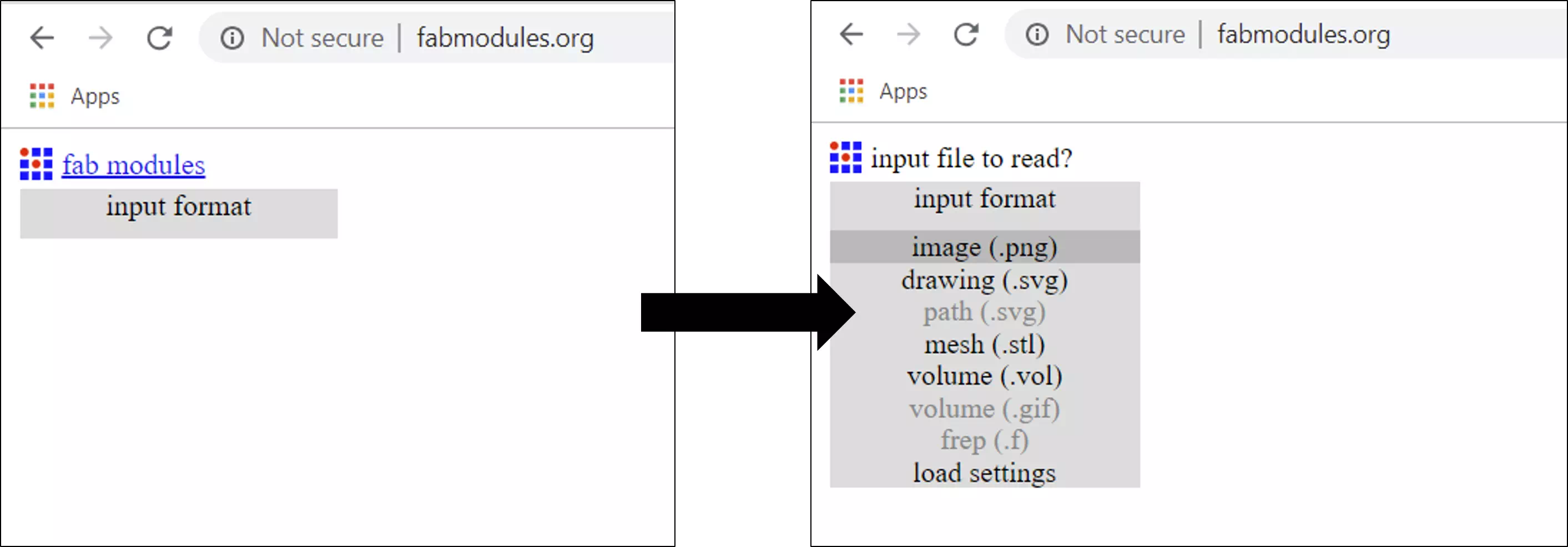
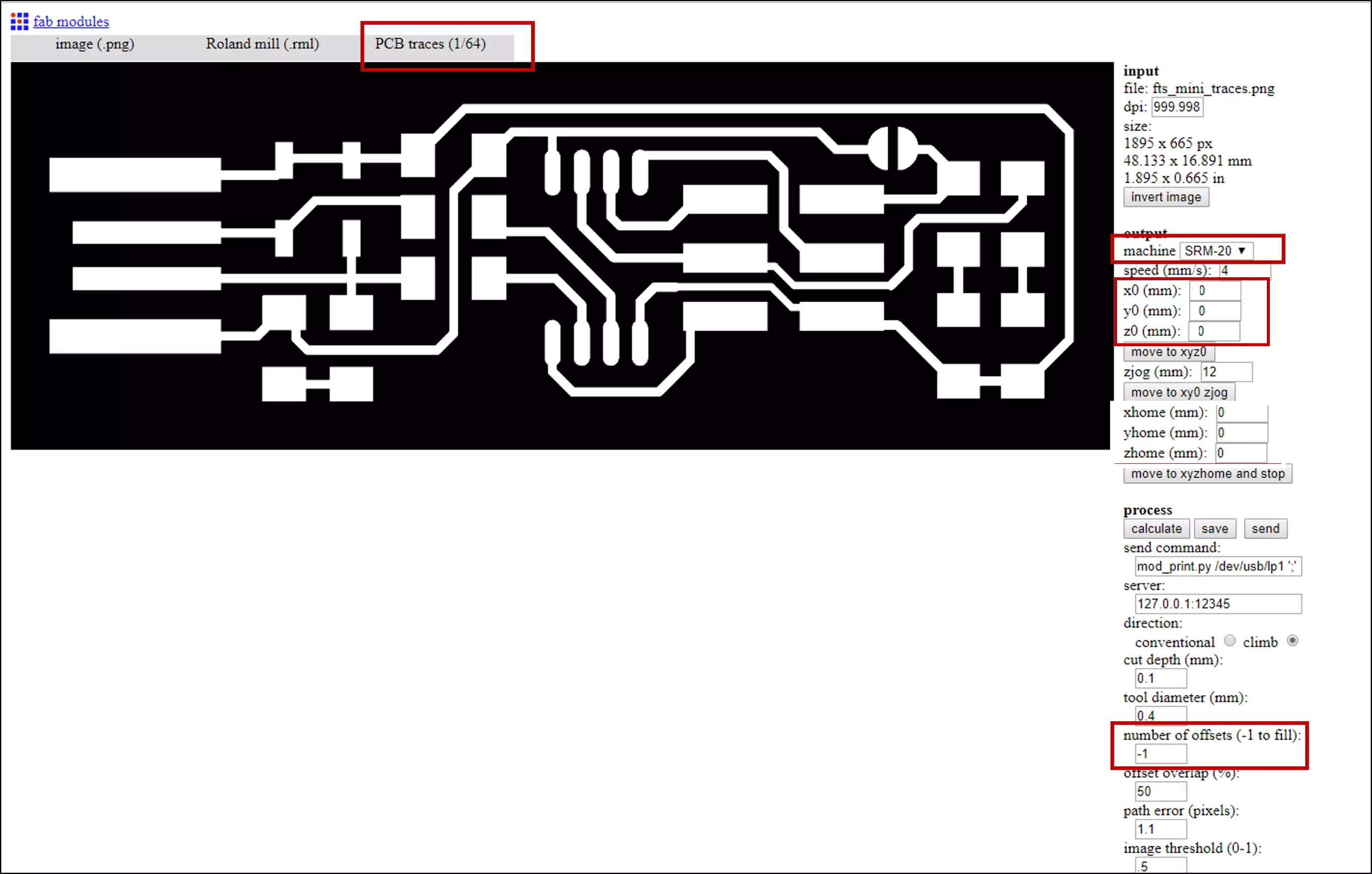
- I Went to Fabmodules . In addition I chose the input format as PNG
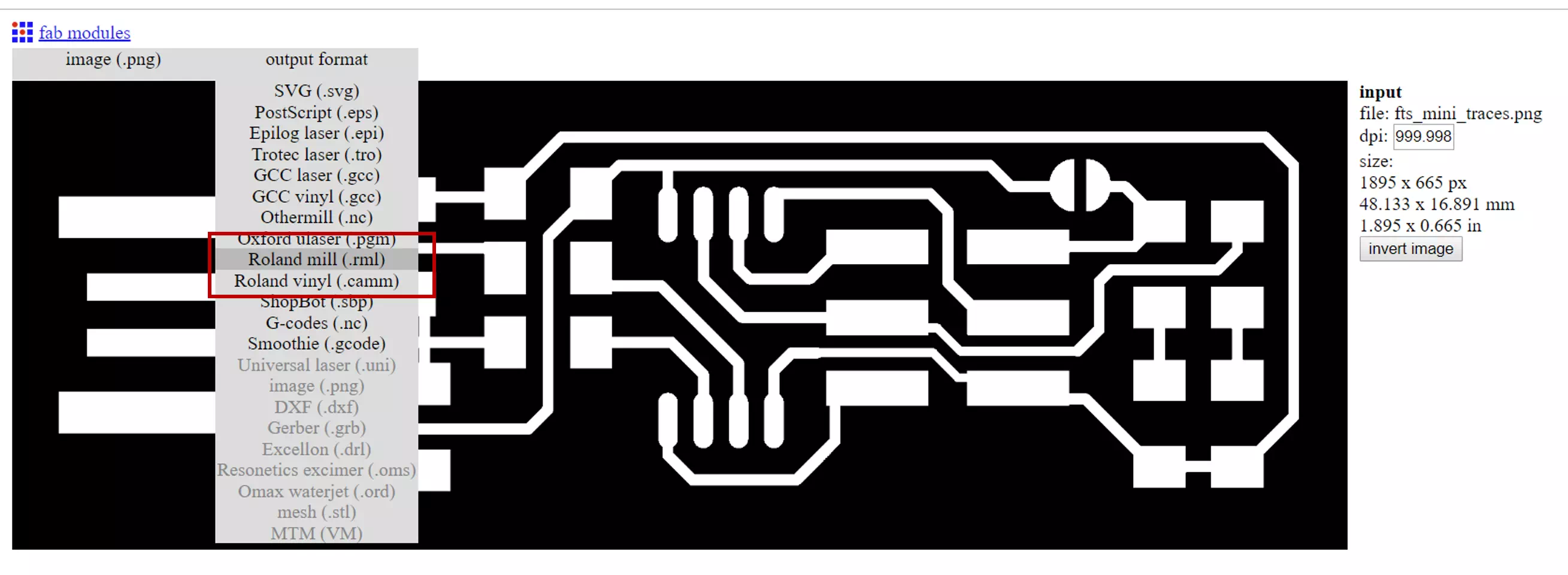
- Now, choosing the output format for the traces image as Roland mill which is the name of the machine that I will use for the milling process. Note: traces: a continuous path of copper on a circuit board.
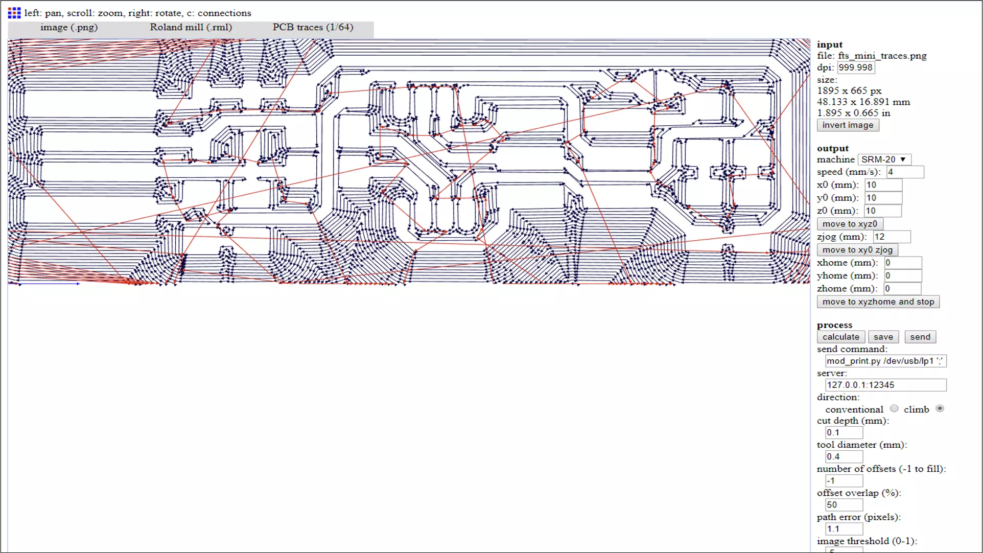
- Then, the PCB traces process as (1/64) which is the size of milling the path of the traces. In addition, an important point must be modified in this step: Machine: SRM-20 which is the type of the milling machine. X,y, z reference point zero. NO.offsets: -1
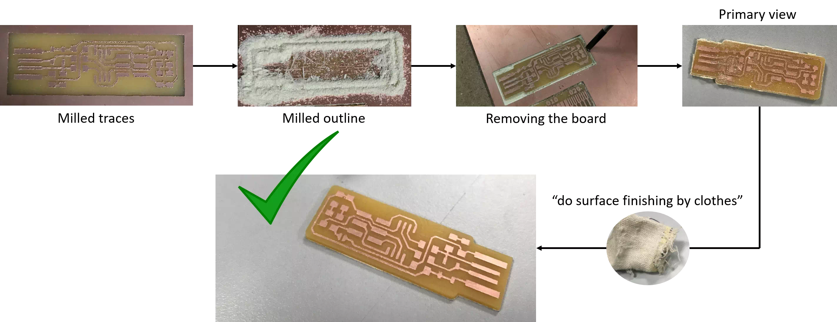
- Next is calculate and wait minutes until it finishes and presented as the figure below. Then save and open the file in the machine software.
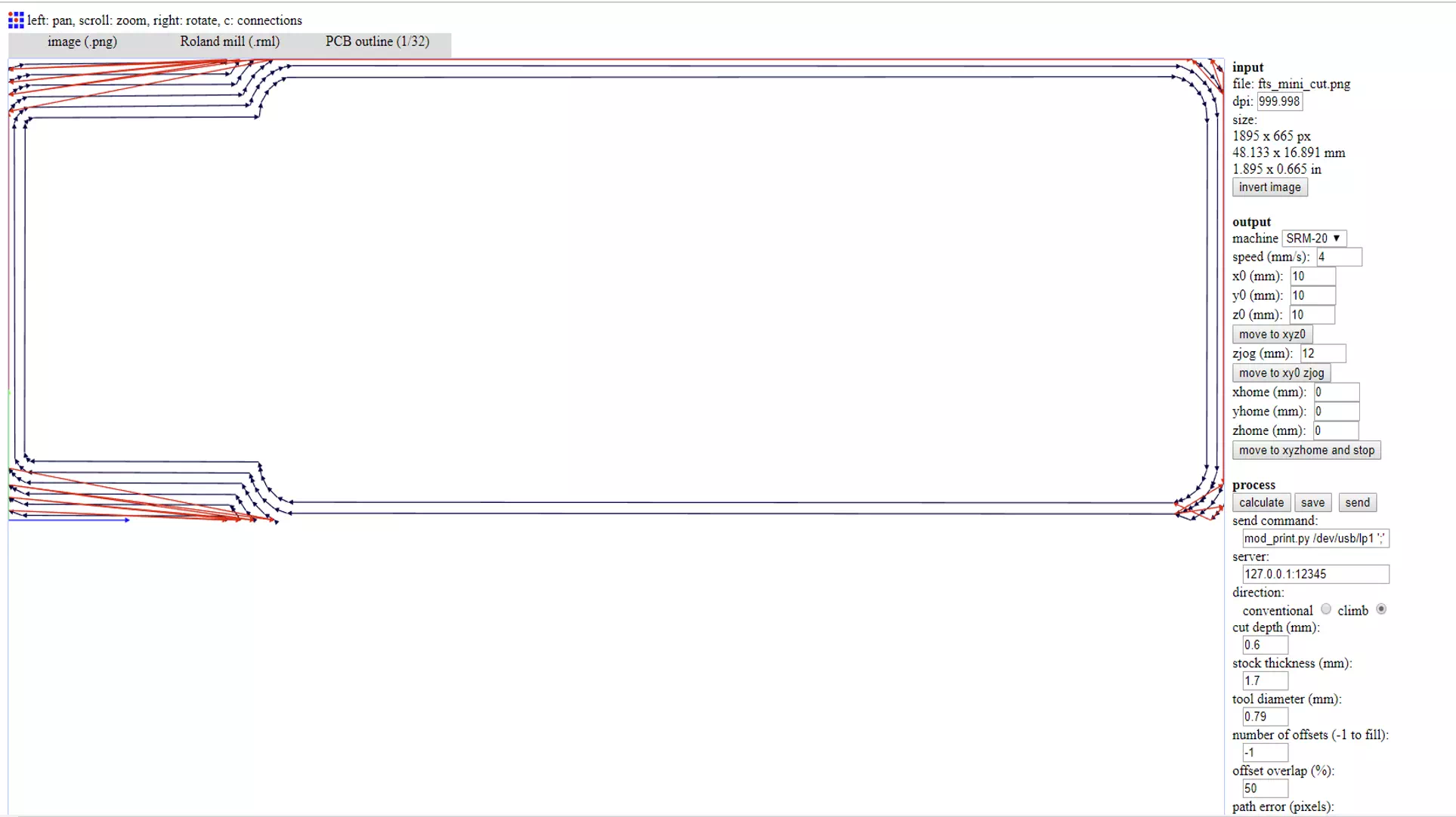
- The same steps repeated for the outline image traces which is the outer cut line for the PCB except in the process its outline 1/32. The result for the outline image shown below:
Mill
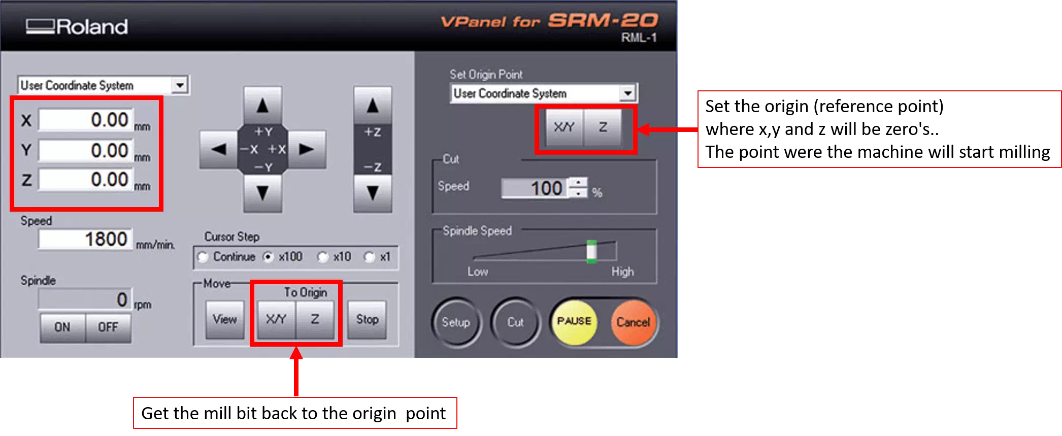
Now my PCB images are ready to fabricate. I installed the raw material in the milling machine as well as mill bit with the size of 0.4mm which is the traces image. In addition, the figure below present Roland milling machine SRM-20 software. Notice that for setting the reference point: Move x and y-axis to a suitable position and make sure that you have enough area for your piece. Move z-axis until it touches the surface but be careful to do not damage the mill bit so for safety you can touch do that manually when the bit becomes very near the surface open it manually and let it be touch. Then press on the XY and z bottoms right top in the software to set the origin point. Now we have starting point press cut, choose your image file then output.
The milling was first for traces then I repeated the same setting steps for the outline cut. The following figures summarize the next steps:
Solder and test
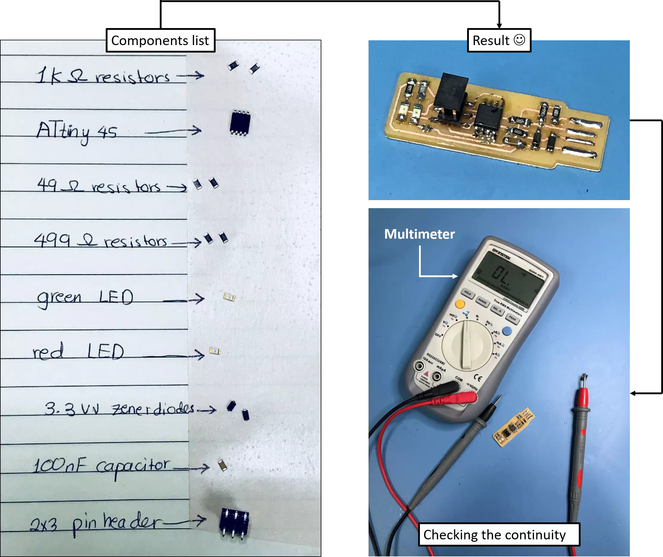
The board is ready for soldering the components. As shown in the figures below I used tape to stick and list the components because of their tiny size. Then I used iron soldering technique. Finally, I used millimeter t check my circuit connections to know if there is no short circuit or any a place that needs to solder well. The milling was first for traces then I repeated the same setting steps for the outline cut. The following figures summarize the next steps
Programming the board
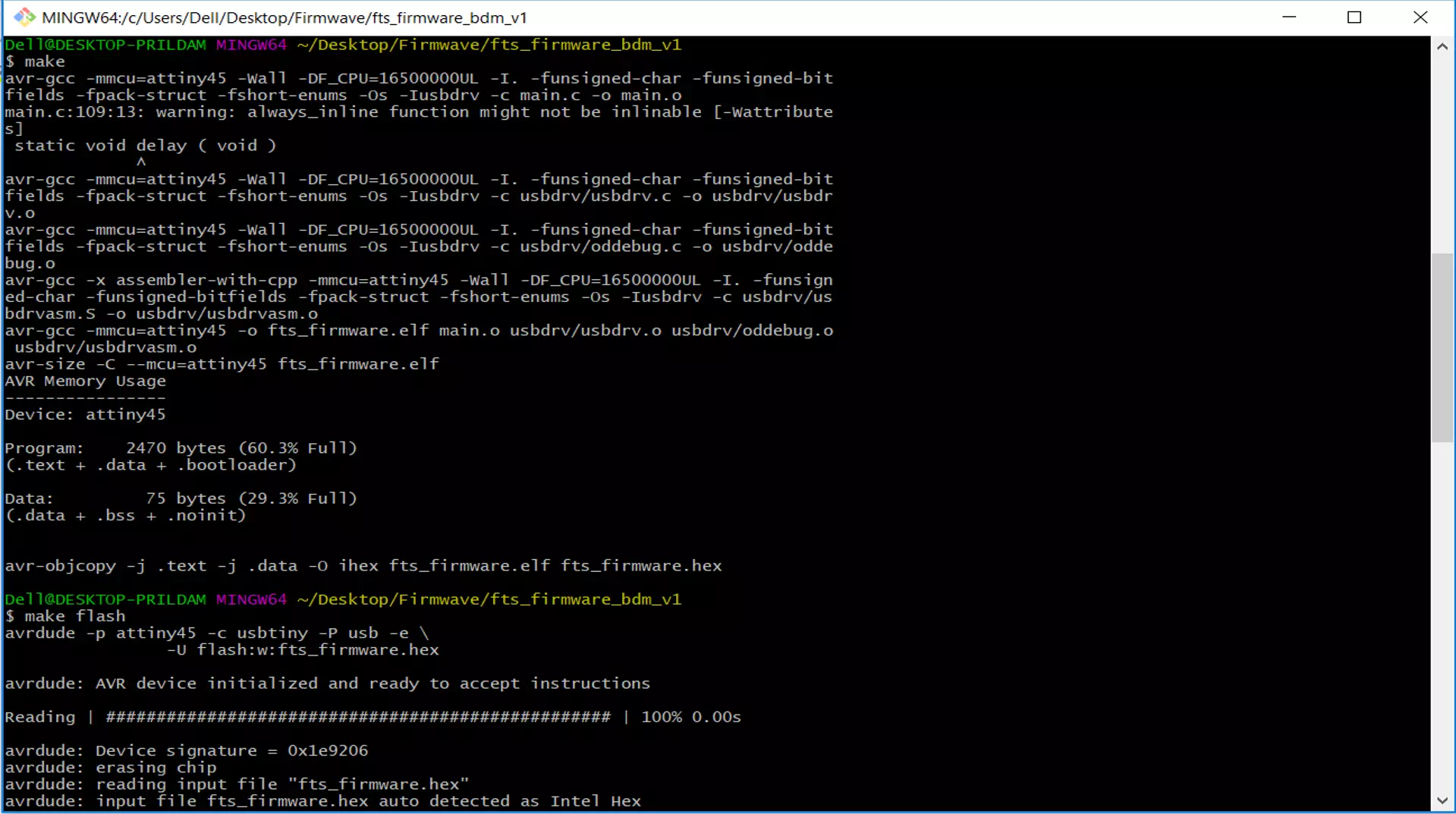
Now the fabricated board is ready for programming. I followed the steps in the tutorial to make my board works as a programmer. I downloaded the firmware source code. Then I open it with git bash. After that, I run it by typing make as shown in the figure below: This will result in outputting the hex file as shown in the below figure:
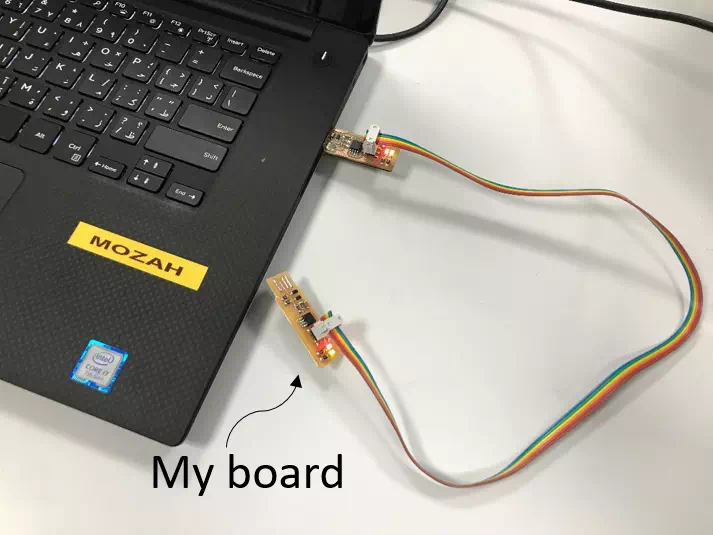
Then I used an alternative programmer to program my FabISP board by using the connection below:
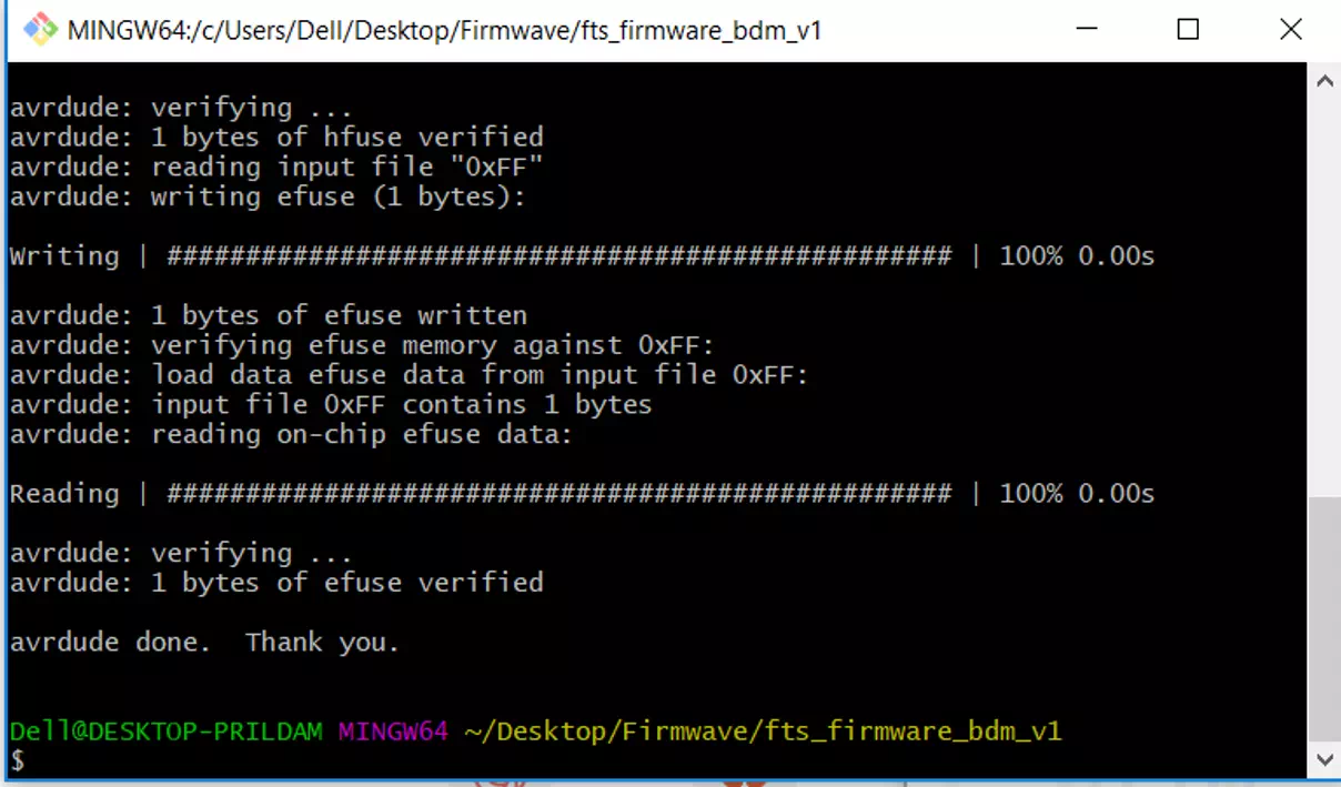
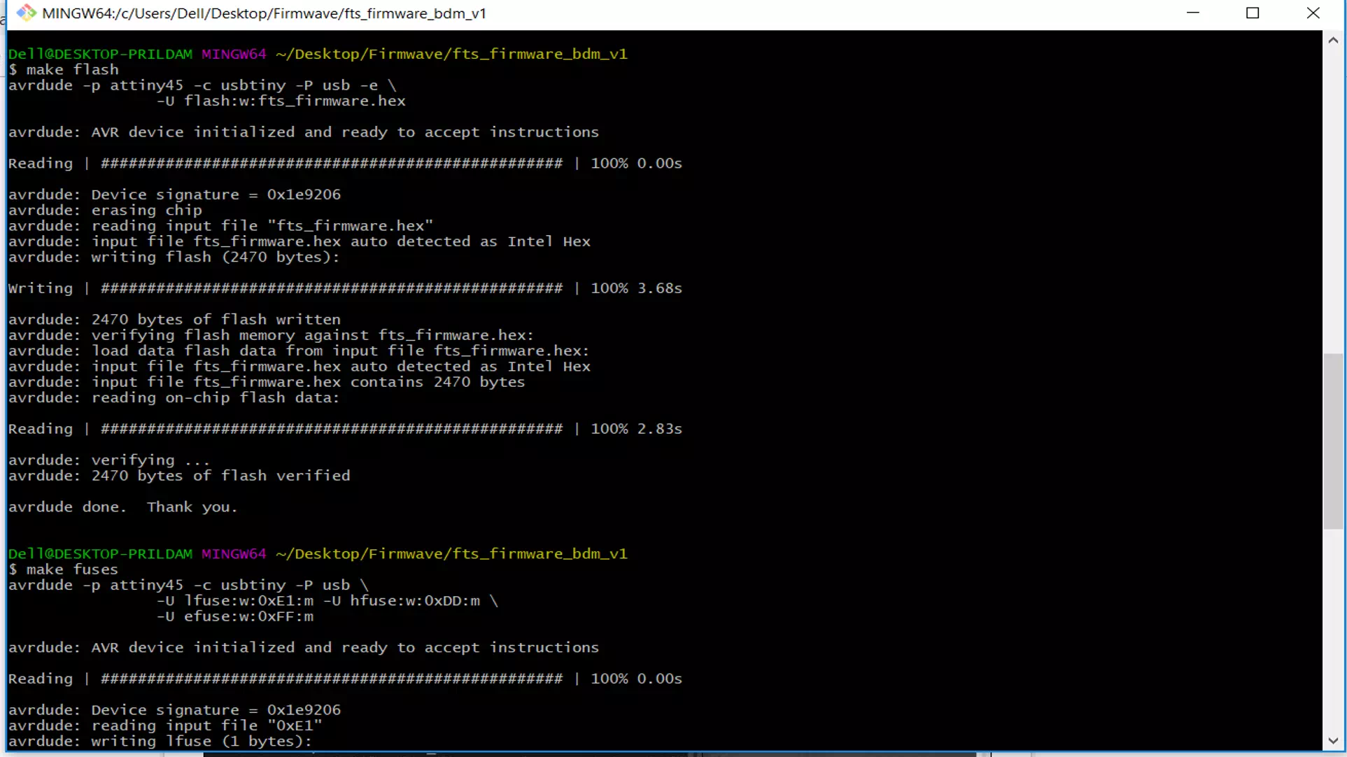
Next, in firmave software, I open it with git bash and I run: make flash, make fuses and they verified successfully. As shown in the figure below:
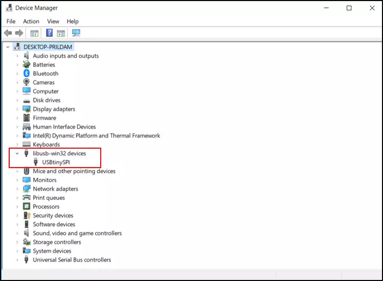
Finally, my board should be a programmer now! I disconnect the previous connection and I connect my programmer to check if its work. As shown in the figure below it appear in the device manager.
Congratulation for me :) ... Now my board became a programmer the last step to do is: make rstdisbl as shown in the figure below: