Task required:
We assigned to make a networking communication between two boards.
What I did?
I chose to make wire communication between two boards. One board I already made in input devices week and the other one had been made in this week containing display pins that I would like to use for showing a text. Note, this display will be beneficial for my final project to present the temperature sensor reading.
Procedure
Display’s code and connection
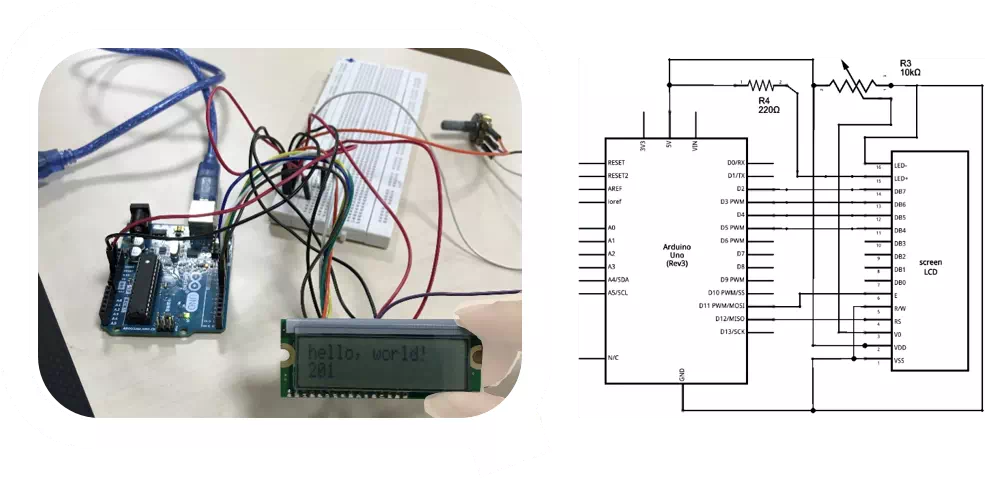
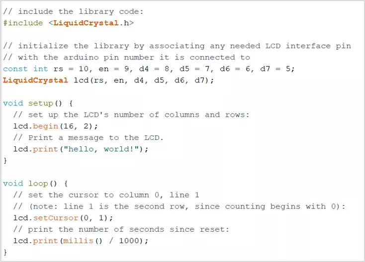
First of all, reviewing the guide , the display connected with Arduino Uno. Then a code presenting the text ‘Hello World’ presented on the screen.
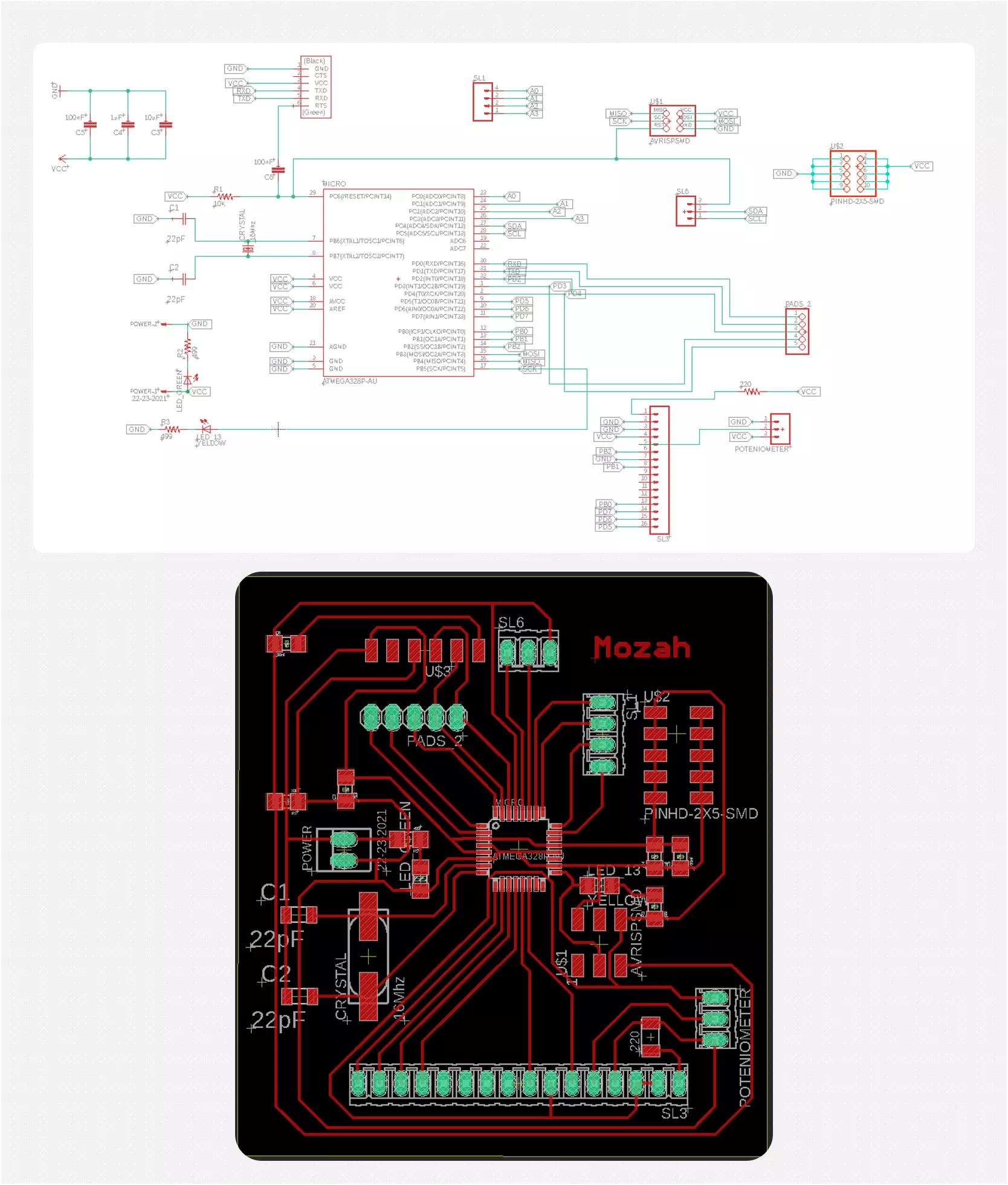
Next, after testing the display and knowing the pinout. A new board was made containing the display pins. The same design for the board made in input devices week had been modified and the new pins were added. The new design does not have pins for the motor or thermistor’s resistance. However, it has pins for a potentiometer to control the display’s lighting. Therefore, a resistor of 220 Ohms was added to the display pins as well. Following screenshots show the board’s schematic diagram and layout which are made in Eagle.
The following figures show some screenshots of the fabrication process:
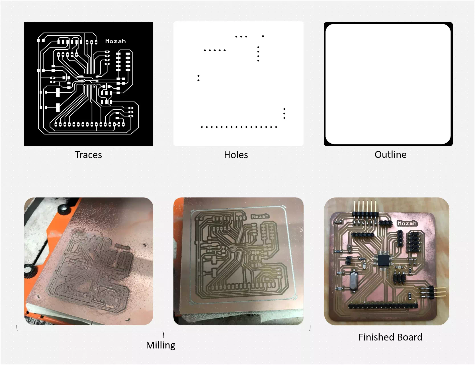
An important note to be mentioned that a resistor of 220 Ohms was not available. To solve this problem, two resistors were soldered on top of each other to make a parallel connection and drop the total value and reach about 220 Ohms. The figure below presents this task.

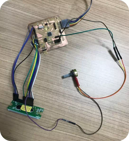
The board was programmed successfully. Then, the display code “Hello World” was uploaded to the board as shown in the video below.
Wire communication
Now, the main task is making the communication between the two boards. Before starting the task I went to search and get information about this topic. I read many resources and one of them is the guide
What is communication protocol - I2C ?
Inter-Integrated communication protocol is a serial communication protocol intended to allow communication between multiple slave nodes with one or more master nodes through two wires of SCL and SDA.
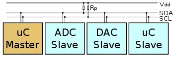
Master/slave is a model for a communication protocol in which one device or process (known as the master) controls one or more other devices or processes (known as slaves). Once the master/slave relationship is established, the direction of control is always from the master to the slave(s). In my assignment the old board is the slave and the new one which connected with the display is the master.
I2C Interface
I2C uses only two wires: SCL (serial clock) and SDA (serial data). Both need to be pulled up with a resistor to +Vdd. There are also I2C level shifters which can be used to connect to two I2C buses with different voltages.
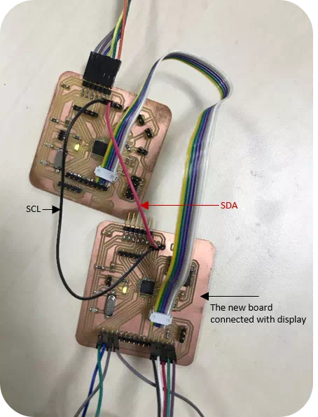
Before running my own code I did some tests shown below as my first time dealing with networking communication. I used an example in Arduino to be familiar with slave and master codes.
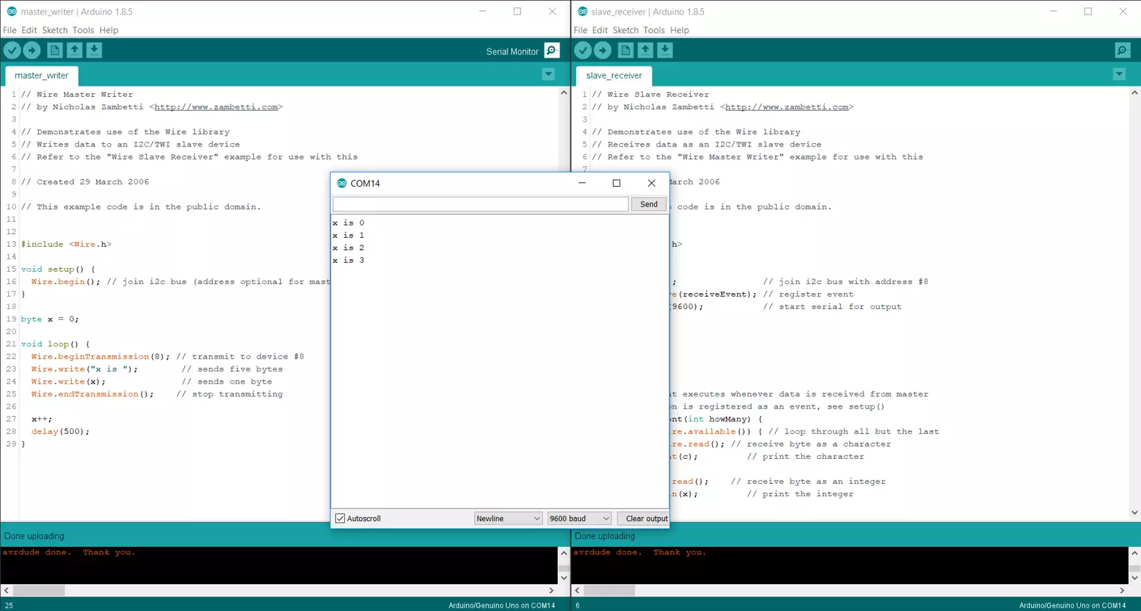
After that, I modified them and I merged the code of the Hello world to run the display using wire communication. First the Master code, it includes the hello world code.

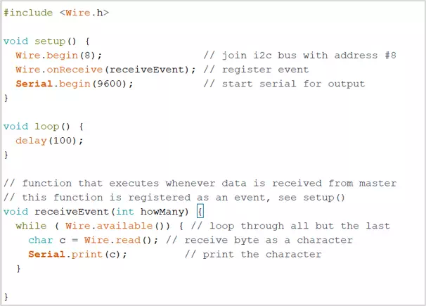
Second, the slave code which receive the text and send in to the PC.
