What I learned:
What an amazing topic! I learned about 3D printing knows also as additive manufacturing which widens in today’s modern world. It’s a layer-upon-layer technique used to synthesize a three-dimensional object. The process includes successive forming of material layers under computer control. 3D printer machines allow producing complex shapes easily as well as components that cannot be done by laser cutting or milling machines.
Task required:
We assigned to design and print 3D model that is difficult to produce by laser cutting or milling machines. Also, scan an object. Moreover, test a 3D printer calibration as a group assignment.
what I did ?
- Download free design to Test 3D printer calibration [Ultimake extended 3] as a group assignment
- Design and 3D printing ball bearing using CATIA. Then use Cura software to set the object printing options like size, density, quality and time.
- Scan fablab mug.
My procedure:
3D printng
As my favorite task is 3D modeling I decided to design a ball bearing to use it as key-ring. The ball bearing is a type of rolling elements that use in mechanisms structure to reduce rotational friction and support radial and axial loads. Ball bearing contains three main parts balls, inner race, and outer race.
1. CAD design
I would like to use CATIA software for designing my object as it’s my favorite software for 3D geometric. CATIA - stands for Computer Aided Three dimensional Interactive Application. It is the most powerful and widely used CAD (computer-aided design) software of its kind in the world. Actually, I used this software during my undergraduate studies as we assigned to prepare 3D models for some of the term projects.
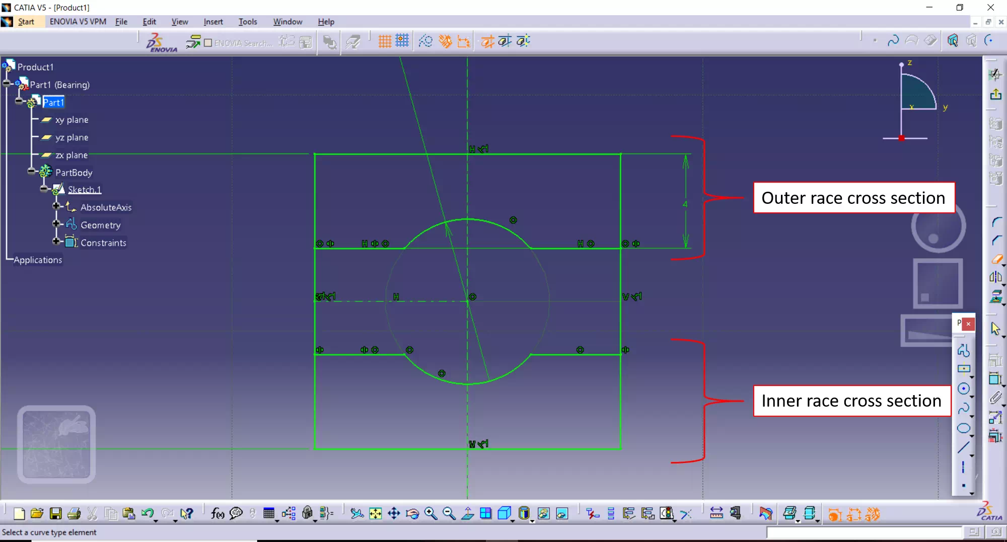
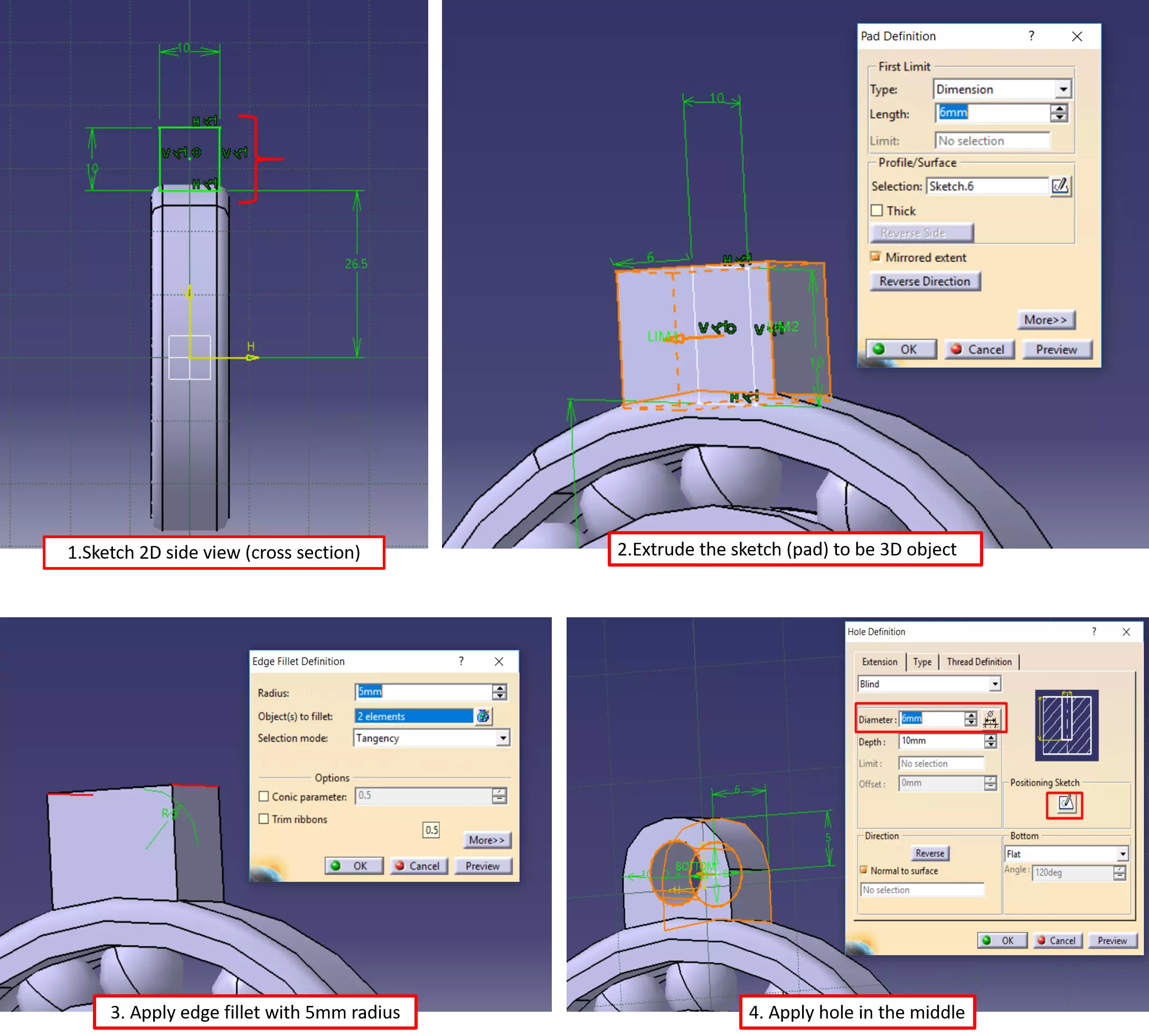
Well, let’s begin with sketching a cross-section for the bearing races. As shown in the figure below I sketched a cross section in yz axis.
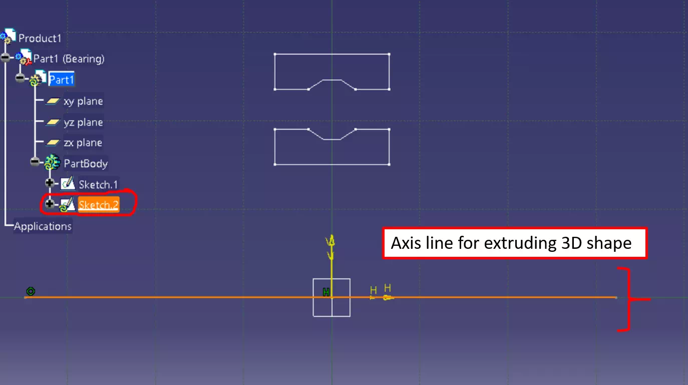
Then I exited the sketch to extrude it as a 3D object. I start a new sketch on yz axis by double click on it then I draw a line to be a rotation axis as shown in the figure below:
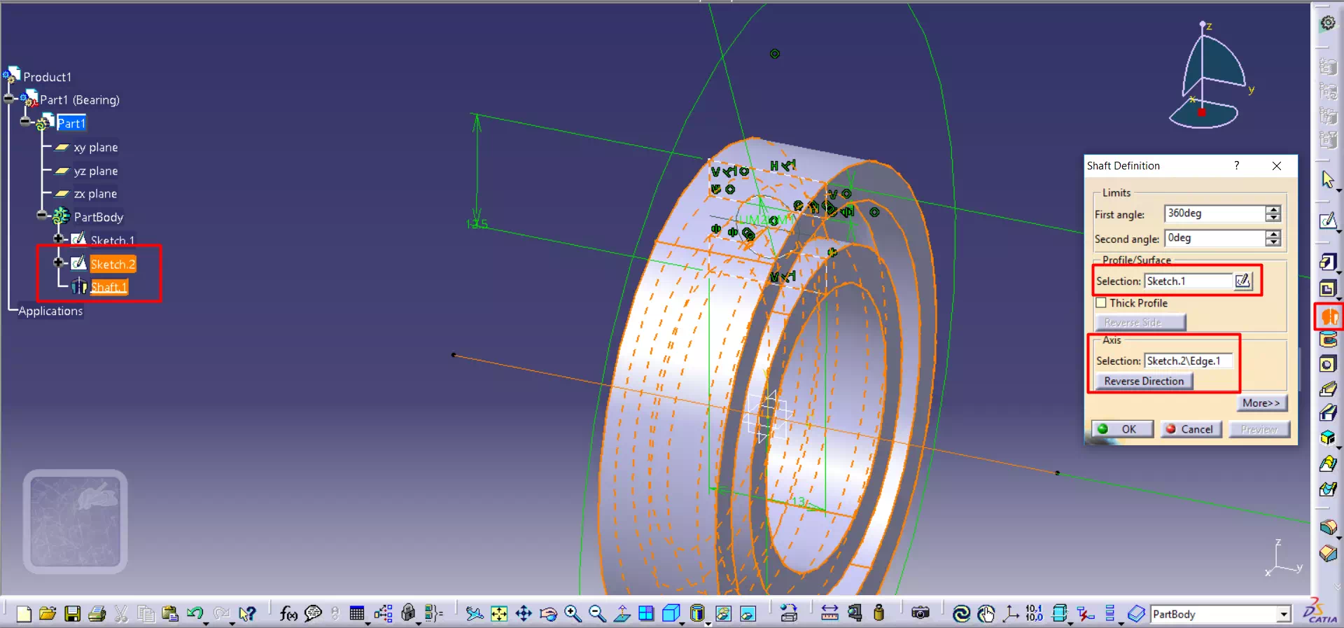
Then, I exit the sketch and used shaft command. Therefore, the figure presents a view of the outer and inner races.
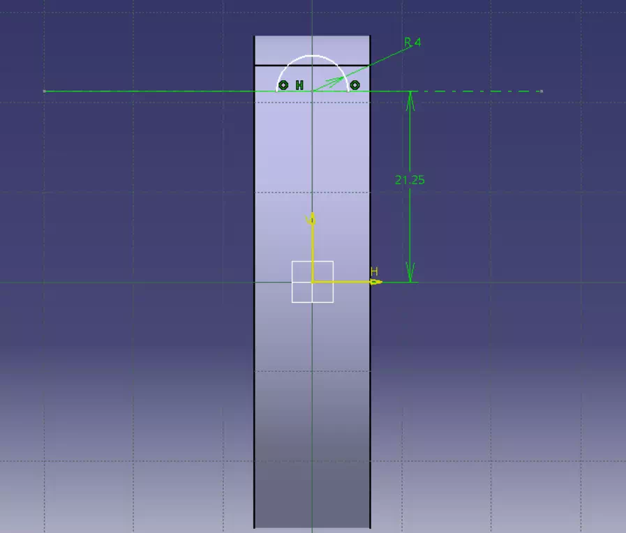
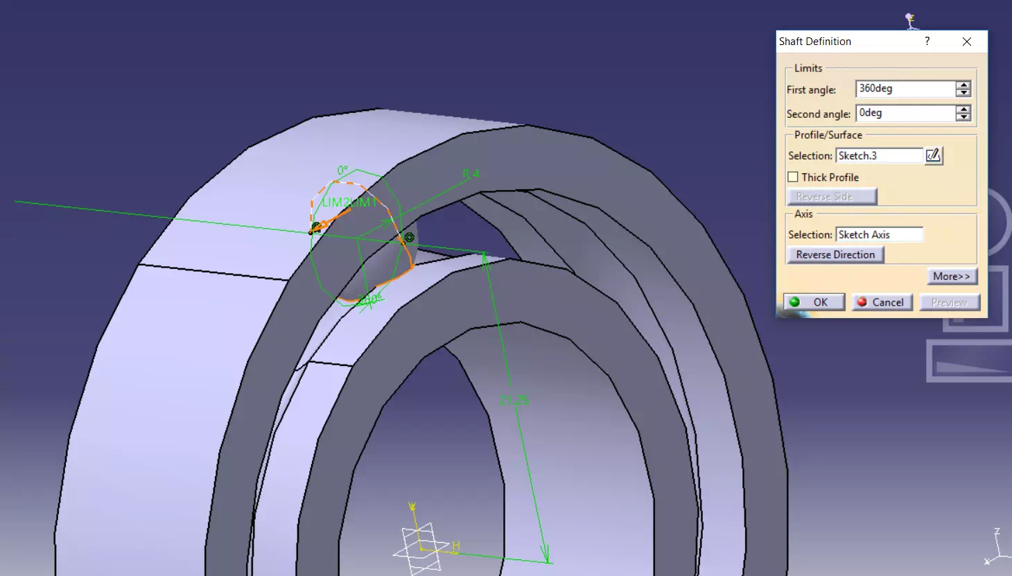
Now, the remaining steps are making the balls. I specify a mid-line between the outer and inner diameters as the center for the ball and I draw an arc (half-circle). Therefore, I used shaft command to extrude it as sphere as shown in the figure below:
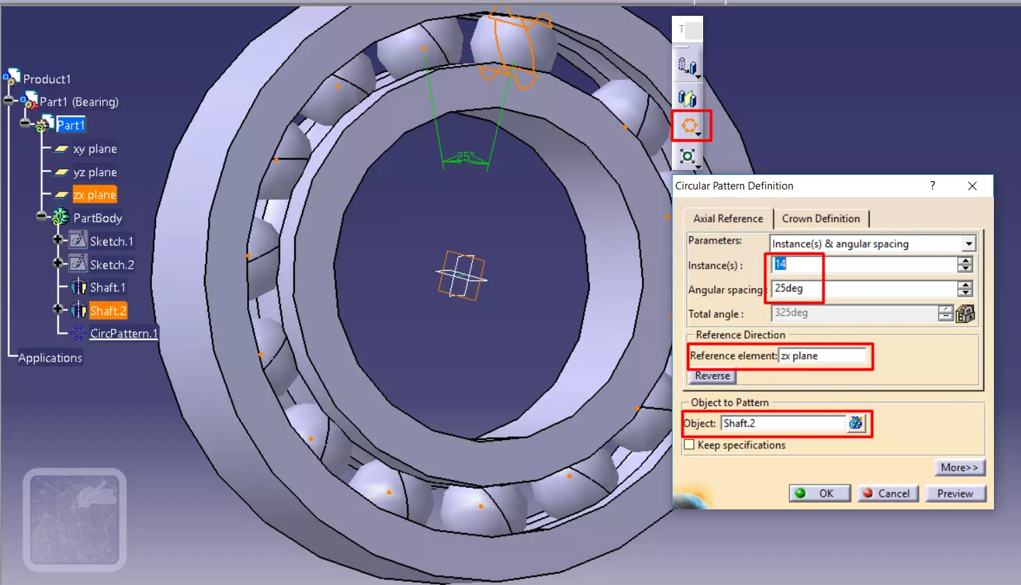
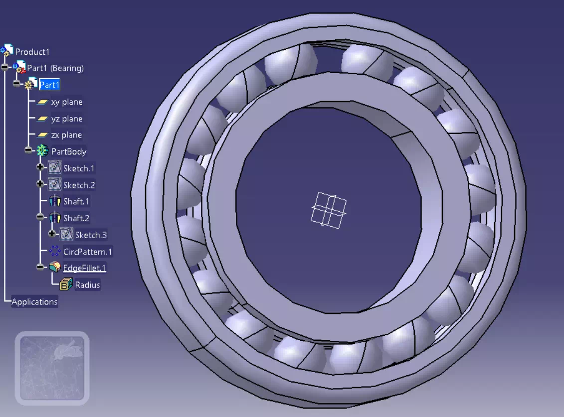
After making one ball I used circular pattern command for double the number of balls. As well as, I used Filled edge command with radius 2mm. The figures below present the two steps;
Adequately, the bearing structure is ready and to make it as key-ring I added few steps to design chain design. The figures below summarize what I did;
2. Cura software and printing result
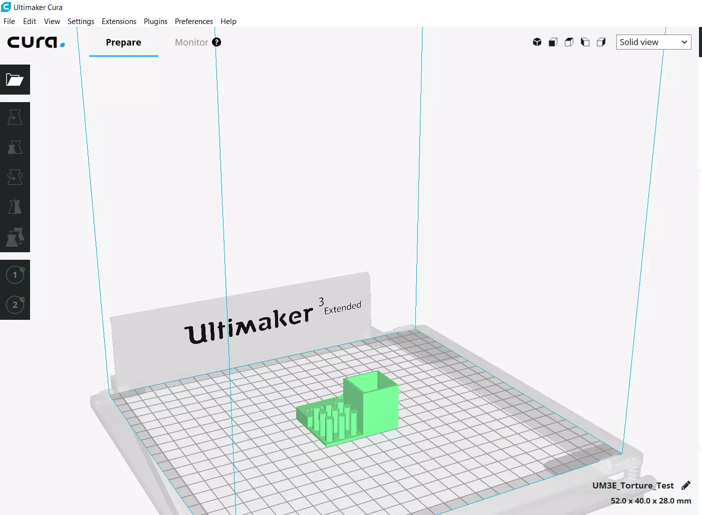
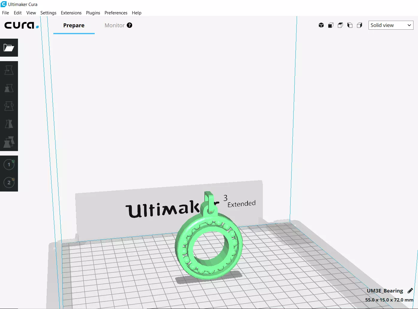
An existed software I used to prepare my setting before star printing is Cura. It’s free and involves multiple options to control the product situation and quality. Before printing my object I downloaded a torture test to test the printer calibration as a group assignment. Furthermore, because 3d printing is additive manufacturing I expect to get objects longer than the length in the design. Also, a smaller hole than what I designed. The figures below present the object in the Cura screen as well as the setting that I used to print. Notice that I chose Ultimaker extended 3 to print my first test. Moreover, the format to open the files in Cura is STL but to print it we should save the file as G code since the printer understand G code language.
Cura setting
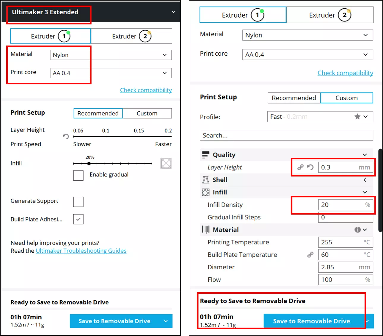
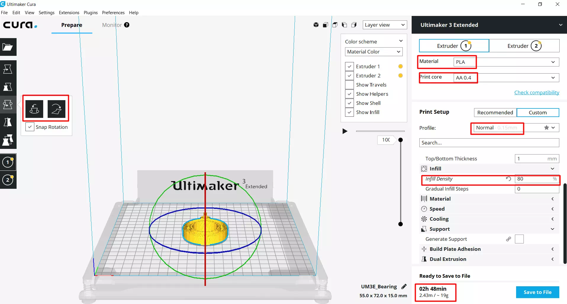
As shown in the figure below there are two extruders for this printer so I selected extruder1 which contains the filament. Then the material is Nylon as it’s my chose to try with this available one. Then the print core is 0.4 which is the printer nozzle size. Next, the layer height as the thickness of this layer becomes small as the number of layers will increase. As a result, the time will increase and the surface will be smooth more. Next is, infill density as the number increase you will consume more material.
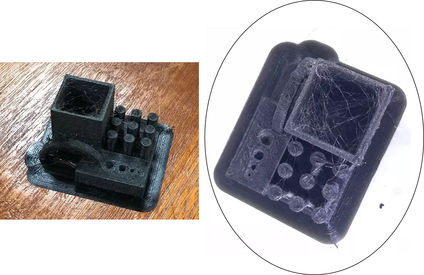
The result was not accurate. The speed was high compared with the component size. Also, I discovered that one of the machine axis was vibrating which influence on the angle of loading the material. Therefore, the size of the holes was approximately the same due to inaccurate result a well as it was hard to measure the sizes of the angles.
Generally, I got an idea about choosing a proper setting. To start printing my design, I saved the file in CATIA as STL. Therefore, I opened in Cura as shown in the figure below:
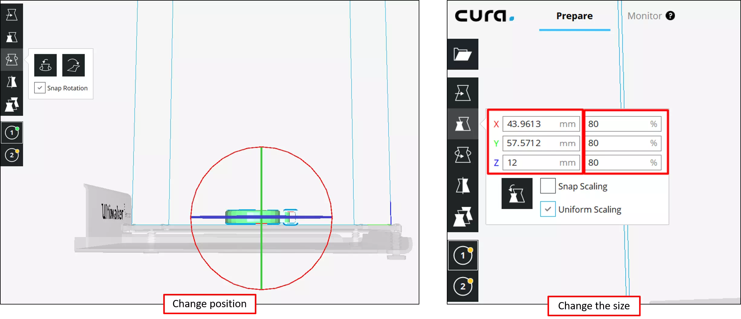
Therefore, I changed its position and scale as presented in the figures below:
3. Printer setting
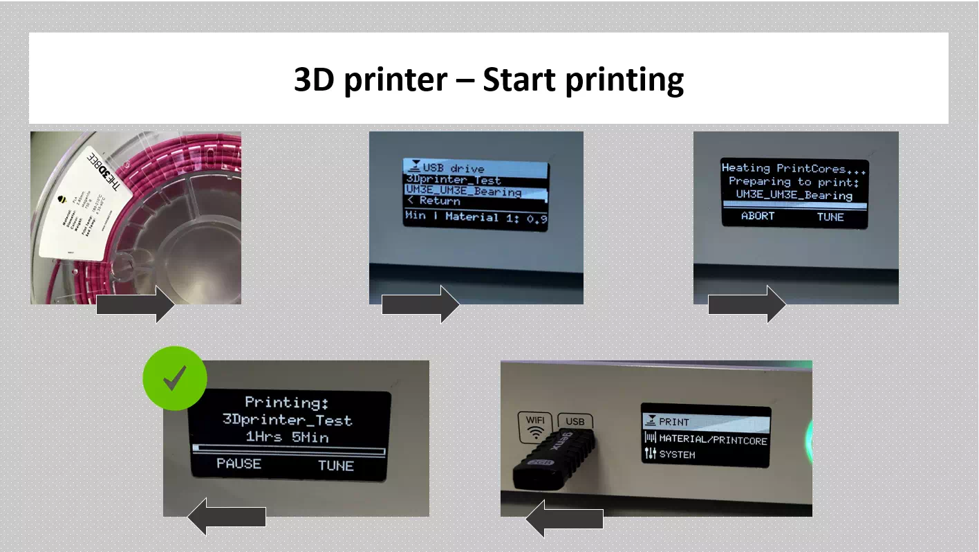
Important points I would like to mention are the steps of using after preparing the printing setting in Cura software. The file should be saved in G-code format. Then using USB drive install the file like the following:
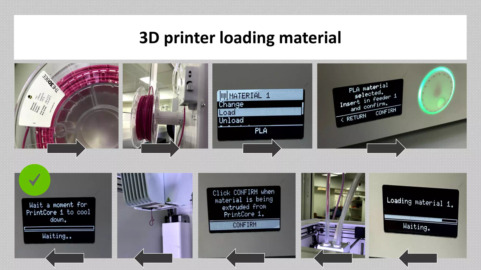
Material loading :
There are different types of material such as ALP and Nylon which I used in printing my parts this week. Furthermore, each printer has a sufficient position to enter the material roller in the back of the printer. Then choose material in the printer screen and make sure that you enter the roller beginning then choose load material and wait for the heating process and extrude the filament. Note, as this printer has two nozzles so make sure to set either material one or two.
Start printing :
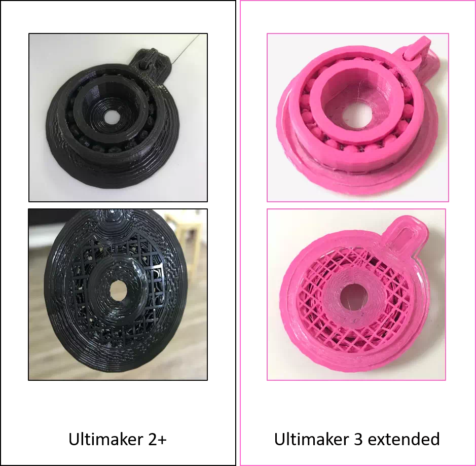
The result
Well, the result was not bad but also not as it should be. I print it in two printers Ultimake 2+ and extended 3. I think the design is very small and it was hard to remove the support material easily. The balls need a very thin tool to remove the supports.
Option1(Ultimake 2+) : The layer height 0.1mm, wall thickness 1mm, infill density 80% as well as support brim 5mm.
Option2 (Ultilmaker 3 extended): The layer height 0.08mm, wall thickness 3mm, infill density 80% as well as support brim 7mm.
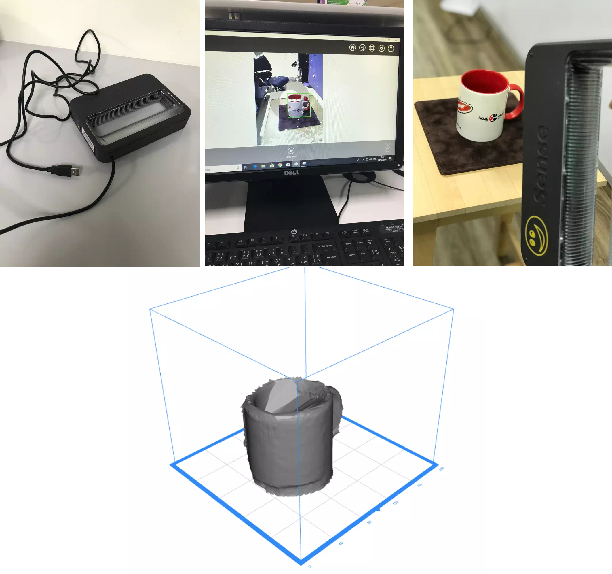
Scanning
I used Sense 3D scanner to scan a mug. It was my first time to scan an object! I tried many times but the results were less than what I expect. Generally speaking, it was a fun task but I think it couldn’t give an effective result.