Task required:
This week we assigned to add a sensor to a microcontroller board and do some measurements.
what I did ?
I decided to begin with a sensor that is related to my final project. Therefore, I chose to use temperature sensor. Firstly, I used 3D printer sensor to test it by Arduino UNO. I tried understand the circuit connections and alternative code to start with. Unfortunately, the result was dissatisfied because the reading data were vibrating between negative and positive region. Secondly, I used another available sensor (100K thermistor) in the lab and it gave accepted reading which prove that the previous sensor was damage. However, I discovered that this thermistor is not suitable for my final project because it has a capability to measure maximum 100C temperature which is less than PLA heating temperature. Thirdly, I borrowed Daniele sensor which is similar to my project requirements (3D printer sensor) and the results was satisfied. Finally, I started to design my board in eagle. Then, fabricate it and programmed it. Therefore, to make my board useful for the final project I started with inspiration from satshakit board . Actually, I took the origin eagle file for satshakit and modify it depending on my final project requirements.
Procedure
Testing temperature sensor by Arduino UNO
The following figures show my connection and code used to test the temperature sensor.
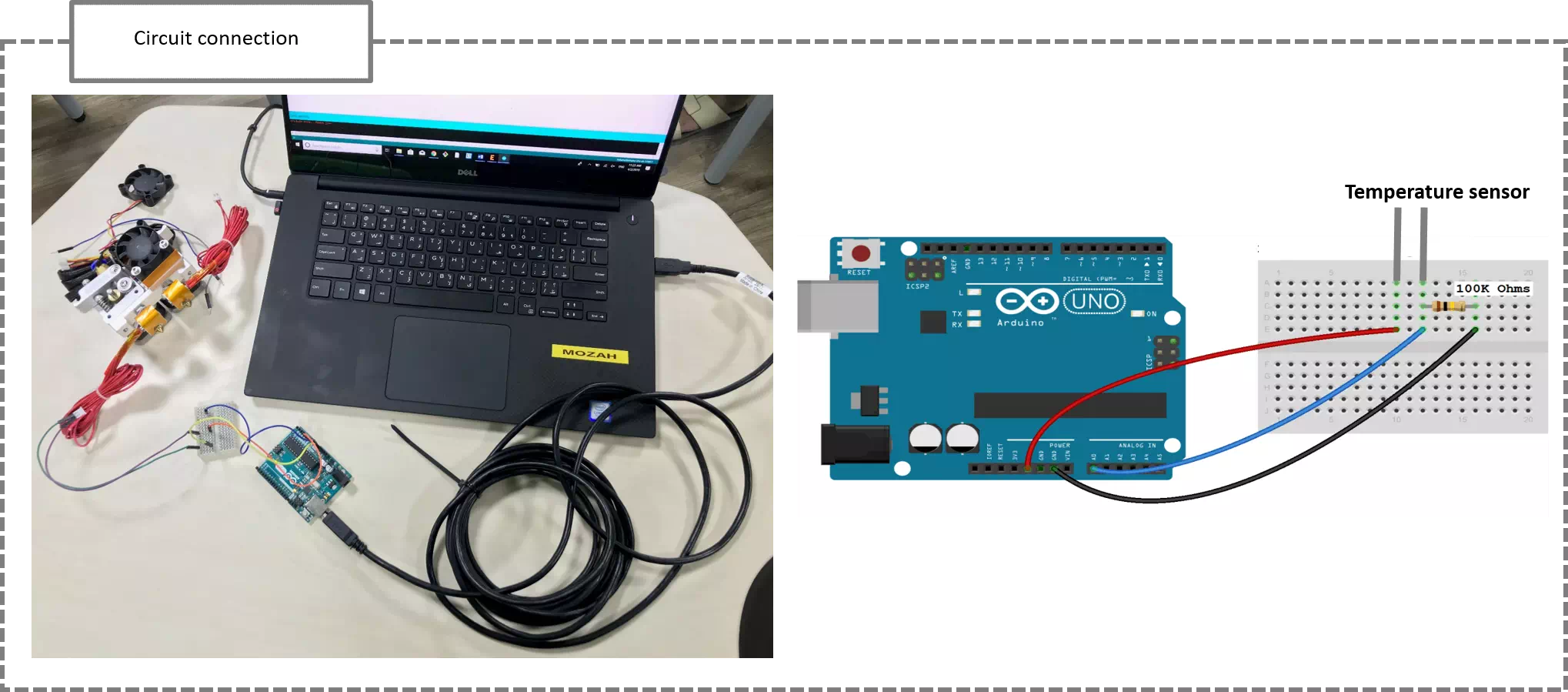
The temperature sensor is connected with VCC and analog pin in the Arduino. A resistor of 100K was required according to the used thermistor. On other words, the value of the resistor should be roughly equal to the resistance of the thermistor. In this case, the resistance of my thermistor is 100K Ohms, so my resistor is also 100K Ohms. The resistor is connected between analog pin and ground.
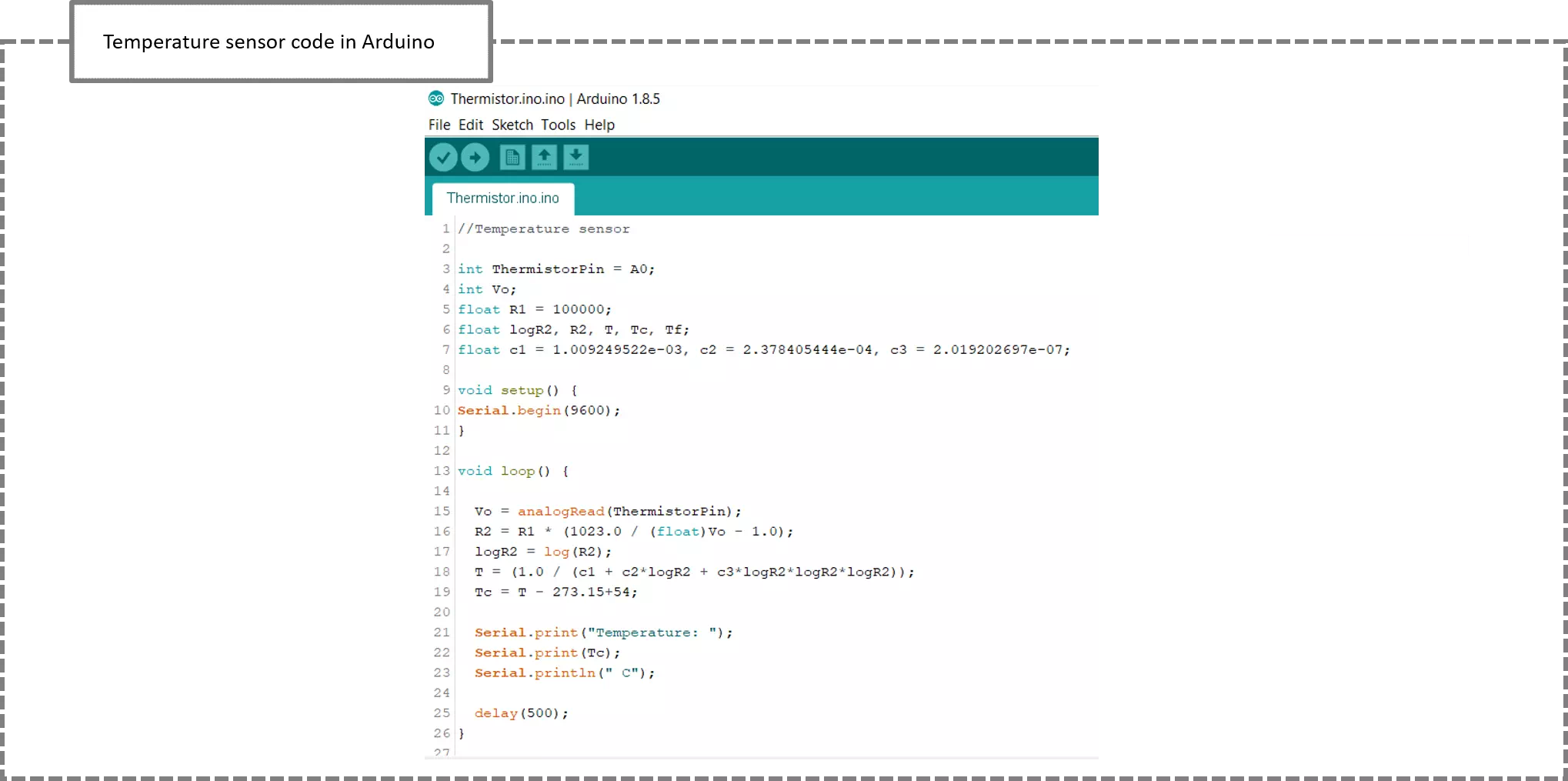
The Arduino will measure the voltage at a point between the thermistor and a known resistor. Following the guide , the voltage reading is known as a voltage divider. The equation for a voltage divider is: :
V_out=V_in x (R2/(R1+R2))
In terms of the voltage divider in a thermistor circuit, the variables in the equation above are:
 V_out :  Voltage between thermistor and known resistor (100 K ohms)
 V_in: V_cc = 5V.
 R1: Known resistor value.
 R2:  Resistance of thermistor.
By simplifying the above equation, Resistance of thermistor can be defined. Finally, I using Steinhart-Hart equation, the resistance of the thermistor is converted to a temperature reading.
Note, a calibration test has been used to approach an acceptable result. Repeating the measurements different times ended with adding 54 to the temperature equation in order to get the room temperature value.
New board design in eagle
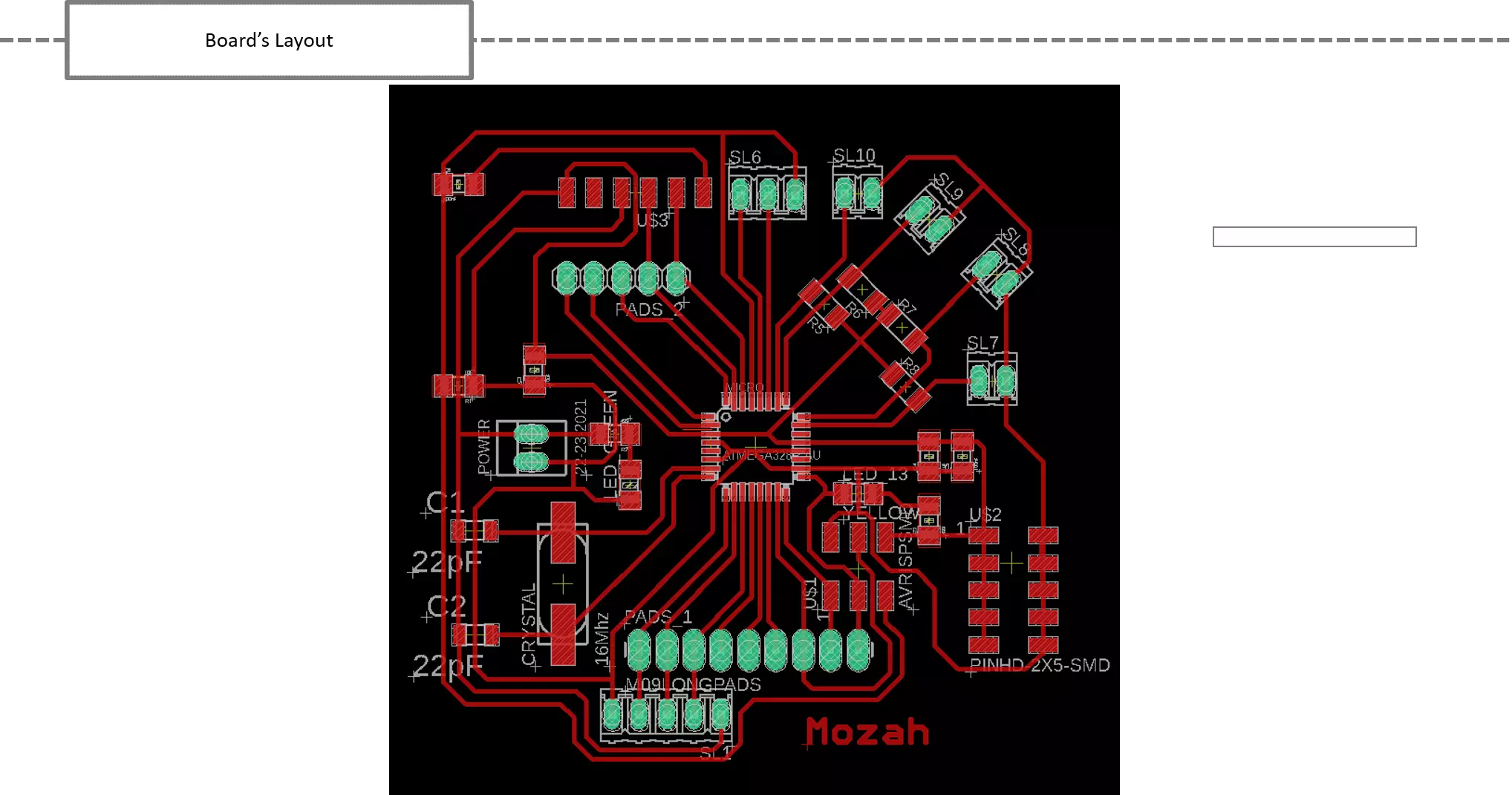
With referring to satshakit my board made as the following:
Note, I used the same steps in week7 to prepare the design.
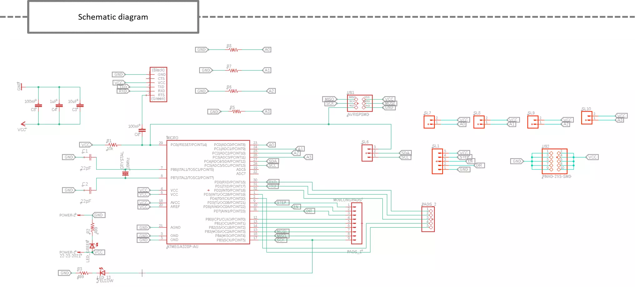
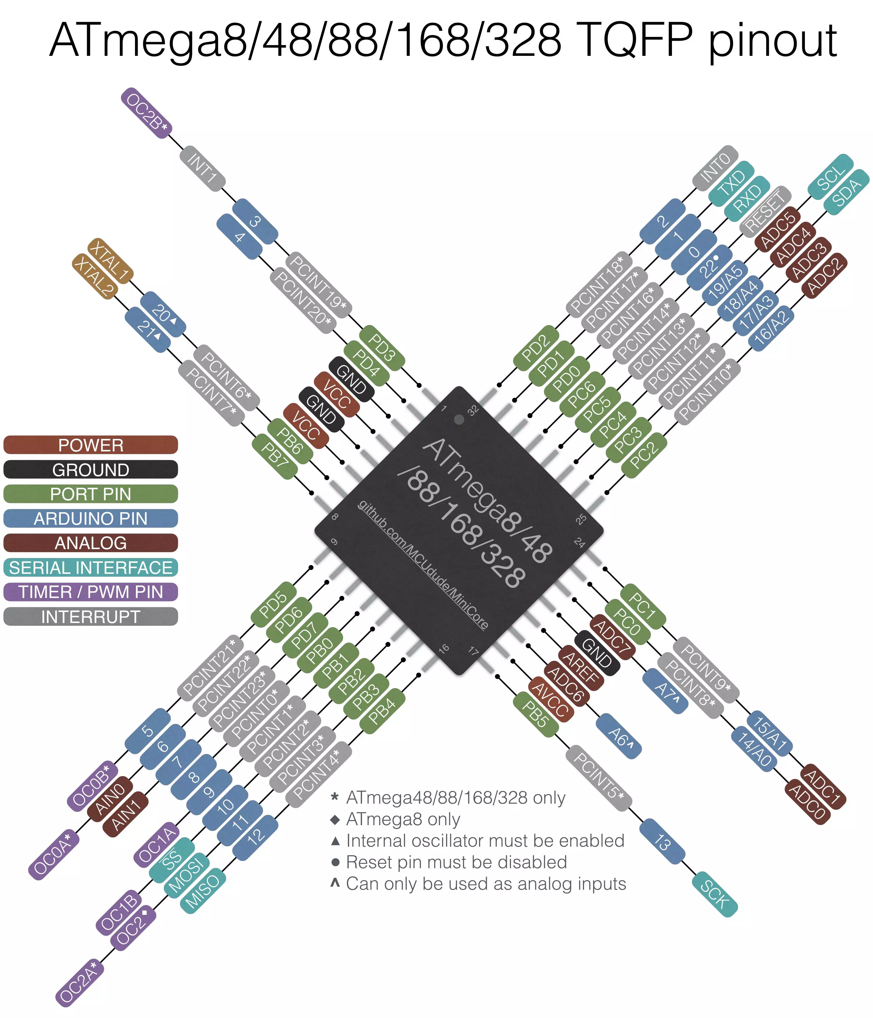
As shown in the schematic diagram, ATMega328 is used. It is a high-performance microcontroller. The figure below shows the pinout.
I deleted the components that I do not need. The modifications I made to the board are:
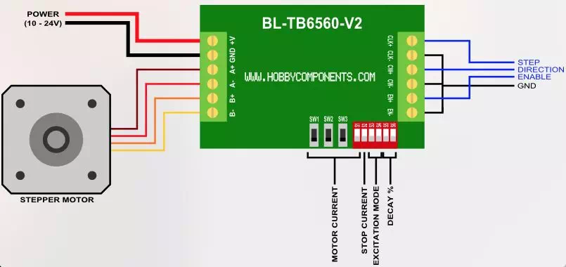
According to the final project a stepper motor pins are needed. The motor has four wires. They are A1, A2, B1 and B2. Those wires must be connected to a motor drive. Motor drives are used to run a motor. In other words, they are commonly used for motor interfacing. Motor drives are usually have only 2 input pins which take commands in form of digital high and low. One sets the direction of rotation and other is for step commands. Enable pin is used to control speed of a motor.Both the A+ and B+ wires are connected to A1 and B1 respectively. Likewise, A- and B- are connected to A2 and B2 respectively. The figure below presents the pinout figuration between a steppr motor and motor driver.
As mentioned before, the thermistor required an equivalent pull down resistor. Therefore, three extra resistors are added in case they may use in the future for more sensors.
Those connections are provided to connect the thermistor pins. In addition, the remaining three connectors are extra added in case they may use in the future.
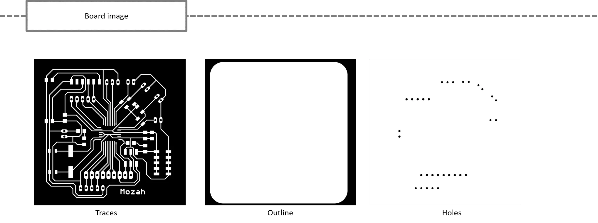
The board exported to GIMP for preparing traces, holes and outline images as shown below.
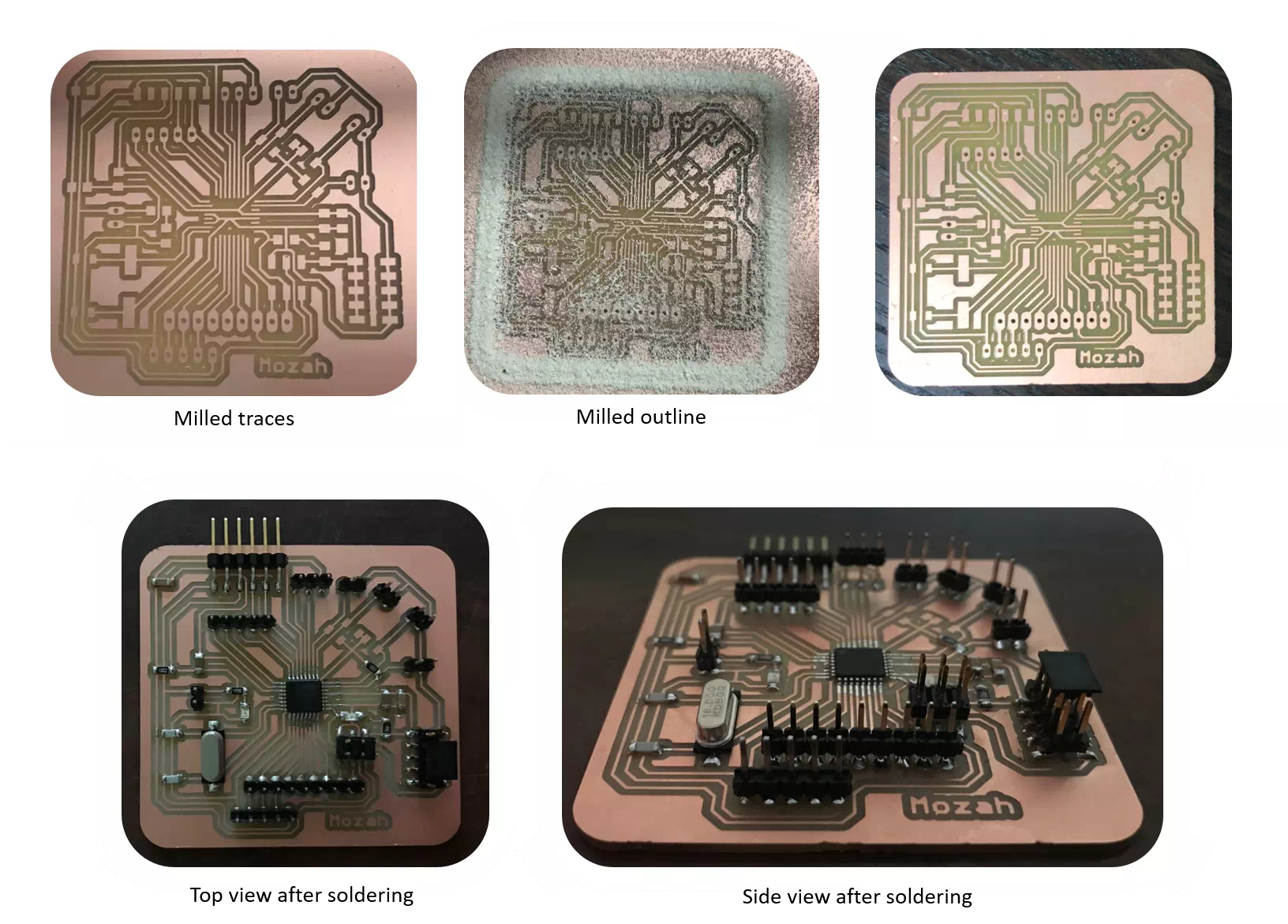
Fabrication process
Programming step
As shown in the video below my board programmed successfully .
Finally, I connected the temperature sensor with my new board and run the code to take some measurements. The video below summarize this step.