Task required:
We assigned to add an output device to microcontroller board.
what I did ?
The good thing for this week is that my board that was made input devices week is ready to run an output device .. Thanks for my great instructor Daniele who advise me and support me to produce a sufficient board. Furthermore, I chose to use stepper motor as output device for this week. After searching about motor’s connection. A code has been prepared to run the motor.
Motor’s connection
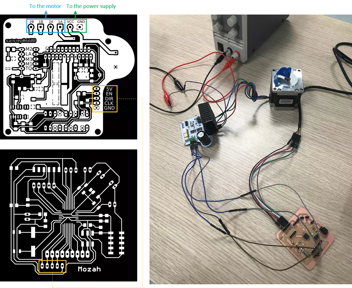
Starting from the motor wires. There are A1, A2, B1 and B2 wires. Those wires must be connected to a motor drive. Motor drives are used to run a motor. In other words, they are commonly used for motor’s interfacing.
An open source and fabbable stepper driver is used in this assignment. It is satstep6600 a low cost and fabbable stepper driver. Based on the PiBot TB6600 stepper driver.
Now, an important pins provided in the driver are as the following:
The figure below presents overall connection

Arduino’s code for running the stepper motor.
Once the hardware is hooked up correctly, the code below prepared to run the motor.
// Run a stepper motor
int x;
#define BAUD (9600)
void setup()
{
  Serial.begin(BAUD);
  pinMode(6,OUTPUT); // Enable
  pinMode(4,OUTPUT); // Dir
  pinMode(5,OUTPUT); // Step
  digitalWrite(6,LOW); // Set Enable low
}
void loop()
{
  digitalWrite(6,LOW); // Set Enable low
  digitalWrite(4,HIGH); // Set Dir high
  Serial.println("Loop 200 steps (1 rev)");
  for(x = 0; x < 2000; x++) // Loop 200 times
  {
    digitalWrite(5,HIGH); // Output high
    delay(5); // Wait
    digitalWrite(5,LOW); // Output low
    delay(5); // Wait
  }
  Serial.println("Pause");
  delay(1000); // pause one second
As shown in the code, setting the direction pin as HIGH would let the motor rotate to a certain direction otherwise it will reverse the direction in the case of LOW. Then, when enable set to LOW this means ENABLED. Finally, continually pulsing the CLK+ input will cause the motor to step in one direction.