
Lingyu Yue @ FAB LAB Szoil · 2019
© 2018 Lingyu Yue · Template by Bootstrapious

This work is licensed under a Creative Commons Attribution-NonCommercial-ShareAlike 4.0 International License.
Computer-Controlled Cutting
Assignments
Group assignment
Laser cutting :characterize your lasercutter, making lasercutter test part(s), making test part(s) that vary cutting settings and dimensions
Individual assignment
cut something on the vinylcutter design, lasercut, and document a parametric press-fit construction kit,accounting for the lasercutter kerf, which can be assembled in multiple ways
I found that I like laser cutting a lot, I can design something and make it straight away. Though to achive well function part is hard.
Laser Cutting
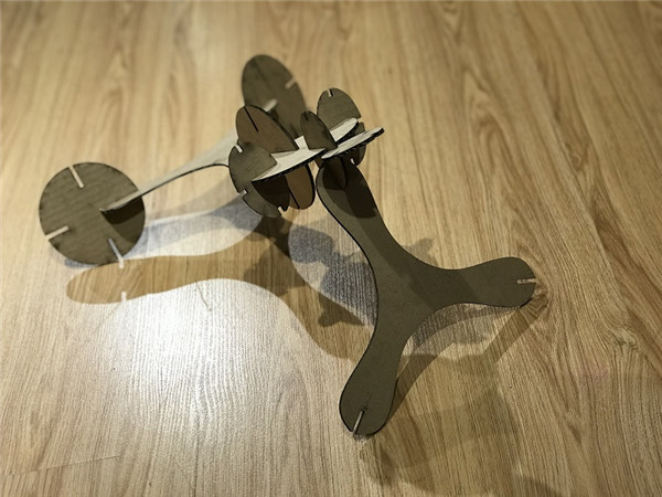
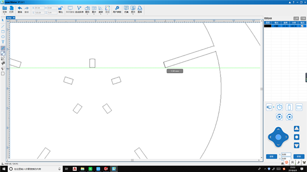
I wanted to make some blocks for the kids , hopefully it can both good in small size and big size. So I tested my idea with the Lasermaker software.
At first, I measured the cardboard with the vernier caliper .
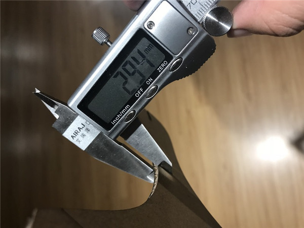
In order to cut and connect, I made the slit wider than 2.94mm and I make the longer slit as 3.10mm. Then I download the file to the laser cutter to cut.
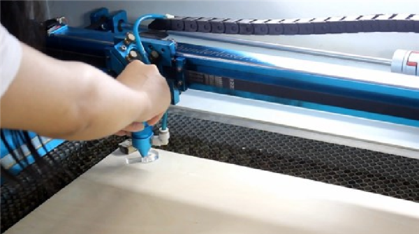
Before cutting , I set the laser cutter , adjust the laser focal distance, simulated the cutting process, and set the original point, click the
I tested the fit-in parts to see if the pieces is good to use.
The structure is good to use but the cutting edge is so burned that black my hands.
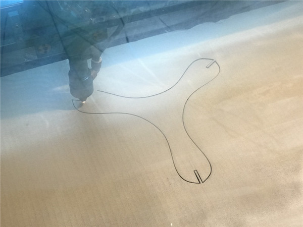
Then I wanna to cut something with the wooden board, I had a wireless transmission module, so I designed a light cube.
.jpg)
.jpg)
.jpg)
.jpg)
w4_lightcube_test from Lingyu Yue on Vimeo.
I didn't do the documentation work well this year, I left the record way back from my project work, so I wrote my ducuments just before the deadline. For my final project, I made a calendar and a canlendar base.
First, I designed the canlendar part. I like the flip calendar a lot.
Laser Cut Perpetual Flip Calendar I get my initial idea from this website to make a flip calendar.
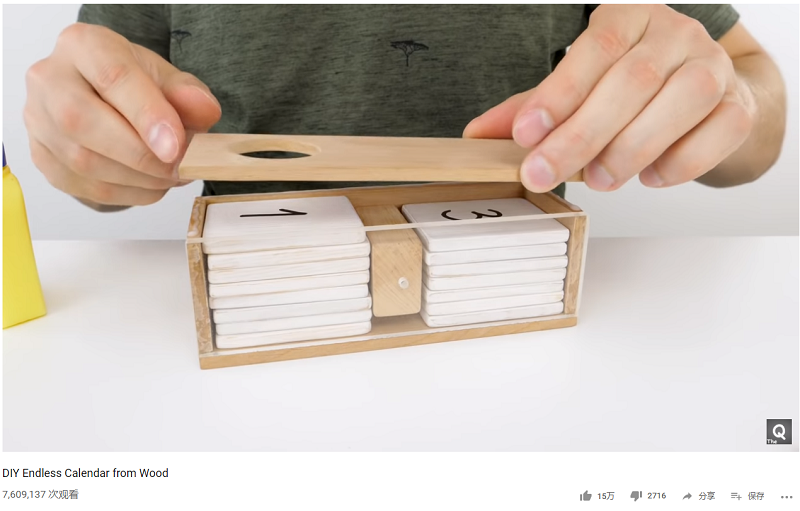
And I figure out how to design the flip part from this youtube video DIY Endless Calendar from Wood I knew that I could make several wood blocks with a part to divide them.
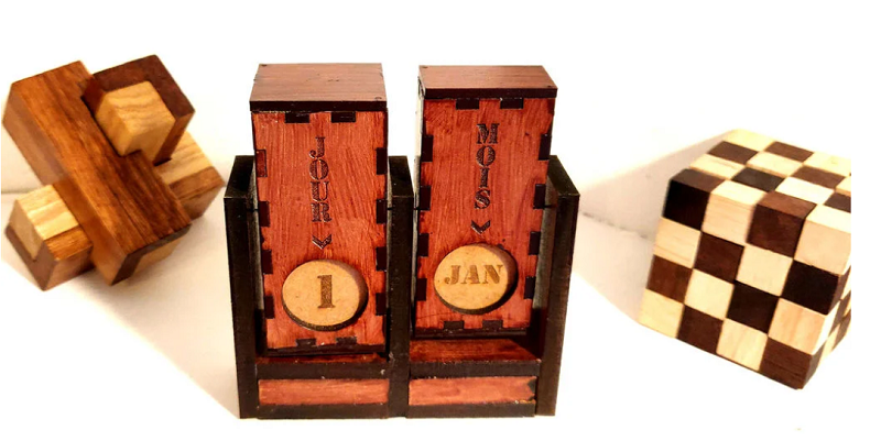
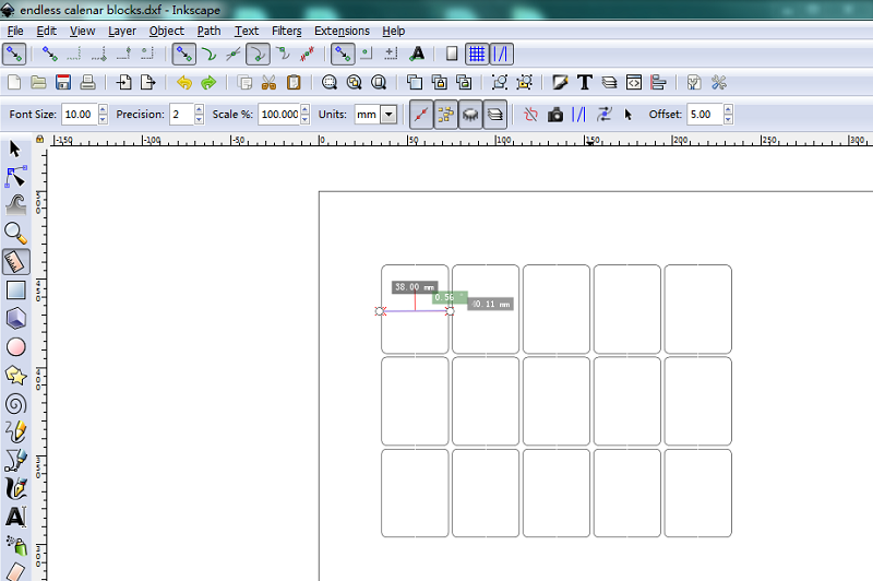
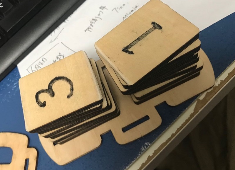
So I draw 15 wood blocks and test to cut, before assemble the calendar, I polish and wax the wood blocks.
Then I found a nice frame for the blocks, better than the cube one. It's the perpetual calendar from eureka kit. So I made a frame as below: Eureka Crate Review + Coupon – February 2019
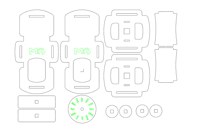
For the frame part, I tried several times, first time , I followed the eureka's design, use two parts in different directions to hold the vertical pieces. But I didn't realize that, the flip part can't go through the horizontal parts with the simple rectangle shapes.
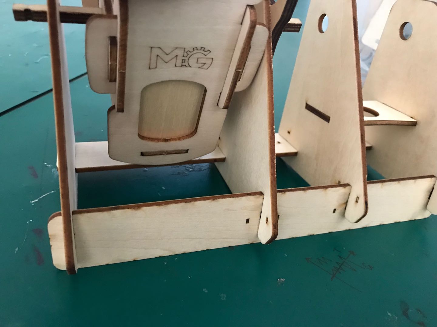
Then I redraw the frame with curves on the left, it worked.
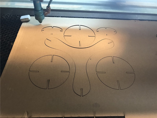
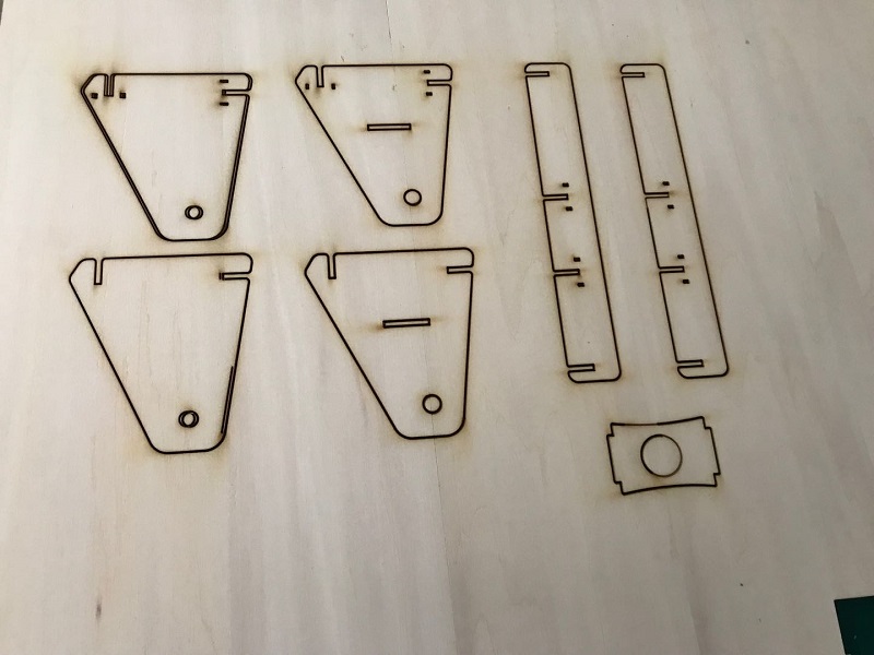
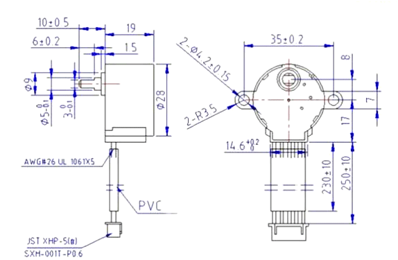
For the step motor part, at first, I measure the motor and roughly draw the outline. Then is came up to me that I could use the 28BYJ-48-dimensions to outline the sketch.
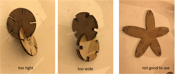
For connect the motor axle and the wood stick, I thought of making a 3D printing part ar first and I downloaded the step motor's axle connector 3D file. Then my coworker Yuanhan told me , we could simply design a laser cutter axle connector. So I draw 3 circles with holes which one of them fit the wood stick and one of them fit the motor axle, and I use two holes to connect them together.
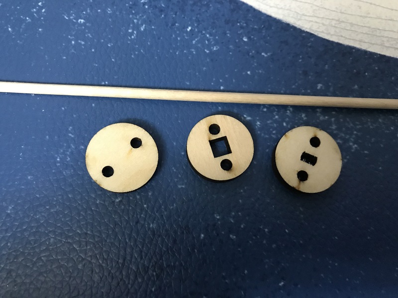
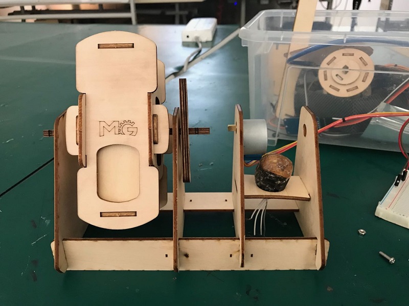
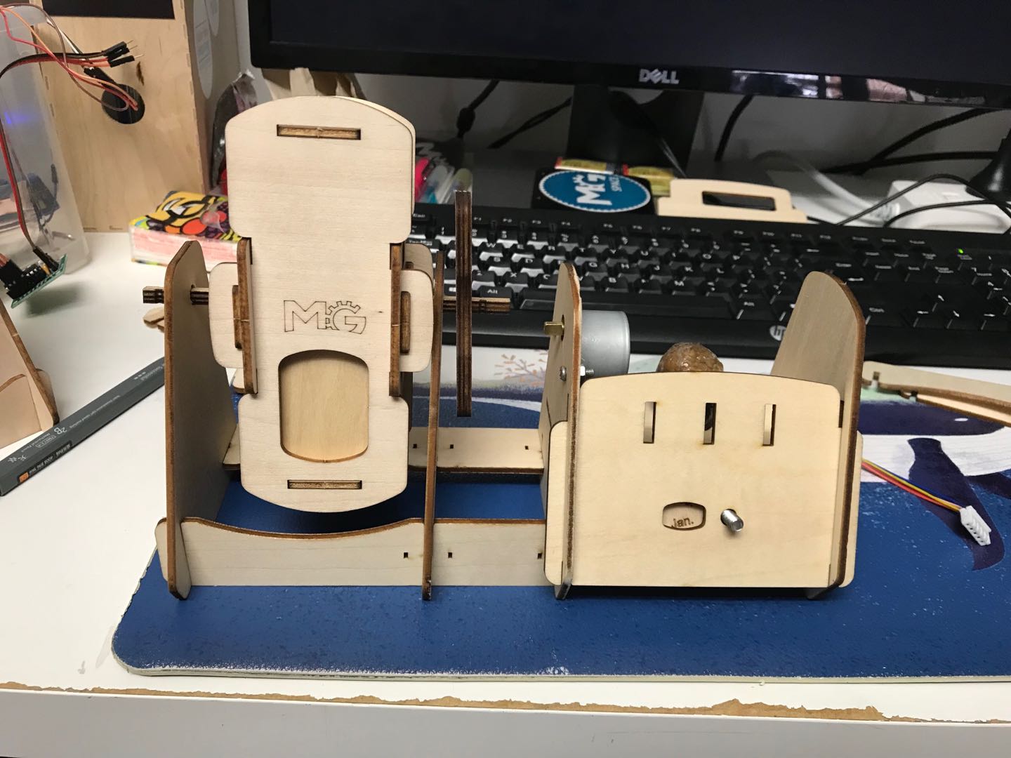
For the final assemble, I used two with wood stick holes and one with step motor axle hole.
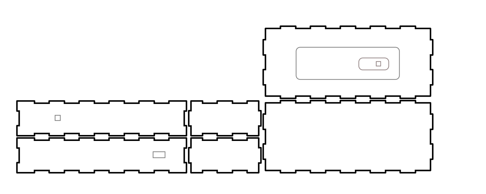
For the base to hold the elctronics part, I use Makercase website to design a box and then draw the port for my usb and button.
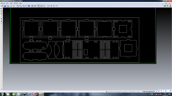
Now I finished my final design 2D part.
I drew some parts and cut them , but I didn't notice the measurement at first.So I failed a lot. And if you design something in inkscape and then save as dxf format, don't forget to choose the right measurement, mine is mm. If not, when it goes to laser cut, will be totally trouble.
Vinyl Cutting
There is a GCC I-craft vinyl cutter at MG .
For setting up the vinyl cutter, I:
- placed the cutting mat in the chosen direction and press the start rolling button
- inserted vinyl from the front side of the machine and placed its edge to the left side of the machine (zero)
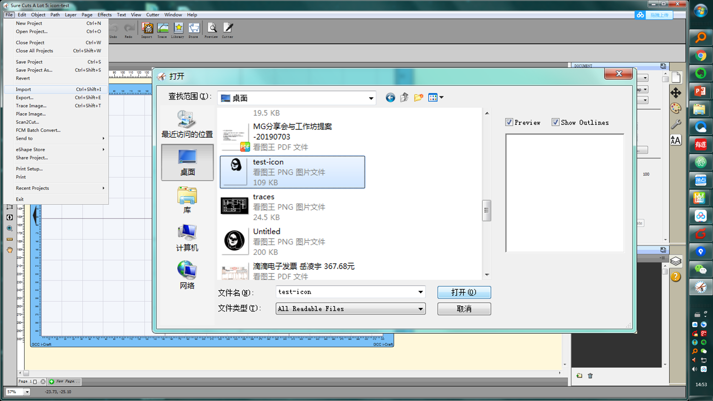
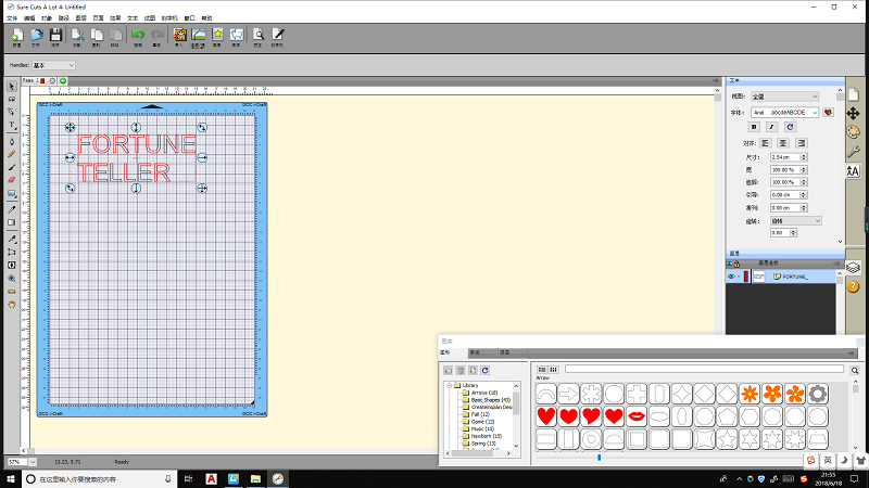
I used the Sure cut a lot to open the icon file I made in week 3.
For cutting the icon file, I:
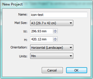
- set new project , set name/ mat size / orientation /units
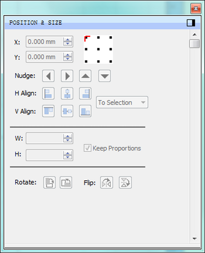
- set the zero point
- import the png file (this png file contais all vectors)
- cut settings, set the preset / holder /blade offset / pressure / speed
The picture documentation is as below :
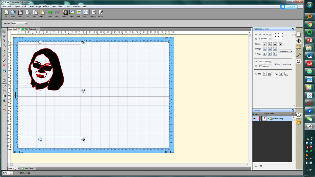
The blade will cut the red lines later .
Then I've got the cut done.
I tried to cut my inno logo also. But I found that there are too many filaments of my inno logo design file,I couldn't take it off from the cutter mat.
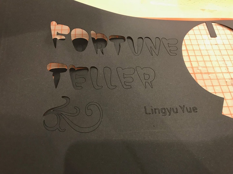
Then I tried to cut some letters , it ended up well.
For parametric press-fit design , I want to design a box, cause I could use box-shape pattern for many times. This video Fusion360: Automatically sized finger-joints helps me a lot.
First, I need to set paremeters.
- modify - parameters
- length -expression - (type the value)
- width -expression - (type the value)
- height -expression - (type the value)
- thickness -expression - (type the value)
- Ifingers -expression - (type the value)
- wfingers -expression - (type the value)
- hfingers -expression - (type the value)
- lfingerw -expression-use the formula : length/((lfingers*2)+1)
- wfingerw -expression - use the formula : widtn/((wfingers*2)+1)
- hfingerw - expression - use the formula : height /((hfingers*2)+1)
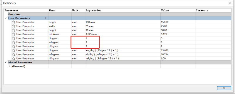
Remeber that the lfingers/wfings/hfingers unit, we should type none.
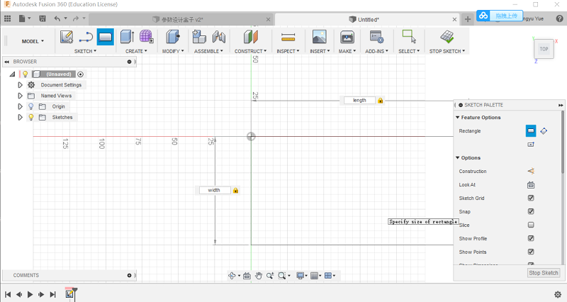
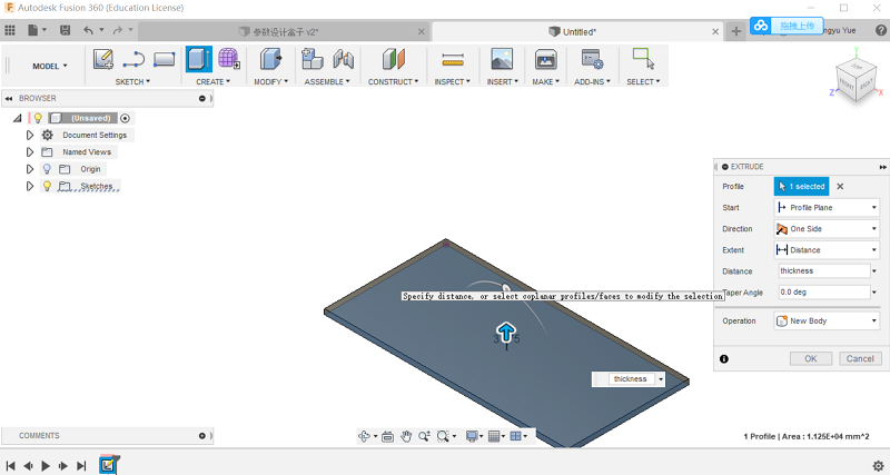
First , I drew a triangle,set the measurement as lenth and width. Then I extrude it with the distance as "thickness".
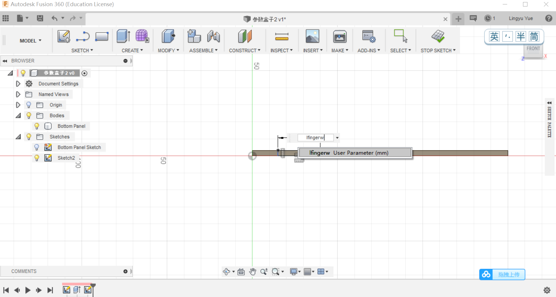
Sketch on the side and scale the width as lfingerw.
.png)
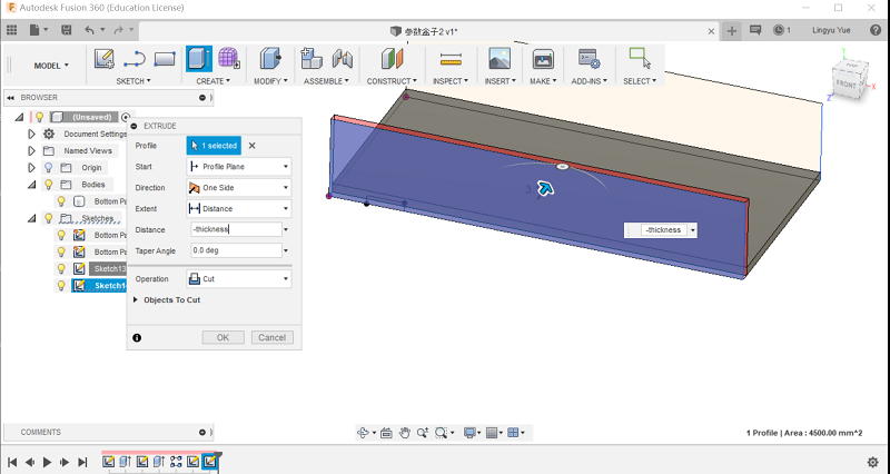
Extrude the side ,set the distance as "-thickness"
.png)
.png)
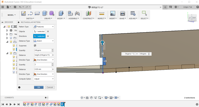
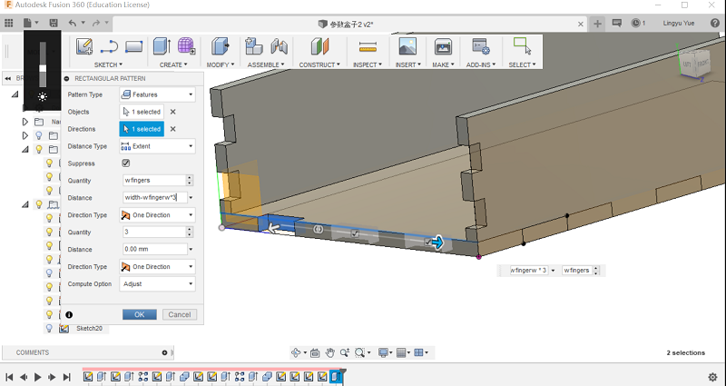
Click Create - Pattern-Rectangular Pattern and set the parameters.
.png)
.png)
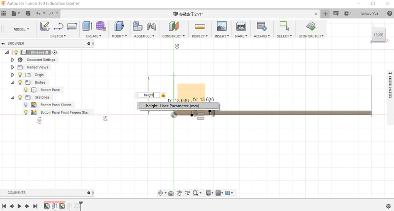
Sketch the side panel on the side of the rectangular. Set the height as "User Parameter height" .
Extrude it, when you need to extrude, you could press the keyboard E button, select the face you wanted to extrude and type the distance.
.png)
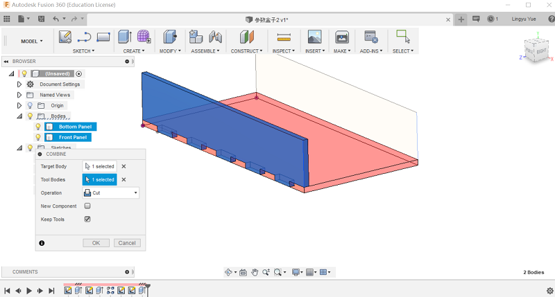
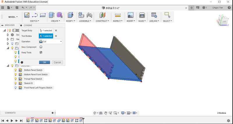
Modify-Combine, remeber to select keep tools,or else the tool will be deleted.
Use the same method to add notches on the side panel.
Create - Extrude - Start -"from object " Click this to copy a side panel.
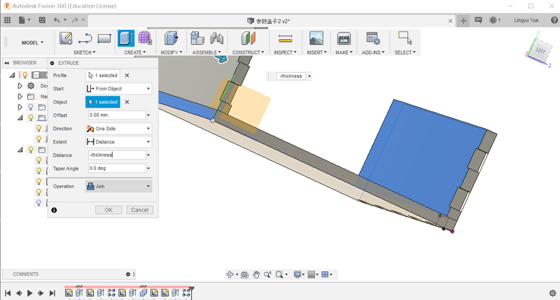
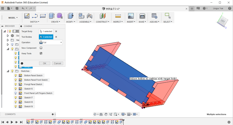
Cut side panel to get notches.
Draw nothes on the side of the bottom panel.
Draw the third side panel and cut.
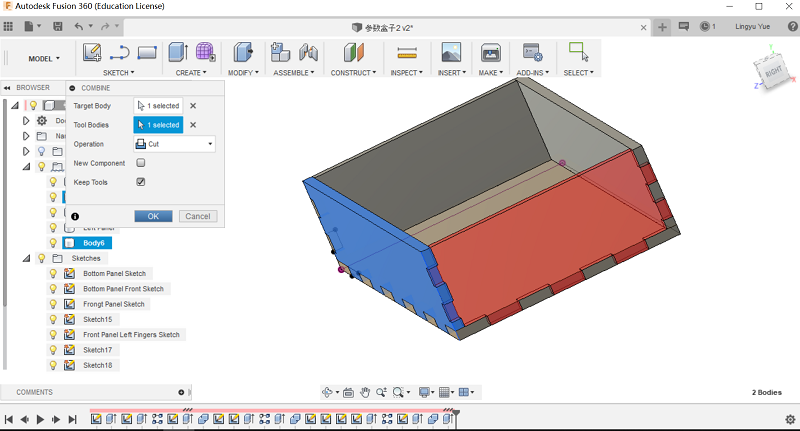
Finally, cut the fourth panel with the other panels. Box done. We could change the size of the box easily.
The laser cutter at MG Space is Nova laser cutter from thunder laser.
The chart below is the parameters we often used as usual.
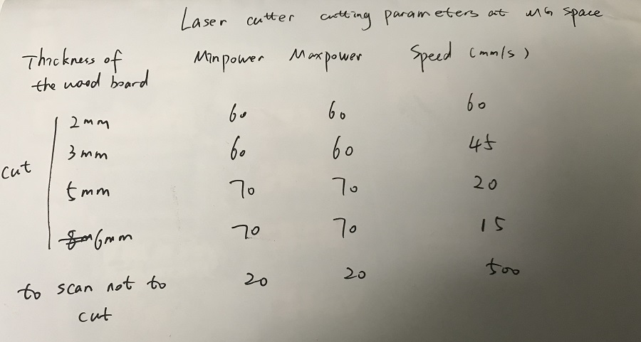
But for one laser mirror , cause we use laser cutter a lot to make the product prototypes , so after 2 months, we'll adjust the power a little bit, usually add some more to test before cutting.
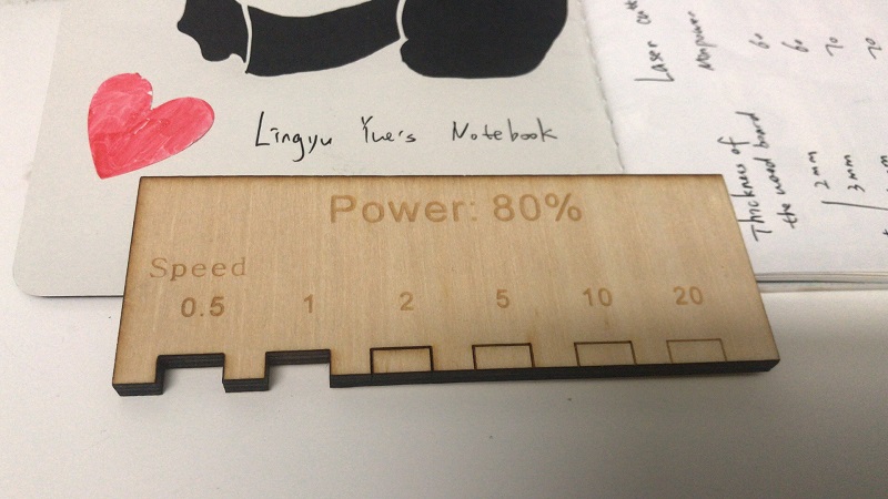
Instructor Yufei Ma reminded me that we could use the laser test piece to show and test. We used 5mm board and 90% power to test.
Here are the design -files I made this week:
- Cardboard Blocks (.lcp) // Press-fit construction
- Light Cube (.dxf) // Press-fit construction
- final-lasercut-files (.rar) //final-lasercut-files
- parameter design box v3 (.f3d) //parameter design box v3