Netwoking and Communications
Assignments
- Individual assignment: design, build and connect wired/wireless node(s) with network or bus addresses.
- Group assignment: send a message between two projects.
For this week , I wanna design a I²C bus. The I²C bus was designed by Philips in the early 80s to allow easy communication between componets which reside on the same circuit board. And it allow multiple "slave" digital integrated circuits(chips) to communicate with one or more "master" chips.
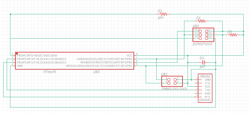
Draw the bridge schematics.
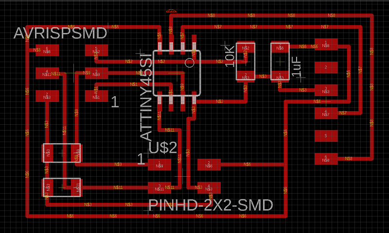
Arrange the wires and the export to png image.
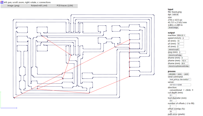
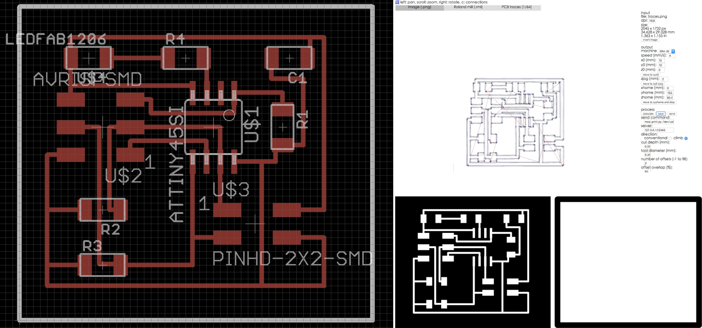
I use fabmodule to genetare the rml file and use Roland SMR-20 to mill the board. In fabmodules, I set the input png dpi to 1500 and calculate the milling path. 1/64 endmill for traces and 1/32 endmill for interior. And I set the number of offsets as "1"
Draw the node schematics.
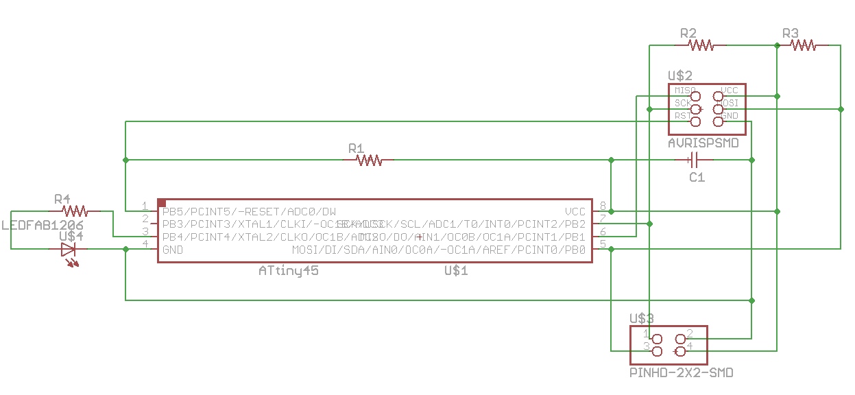
Export the png file and mill the board.
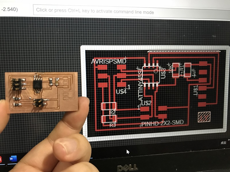
I soldered two boards.
I use arduino uno as ISP to make the bootloader.
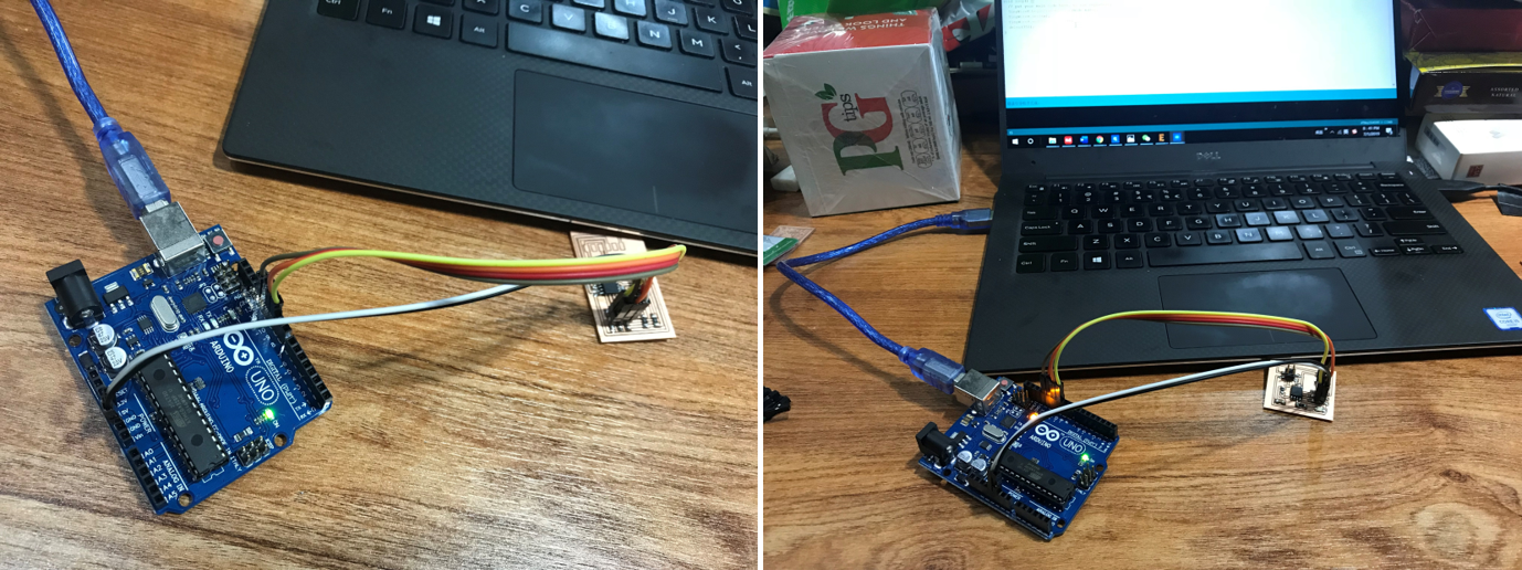
And then progamme the two boards.
The bridge
        #include  "TinyWireM.h" // I2C Master lib for ATTinys which use USI
        #define Node_Addr   0x11
        byte x = 0x01;
        void setup() {
          // put your setup code here, to run once:
          TinyWireM.begin();                    // initialize I2C lib
        }

        void loop() {
          // put your main code here, to run repeatedly:
          TinyWireM.beginTransmission(Node_Addr);
          TinyWireM.send(x);                 // if one-shot, start conversions now
          TinyWireM.endTransmission();          // Send 1 byte to the slave
          delay(750);                           // if one-shot, must wait ~750 ms for conversion
        }
The node
        #include "TinyWireS.h"     // wrapper class for I2C slave routines
#define Node_ADDR   0x11              // 7 bit I2C Address for Node
#define Led_Pin         4
byte x = 0x00;
bool ledState = false;

void setup() {
  // put your setup code here, to run once:
  pinMode(Led_Pin,OUTPUT);
  TinyWireS.begin(Node_ADDR);
}

void loop() {
  // put your main code here, to run repeatedly:
  if (TinyWireS.available()){           // got I2C input!
    x = TinyWireS.receive();     // get the byte from master
    if(x == 0x01){
      if(ledState == false){
        ledState = true;
        digitalWrite(Led_Pin,HIGH);
      }else{
        digitalWrite(Led_Pin,LOW);
        ledState = false;
      }
    }
  }
  delay (10);
}
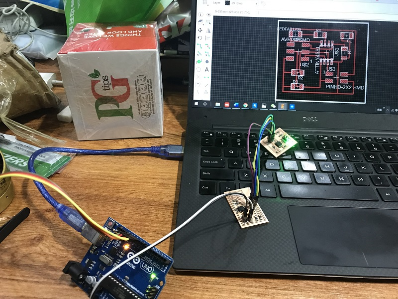
After soldering the board , I wrote a note to help me understand the wiring diagram.

Here are the design files :

