
Lingyu Yue @ FAB LAB Szoil · 2019
© 2019 Lingyu Yue · Template by Bootstrapious

This work is licensed under a Creative Commons Attribution-NonCommercial-ShareAlike 4.0 International License.
Final Project
- Create your own integrated design
- Demonstrate 2D & 3D modelling capabilities applied to your own designs
- Select and apply appropriate additive and subtractive techniques
- Demonstrate competence in design, fabrication and programming of your own fabbed microcontroller PCB, including an input & output device
A nice handmade stuff on your working table will make feel cozy during worktime.
And a good tool could remind you of the workflow and limited time. Therefore, my final project is a a flip calendar with a RGB light with the function of tomato clock.
It will flip with a pleasant click on 10am every morning when I am about to start my work at my office. And if you press the button, the RGB will light up when the coutdown ( you set before) ends.
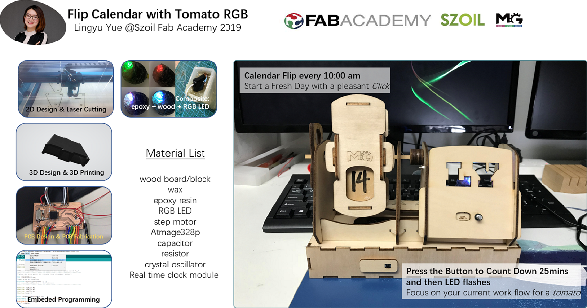
As I mentioned before , to remind me a good working habit and pleasant me.
- Make the frame and base of the calandar, conect the axle of step motor to the wood stick to let them rotate together.
- Programe it to make the step motor rotate at specific time everyday and the RGB will light up when countdown ends.
| FABRICATED PART | WEEKLY ASSIGNMENT | PROCESS | MACHINE AND TOOLS | SOFTWARE |
|---|---|---|---|---|
| The Frame and Base | Week 4 * | 2D Designing and Laser cutting | Laser Cutter | Inkscape, Fusion 360, Lasermaker |
| Wood blocks hoder | Week 6 | 3D Designing and Printing | 3D Printing | Solidworks |
| Resin RGB Light | wild card week | Resin and composite | Grinding Machine | |
| PCB board fabrication | before deadline | PCB design and fabrication | ||
| FabTinyISP -programmer (ATtiny44) | Week 5 | Electronics Production | Milling Machine, Soldering station | Roland VPanel for SRM-20 |
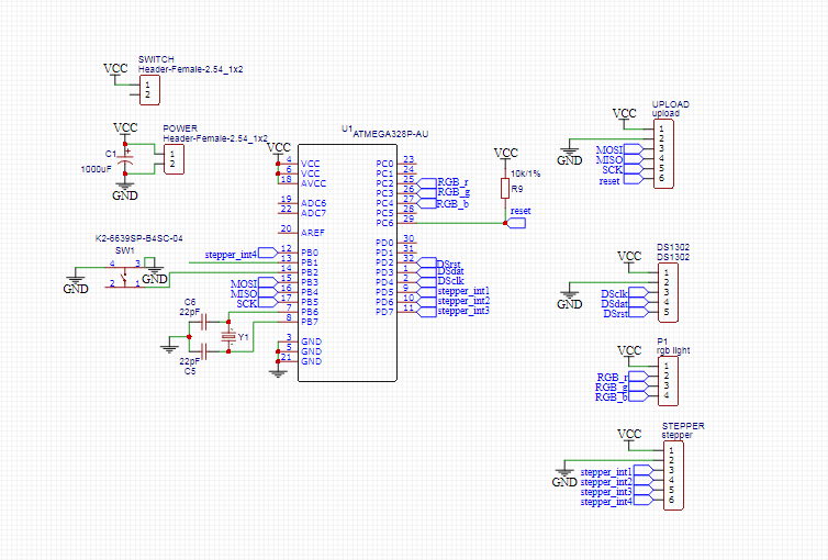
Atmage 328p board Design
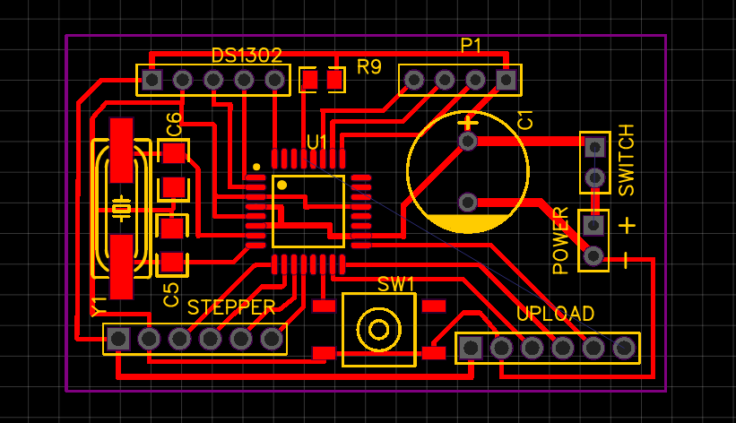
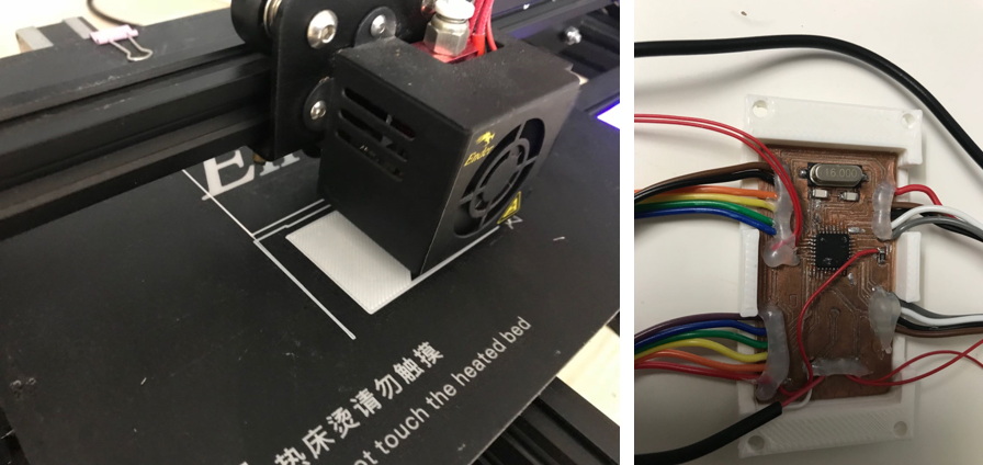
Atmage 328p board Milling
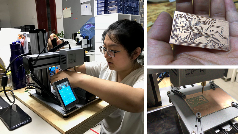
For milling the PCB, I tried to use snapmaker milling machine at my office, but I failed , cause I cant't generate Gcode file and I insert a png file to cut, and the endmill just cut line by line and scrub the cooper off. So I went to Szoil to finish cutting. After a few timis failure , I cut 4 boards and bring them back to MG.
Soldering
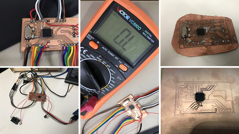
When I soldered at office, my cowork Jianfeng taught me a efficient method to solder the IC. I used to solder one pin by another. But Jianfeng showed to me that I could drag the tin along all the pins and catch the right time to shake the useless part away. I tried for 2 boards , first one failed, so I took apart the componets to solder the second one, luckily, it worked. I used multimeter to check the circuit, it was OK.
Download bootloader
I followed the Arduino as ISP instruction, made arduino ISP which is easy and then did the bootloader.
I failed to do the bootloader, and Jianfeng help me to check if the circuit is shorted.It proved that the PCB board is OK. And Huanghao helped to to observe the wave of the crystal oscillator with oscilloscope. Oscilloscope was also good.
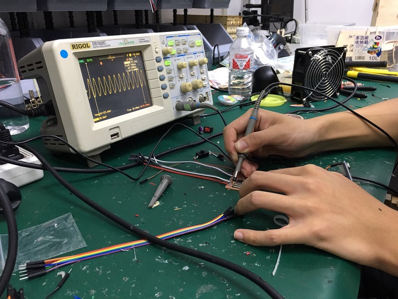
Later , I tried another aurduino uno as ISP, bootloader done, feel so happy!
Upload Code to atmega328p and test
| MATERIALS AND COMPONENTS | DETAILS | QUANTITY | COMES FROM |
|---|---|---|---|
| wood board | 3 mm,5mm,6mm ; 600*900mm | 1 each | local factory |
| atmega329p-pu | package-DIP28 | 1 | Szoil |
| 16Mhz/18pF Crystal | package-SMD 11.4x4.7mm | 1 | Taobao online shop |
| 22pF capacitor | package-1206 | 2 | Taobao online shop |
| 10k resistor | package-1206 | 1 | Szoil |
| step moter and step motor driver board | 28BYJ-48,5V,DC | 1 | Taobao online shop |
| button | TSTPHW 4 pin | 1 | Taobao online shop |
| MH-real-time clock modules-2 | ds1302 | 1 | Taobao online shop |
| jumper wire | / | several | find from the office box |
The programming
When I programmed the board to achive the functions, I struggled a lot , cause there were many errors showed , so I need to debug again and again. And I stayed late in the night for finishing before deadline, it's quiet around me, so I wisper to the board , please run the code and done.
I use two libraries online :arduino-ds1302-master and CheapStepper-master
Code for the clock module, the origin code for interfacing with the DS1302 timekeepin chip is wrote by Matt Sparks,2009.
#include
#include
namespace {
// Set the appropriate digital I/O pin connections. These are the pin
// assignments for the Arduino as well for as the DS1302 chip. See the DS1302
// datasheet:
//
// http://datasheets.maximintegrated.com/en/ds/DS1302.pdf
const int kCePin = 2; // Chip Enable
const int kIoPin = 3; // Input/Output
const int kSclkPin = 4; // Serial Clock
// Create a DS1302 object.
DS1302 rtc(kCePin, kIoPin, kSclkPin);
String dayAsString(const Time::Day day) {
switch (day) {
case Time::kSunday: return "Sunday";
case Time::kMonday: return "Monday";
case Time::kTuesday: return "Tuesday";
case Time::kWednesday: return "Wednesday";
case Time::kThursday: return "Thursday";
case Time::kFriday: return "Friday";
case Time::kSaturday: return "Saturday";
}
return "(unknown day)";
}
void printTime() {
// Get the current time and date from the chip.
Time t = rtc.time();
// Name the day of the week.
const String day = dayAsString(t.day);
// Format the time and date and insert into the temporary buffer.
char buf[50];
snprintf(buf, sizeof(buf), "%s %04d-%02d-%02d %02d:%02d:%02d",
day.c_str(),
t.yr, t.mon, t.date,
t.hr, t.min, t.sec);
// Print the formatted string to serial so we can see the time.
Serial.println(buf);
}
} // namespace
void setup() {
Serial.begin(9600);
// Initialize a new chip by turning off write protection and clearing the
// clock halt flag. These methods needn't always be called. See the DS1302
// datasheet for details.
rtc.writeProtect(false);
rtc.halt(false);
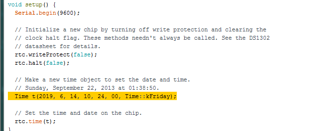
// Make a new time object to set the date and time.
// Sunday, September 22, 2013 at 01:38:50.
Time t(2019, 6, 14, 10, 24, 00, Time::kFriday);
// Set the time and date on the chip.
rtc.time(t);
}
// Loop and print the time every second.
void loop() {
printTime();
delay(1000);
}
For this part, what I do is to set the right time.
For step moter and RGB light, here's the correct code as below:
        //library
    #include
    #include

    //Please change these variables to suit your need ^_^
    /*****************************************************/
    //when do you want to rotate the stepper moter?
    int setHour=10;
    int setMinute=00;
    //set the direction
    boolean moveClockwise = 1;
    int countDownMinute = 3;//minute
    /*****************************************************/

    #define rgb_R A2
    #define rgb_G A3
    #define rgb_B A4
    #define btn 10

    bool countDownFlag = 0;
    unsigned long countDownTimer = millis();
    unsigned long resetStepper = millis();
    unsigned long debounce = millis();
    CheapStepper stepper (5,6,7,8);
    bool flag=0;

    namespace {
    const int kCePin   = 2;  //RST
    const int kIoPin   = 3;  //DAT
    const int kSclkPin = 4;  //CLK
    DS1302 rtc(kCePin, kIoPin, kSclkPin);
    }
    int timeData[3] = {8, 0, 0}; //hour,minute,second
    unsigned long reset = millis();

    void setup() {
      Serial.begin(9600);
      rtcSetup();
      rgbSetup();
      pinMode(btn, INPUT_PULLUP);
    }

    void loop() {
      // put your main code here, to run repeatedly:
      getTime();
      countDown();
      checkAlarm();
      Serial.print("hour: ");
      Serial.print(timeData[0]);
      Serial.print(" minute: ");
      Serial.println(timeData[1]);
      delay(10);
    }

    //setup functions

    void rgbSetup(){
      pinMode(rgb_R, OUTPUT);
      pinMode(rgb_G, OUTPUT);
      pinMode(rgb_B, OUTPUT);
      digitalWrite(rgb_R, HIGH);
      digitalWrite(rgb_G, HIGH);
      digitalWrite(rgb_B, HIGH);
    }

    void rtcSetup() {
      rtc.writeProtect(false);
      rtc.halt(false);
    }

    void countDown(){
      //get key
      if(!digitalRead(btn) && millis()-debounce>500){
        if(countDownFlag == 0){
          countDownFlag = 1;
        }else{
          countDownFlag = 0;
        }
        countDownTimer = millis();
        debounce = millis();
      }

      //light control
      if(countDownFlag == 1){//turn on the light
        digitalWrite(rgb_R, LOW);
        digitalWrite(rgb_G, LOW);
        digitalWrite(rgb_B, LOW);
      }else{//turn off the light
        digitalWrite(rgb_R, HIGH);
        digitalWrite(rgb_G, HIGH);
        digitalWrite(rgb_B, HIGH);
      }

      checkCountDown();
    }

    void getTime() {
      Time t = rtc.time();
      timeData[0] = t.hr;
      timeData[1] = t.min;
      timeData[2] = t.sec;
    }

    void checkAlarm() {
      if(millis()-resetStepper>100000 && flag == 1){
        flag = 0;
      }
      if (timeData[0] == setHour) { //hour match
        if (timeData[1] == setMinute) { //minute match
          if(flag == 0){
            flag = 1;
            stepperRotate();
            resetStepper = millis();
          }

        }
      }
    }

    void checkCountDown(){
      if(countDownFlag == 1 && millis()-countDownTimer>=countDownMinute*60000){
          countDownFlag = 0;
          countDownTimer = millis();
          countDownAlarm();
      }
    }

    void countDownAlarm(){
      for(int i=0; i<2; i++){
        digitalWrite(rgb_R, HIGH);
        digitalWrite(rgb_G, HIGH);
        digitalWrite(rgb_B, HIGH);
        delay(500);
        digitalWrite(rgb_R, LOW);
        delay(500);
        digitalWrite(rgb_R, HIGH);
        digitalWrite(rgb_G, LOW);
        delay(500);
        digitalWrite(rgb_G, HIGH);
        digitalWrite(rgb_B, LOW);
        delay(500);
        digitalWrite(rgb_R, HIGH);
        digitalWrite(rgb_G, HIGH);
        digitalWrite(rgb_B, HIGH);
        delay(500);
      }
    }
    void stepperRotate(){
        for (int s=0; s<2080; s++){
          stepper.step(moveClockwise);
          int nStep = stepper.getStep();
        }
      Serial.println("time is up");
    }
The tomato clock structure & appearance
First, I designed the canlendar part. I like the flip calendar a lot.
Laser Cut Perpetual Flip Calendar I get my initial idea from this website to make a flip calendar.
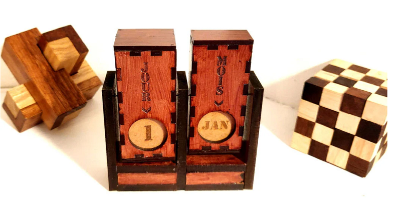
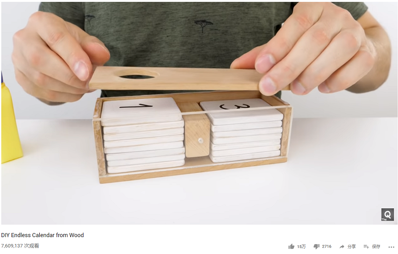
And I figure out how to design the flip part from this youtube video DIY Endless Calendar from Wood I knew that I could make several wood blocks with a part to divide them.
So I draw 15 wood blocks and test to cut, before assemble the calendar, I polish and wax the wood blocks.
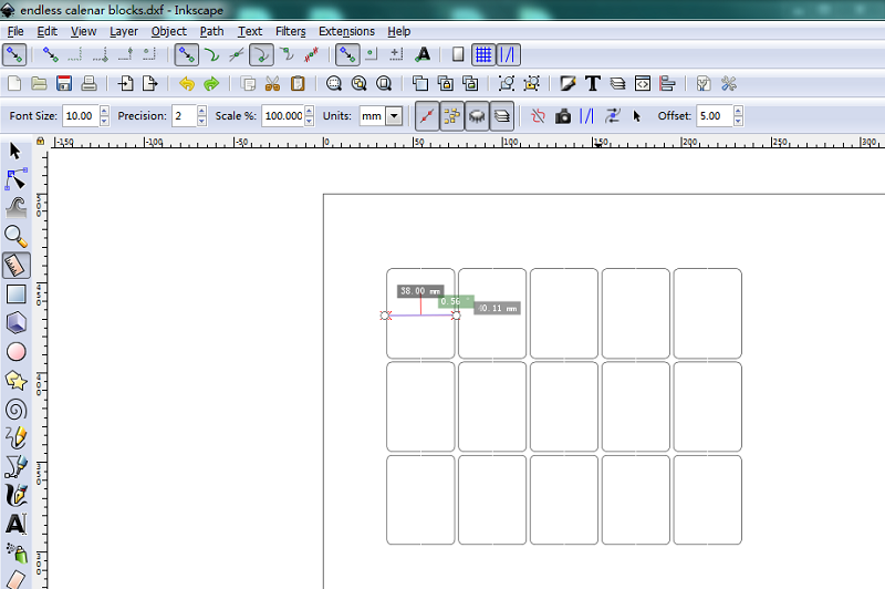
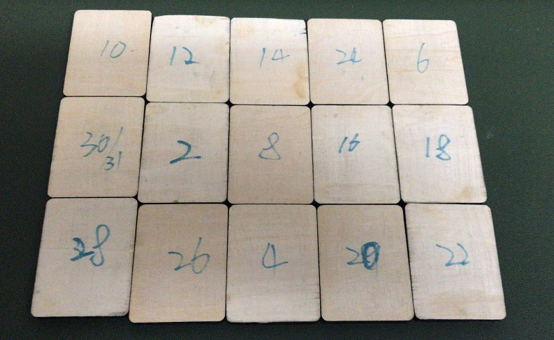
I found that if we laser the number on the blokcs , it will take long time to put all the blocks in the right order and it needed to be double side laser, easy to get errors. So for the next version, I will just cut 15 blocks, and write the numbers by hand after assembling.
I need the canlendar to flip automatically, so I'll put an axle in the middle , maybe a wooden cube with a hole but I need to drill the hole by hand, then I thought, a 3D print part will be better.
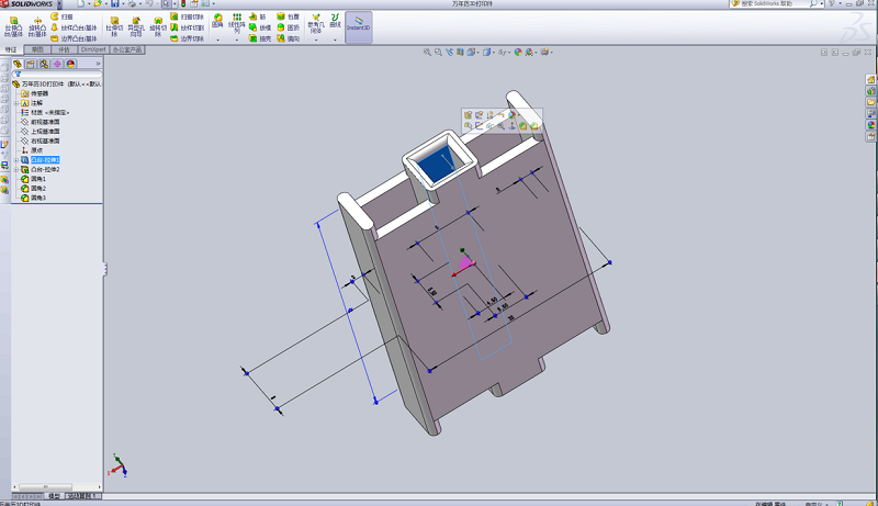
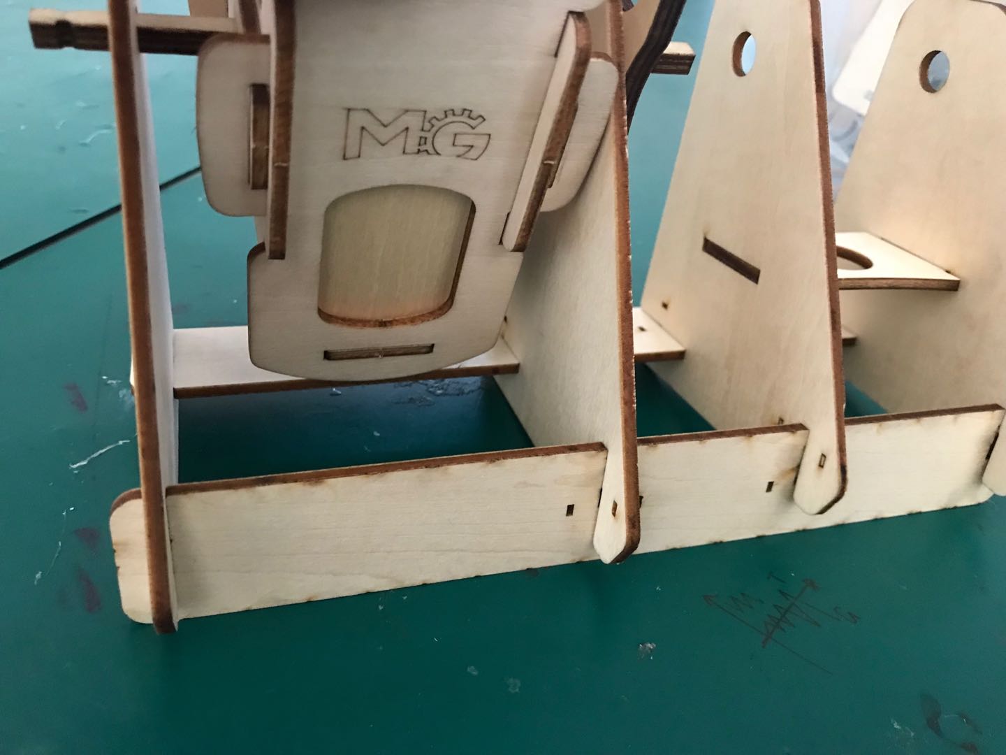
Then I designed the parts to hold the blocks which showed the date.
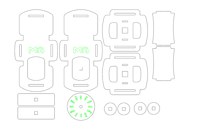
For the frame parts, I tried several times, first time ,I uesd staight pieces underneath, use two parts in different directions to hold the vertical pieces. But I didn't realize that, the flip part can't go through the horizontal parts with the simple rectangle shapes.
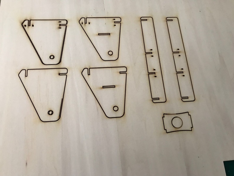
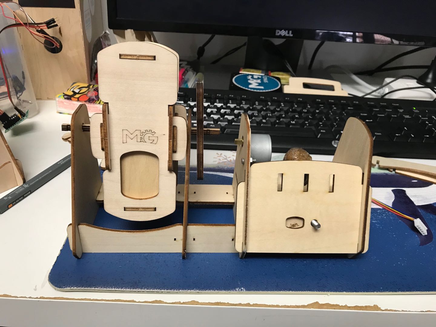
Then I redraw the frame with curves on the left, it worked.
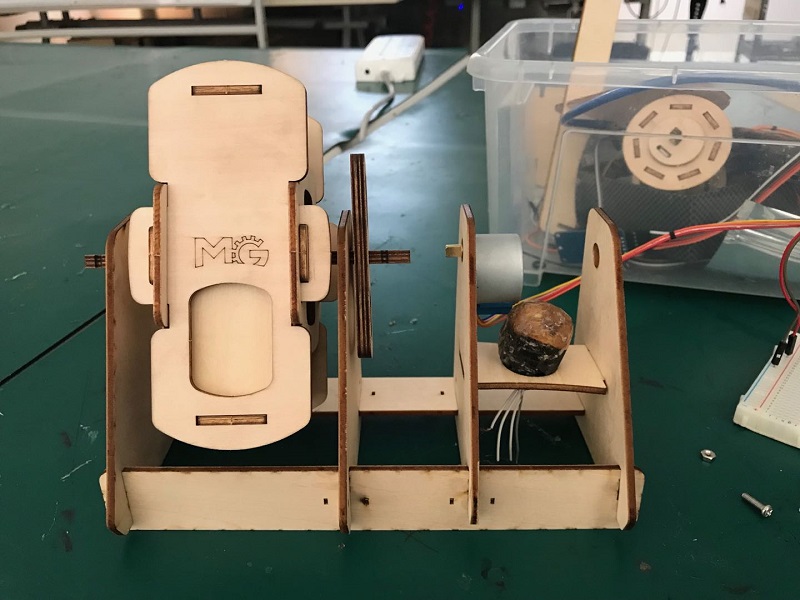
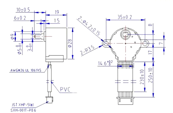
For the step motor part, at first, I measure the motor and roughly draw the outline. Then is came up to me that I could use the 28BYJ-48-dimensions to outline the sketch.
For connect the motor axle and the wood stick, I thought of making a 3D printing part ar first and I downloaded the step motor's axle connector 3D file. Then my coworker Yuanhan told me , we could simply design a laser cutter axle connector. So I draw 3 circles with holes which one of them fit the wood stick and one of them fit the motor axle, and I use two holes to connect them together.
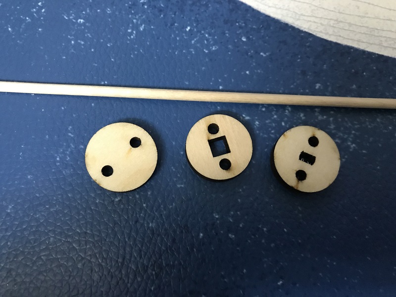
For the final assemble, I used two with wood stick holes and one with step motor axle hole.
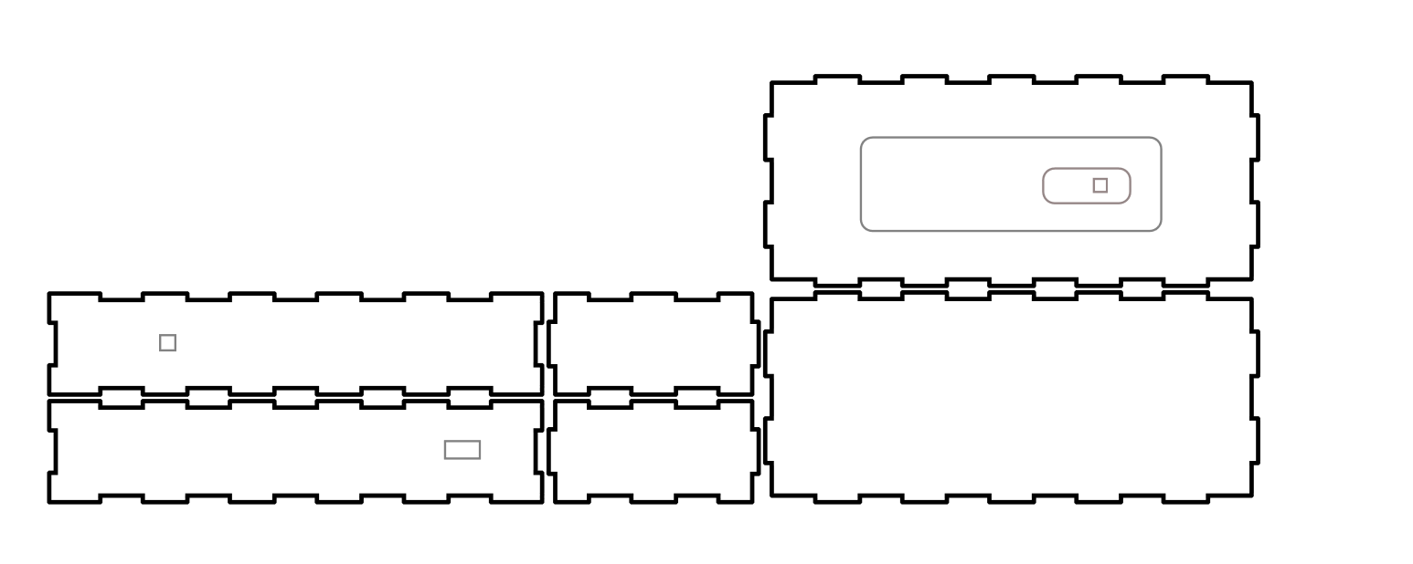
For the base to hold the elctronics part, I use Makercase website to design a box and then draw the port for my usb and button.
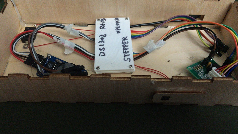
The encapsulation for the PCB board
When I tested the functions , I just put the board and all the wires in the base case. After testing successfully, I designed a 3D print part to fix the PCB board onto the base board.
Printed and assemble the encapsulation.
Details in the Week 18 -Resin the RGB light