Embeeded Programming
individual assignements
-read a microcontroller data sheet -program your board to do something,with as many different programming languages and programming environments as possible
group assignements
- compare the performance and development workflows for other architectures
Individual Work
Avr Programming
I've decided to do my program with AVR writing in C code because I 've studied at university the languages C. For my programming I' ve used the PCB BOARD used in the week of electronic design where I put a:
- led between vcc and gnd
- a led and a button in two pin free
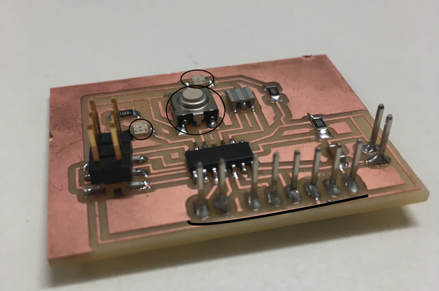
My idea is to do a programm which blink the led without the button and an other which to the same thing but with the button.
So I do two .c files:
-the first: led_without_button.c -the second: led_with_button.c
#include <avr/io.h>
#include <util/delay.h>
#define LED_OUTPUT  DDRA        //this define let me do LED_OUTPUT instead of DDRA when I set the output led pin
#define DELAY_TIME 1000
int main(){
CLKPR = (1 << CLKPCE);                                                    //I prescale the clock division to 1
CLKPR = (0 << CLKPS3) | (0 << CLKPS2) | (0 << CLKPS1) | (0 << CLKPS0); //every bit of CLKPS must be set in 0
int i;
LED_OUTPUT |= (1 << PA7);                     //set the pin output
while(1)                       // the blinking of theledisprogrammed in the while cycle
{
for(i=0;i<3;i++){
LED_PORT|= (1 << PA7);
_delay_ms(DELAY_TIME/10);
LED_PORT&=~(1 << PA7);
_delay_ms(DELAY_TIME/10);
}
LED_PORT|= (1 << PA7);
_delay_ms(DELAY_TIME);
}
return(0);
}
The second:
#include <avr/io.h>
#include <util/delay.h>
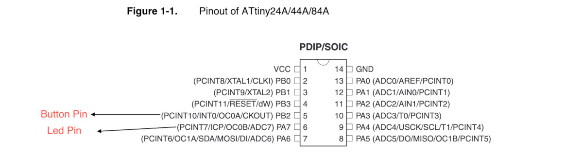
#define LED_PORTA PORTA //its port is PA7 (pin 6)
#define LED_OUTPUT DDRA //Led is an output
#define BUTTON_INPUT DDRB //its port is PB2 (pin 5) INPUT BUTTON
#define BUTTON_PULLUP PORTB //setting of pull_up internal
#define DELAY_TIME 100
int main(){
CLKPR = (1 << CLKPCE); //this is the presclar clock setting
CLKPR = (0 << CLKPS3) | (0 << CLKPS2) | (0 << CLKPS1) | (0 << CLKPS0);
int i;
LED_OUTPUT |= (1 << PA7); //the pin set as an output(led)
BUTTON_INPUT=~(1 << PB2); //the pin set as an input(button)
BUTTON_PULLUP|=(1<<PB2);
while(1)
{
if(bit_is_clear(PINB,PB2)){ //controll if the button is pressed
for(i=0;i<3;i++)
{
LED_PORTA |= (1 << PA7); //the cycle of the blinking of the led
_delay_ms(DELAY_TIME);
LED_PORTA&=~ (1<< PA7);
_delay_ms(DELAY_TIME);
}
LED_PORTA&=~ (1<< PA7);
}
else{
LED_PORTA&=~(1<<PA7);
}
}
}
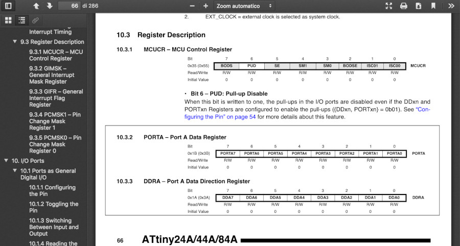
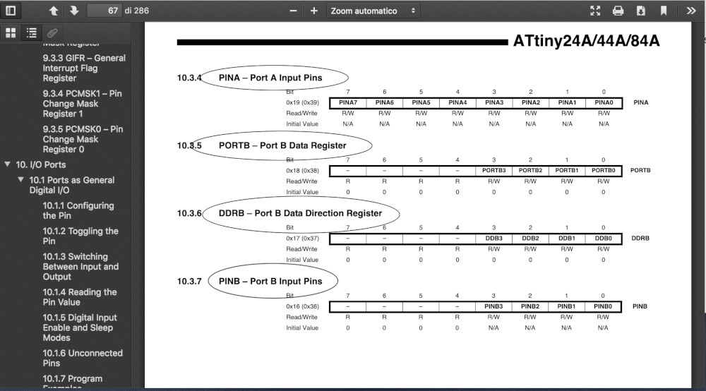
we can see that I have defined before the main() all the input and the output and I set them with the value of the :
- data direction register DDR followed by the letter of the port: DDRB for example in my case
- port (letter of the port): PORTB
- port input (letter of the port): PINB
we can see the structure of this register in the datasheet:
Arduino Programming
with arduino languages it's easier programming because the sintax is more intuitive. I do programm that do the same things of the C programm ones; I have changed only the language:
This is the arduino code: led_without_button:
  int ledPin=7;                     //the pin PA7 is the number 7
  void setup() {
  pinMode(ledPin,OUTPUT);            //set the led pin
  digitalWrite(ledPin,LOW);          //at the first the led is tunred-off
  }
  void loop() {                       //the blinking of the led
  int i;
  for(i=0;i<3;i++){
  digitalWrite(ledPin,HIGH);
  delay(100);
  digitalWrite(ledPin,LOW);
  delay(100);
  }
  digitalWrite(ledPin,HIGH);
  delay(1000);
  }
This is the arduino code: led_with_button:
  int ledPin=7;                                 //PA7 is in 7
  int button_pin=8;                             //PB2 in 8
  void setup() {
  pinMode(ledPin,OUTPUT);                      //the led is an output
  digitalWrite(ledPin,LOW);                    // the inizial state of led is low
  pinMode(button_pin,INPUT_PULLUP);                    //I set the resistor pull_up
  }
  void loop() {
  int i=0;
  if (digitalRead(button_pin)==LOW)          //the button is pressed if its state is LOW
  {
  for(i=0;i<3;i++){
   digitalWrite(ledPin,HIGH);
   delay(100);
   digitalWrite(ledPin,LOW);
   delay(100);
   }
  digitalWrite(ledPin,LOW);
  }
  else{
  digitalWrite(ledPin,LOW);
  }
 }
Differences between AVR programming in Arduino and C
While the AVR programming in C has sintax and features similar to the normal C language ; it has a bit differences in the operation of the bit when we declare and set a pin(in output or input); Arduino instead has the same declaration of the variable than C languages but different structure of programming: in fact the arduino programming is divided in two main blocks(function):
- the void setup: when we declare the variable and the iniziale state of it(when we launch the program)
- the void loop: in the loop there is what the programm does in loop
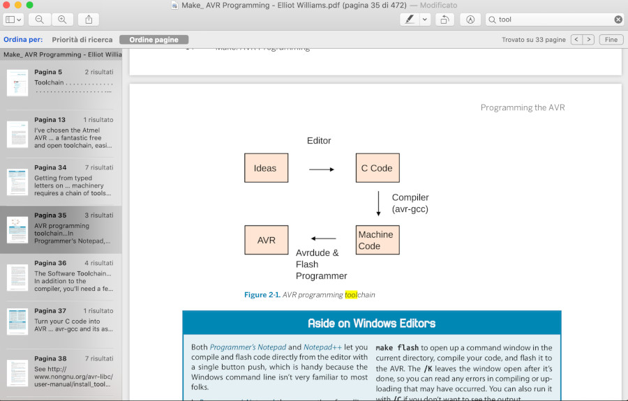
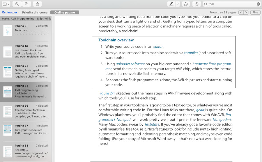
Toolchain AVR Programmming
For programming a Board we can do some step; this chain of process is called toolchain: there are below two screen which rappresent this concept very well:
In my case,I've decided to do a file "make" in which there are put the main command to programm(compilation,fuse,flash..) and then I run the make and which some other command I do all the process together.
this an exemple of a file make used to run the file.c led_without_button:
  PROJECT= led_without_button
  SOURCES=$(PROJECT).c
  MMCU=attiny44
  F_CPU = 20000000
  CFLAGS=-mmcu=$(MMCU) -Wall -Os -DF_CPU=$(F_CPU)
  $(PROJECT).hex: $(PROJECT).out
  avr-objcopy -O ihex $(PROJECT).out $(PROJECT).c.hex;\
  avr-size --mcu=$(MMCU) --format=avr $(PROJECT).out
  $(PROJECT).out: $(SOURCES)
  avr-gcc $(CFLAGS) -I./ -o $(PROJECT).out $(SOURCES)
  program-bsd: $(PROJECT).hex
  avrdude -p t44 -c bsd -U flash:w:$(PROJECT).c.hex
  program-dasa: $(PROJECT).hex
  avrdude -p t44 -P /dev/ttyUSB0 -c dasa -U flash:w:$(PROJECT).c.hex
  program-avrisp2: $(PROJECT).hex
  avrdude -p t44 -P usb -c avrisp2 -U flash:w:$(PROJECT).c.hex
  program-avrisp2-fuses: $(PROJECT).hex
  avrdude -p t44 -P usb -c avrisp2 -U lfuse:w:0x5E:m
  program-usbtiny: $(PROJECT).hex
  avrdude -p t44 -P usb -c usbtiny -U flash:w:$(PROJECT).c.hex
  program-usbtiny-fuses: $(PROJECT).hex
  avrdude -p t44 -P usb -c usbtiny -U lfuse:w:0x5E:m
  program-dragon: $(PROJECT).hex
  avrdude -p t44 -P usb -c dragon_isp -U flash:w:$(PROJECT).c.hex
  program-ice: $(PROJECT).hex
  avrdude -p t44 -P usb -c atmelice_isp -U flash:w:$(PROJECT).c.hex
I re-used the neil's file make used in the week of electronic design editing something for exemple: - the name of the file source.c
the purpose of my toolchain is having a file .hex from the source(.c) and then a file .out.: the totall command of the toolchain are:
 - make -f < name_file_make >
 - make -f < name_file_make > program-usbtiny
 - make -f < name_file_make > program-usbtiny fuse  // is a memory fixed
with this three command I have programmed my board.
Clock setting and the datasheet
As I have said before , I have done the make file taken the neil's file but setting the same fuse of it ,I have had problem with the delay of my programm. In fact the delay of 1000 msec(1) corresponded to 8000 msec(1). I solve the problem seeing the datasheet in the champter 6 (clock ) and the neil.s file in C:
the lfuse is set in 0x5E:
avrdude -p t44 -P usb -c usbtiny -U lfuse:w:0x5E:m
this configuration divedes the clock in 8 so if we decide to set this fuses value we have to add some line code in our source.c to set (by software) the division in 1(the same thing that neil've done)
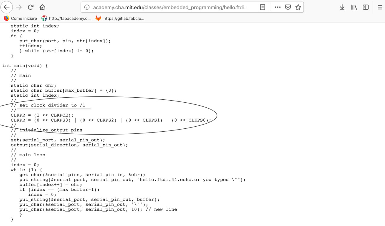
neil's file:
my file:
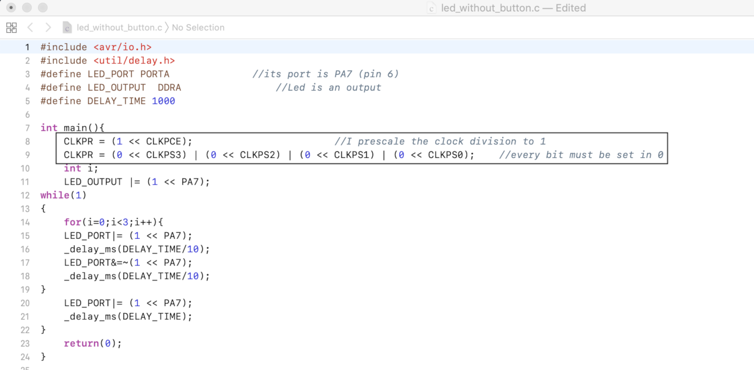
this lines code are expleined in the datasheet:
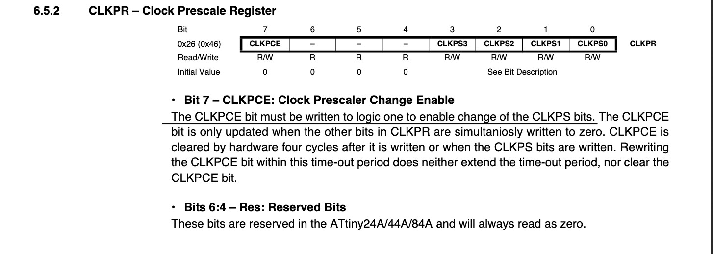
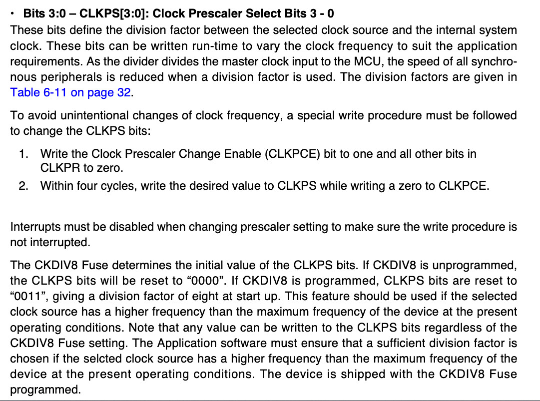
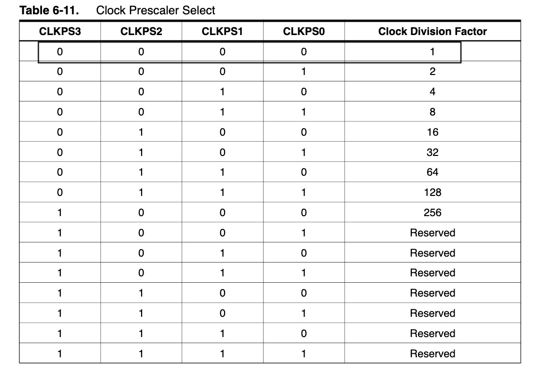
in synthesis with the first line code I can change the 4 bits of the CLKPS and set the prescalr division choosing the combination of this 4 bits :
CLKPR = (1 << CLKPCE);
this second line code set the prescalar division to 1:
CLKPR = (0 << CLKPS3) | (0 << CLKPS2) | (0 << CLKPS1) | (0 << CLKPS0);
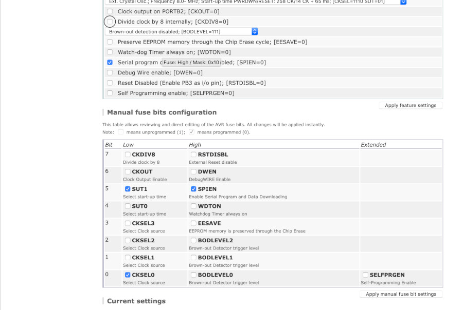
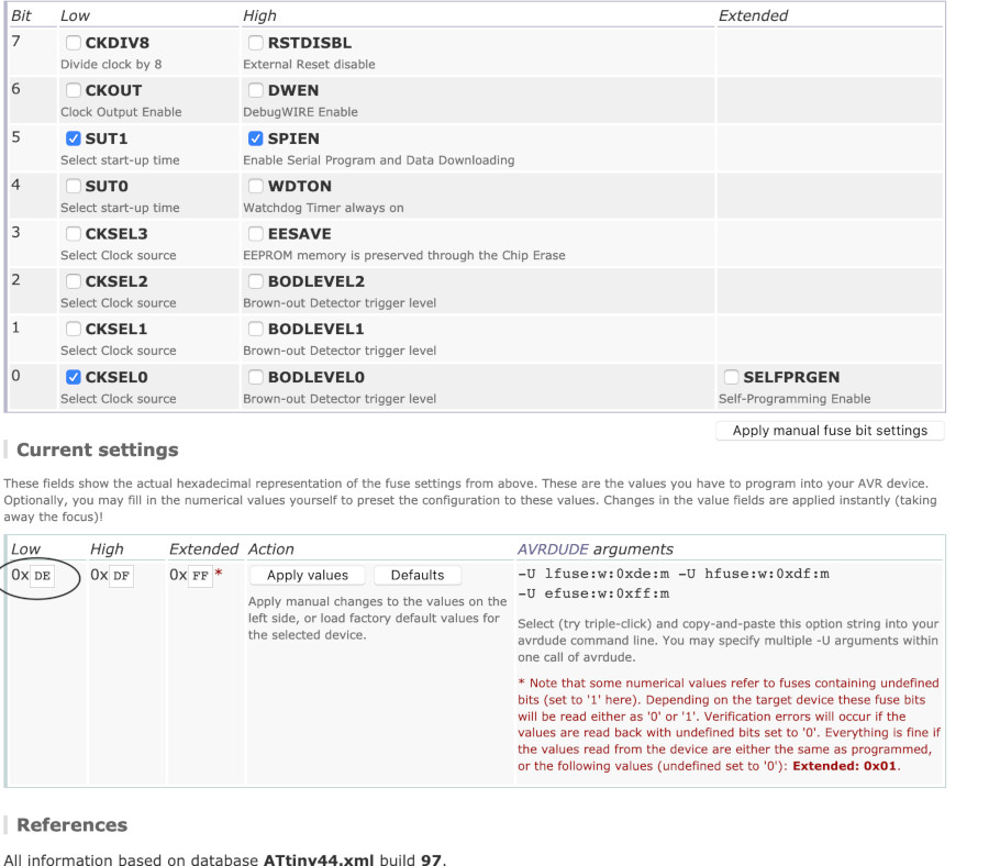
an other things that has the same result is changing the lfuses at the first without adding nothing code in our c file:
with this calculator of fuse I set the hexadecimal correct that gave me the prescalr division in 1: 0xDE as we can see in this screen:
this the programm: led with button (programmed in C):
then : led without button:
An other programming language: Python Circuit
I 've decided to blink a led with Circuit Python: to do it I read the datasheet of my microcontroller that I am going to programm and a download in this page the editor recommended to programm in pyhotn: Mu. Then I have read a tutorialfor the sintax of declaration digital input/output:
I do my code.py (led_without_button);
  import digitalio              //this is the module to controll digital output
  import board
  import time
  led = digitalio.DigitalInOut(board.D6)           // in this way I controll the pin 6
  led = digitalio.DigitalInOut.Direction.OUTPUT   // my led is an output
  while(1):                       // this is the cycle
  led.value= True
  time.sleep(100)
  led.value= False
  time.sleep(100)