Electronic design
Group assignement:
group project:
- use the test equipment in your lab to observe the operation of a microcontroller circuit board
Individual assignement:
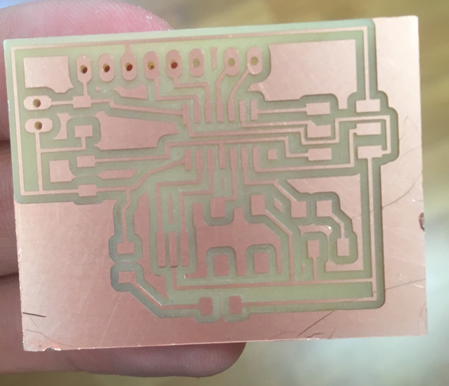
- redraw the echo hello- world board – add (at least) a button and Led (with current-limiting resistor)
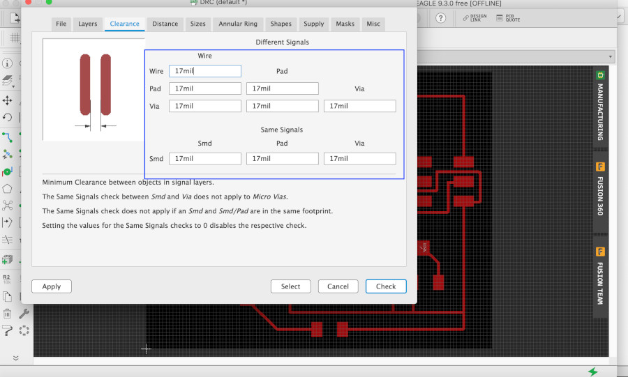
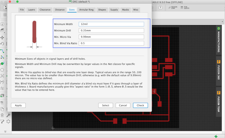
- check the design rules, make it and test it
- extra credit: simulate its operation
Individual work
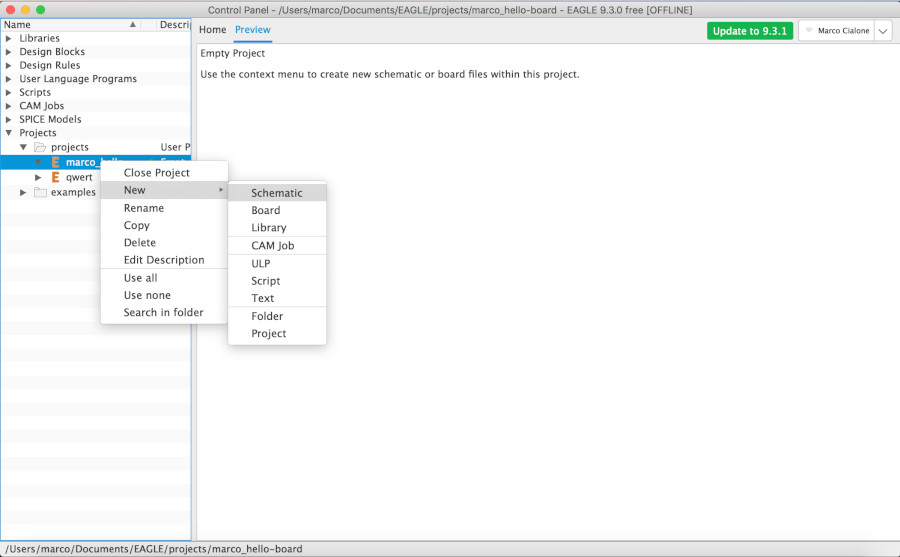
First of all, I have seen the echo hello world board to redraw in the site of fabacademy in order to have an idea of the final work. I used EAGLE programm to redraw my board because It's very simple to use it and learn its main process. The project of my board is divided in two part:
- the schematic
- the board
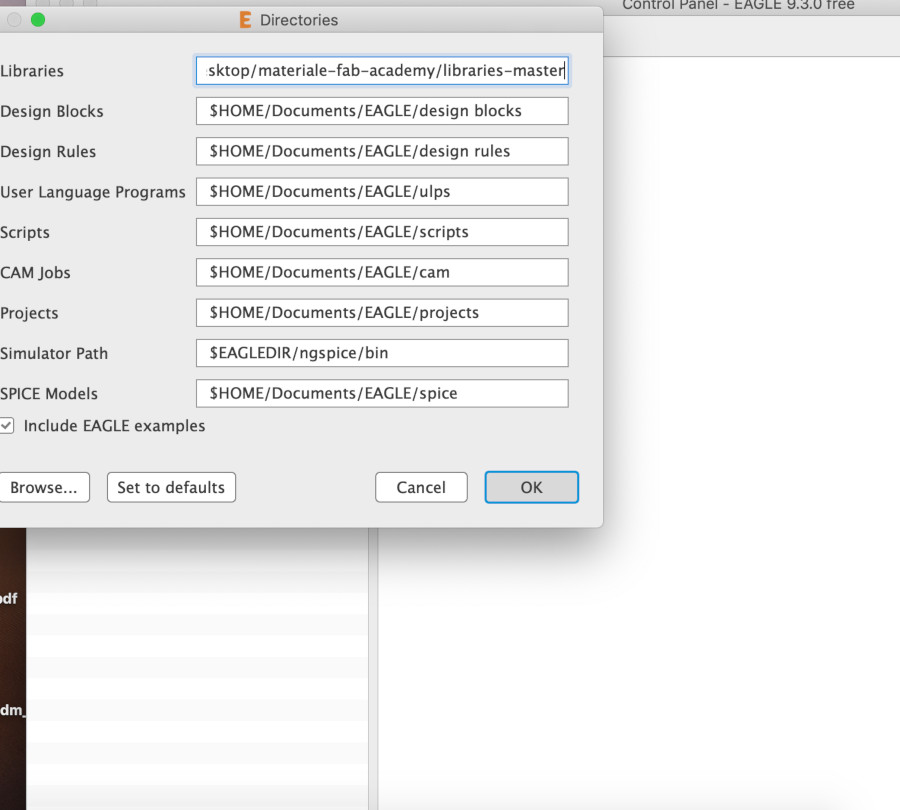
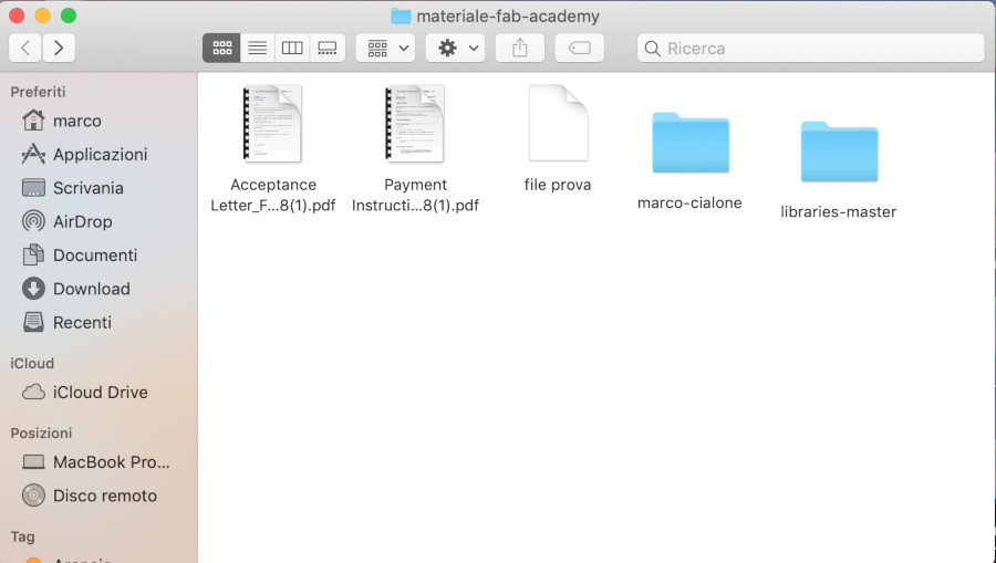
I set the library of fab-academy in my directory of fabacademy in order to have all the component that i need for my schematic.
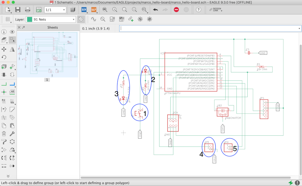
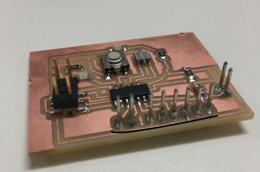
Schematic of my board
In my schematic I draw the basic board of the image seen before adding some new part; I decided to add:
- A button in the pin PB2: this button act ivates the pin.
- A led (with a resistor) in the pin PA7.
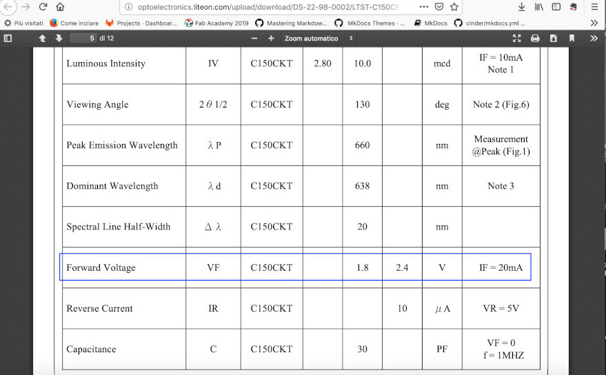 seeing the datasheet of the led I've seen the value of the led voltage and the current led and at the end I've calculated the value of the resistor with this formula:
Vled > Vcc- R x (current_led) ;
R > (Vcc - Vled )/Current_led ;
R > (5-1.8)/0.02 = 160 Ohm
We can set the value on 500 Ohm .
- An other led linked between the VCC and GND: this led is going to switch on when (and if)the board is powered well. In fact with this led we can see immediately if the microcontroller could work .(if the corrent pass between the VCC and GND); So if the led switchs on and the board doesn't work as we have programmed ,the problem certainly is not in its supply.
- A pair of exposed pin (one linked to Vcc and the other one to GND);
- an other pair of exposed pin(linked to the pin PA3 and PA2);
in that way we have all the pin of the microcontroller are in use;
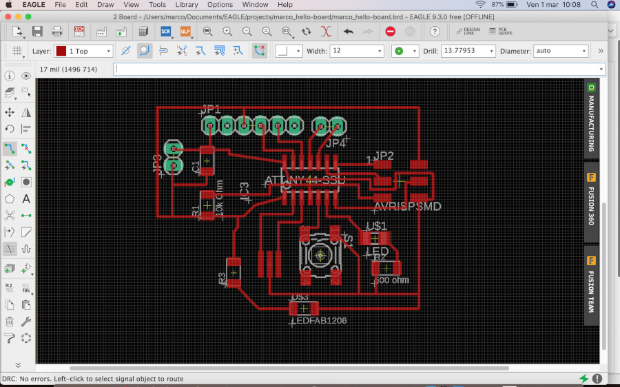
Board
When I have projected my schematic I set all the component that my circuict is going to have. I set in EAGLE the fisical limit of the tip of my milling machine.
But in the BOARD I am going to link every component in order to have a compact circuit with every component placed in the best way.
Creation of png
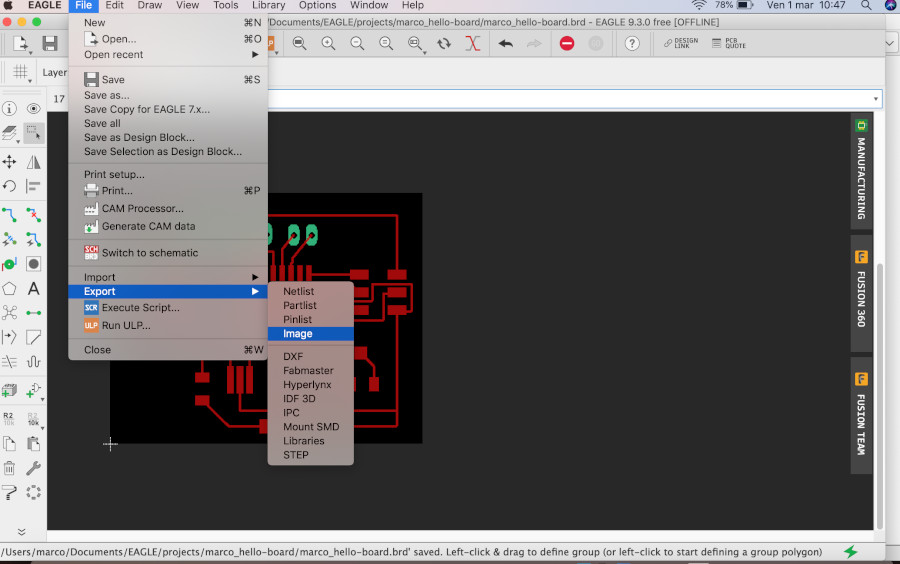
when I finish the design of my board I am going to export a png file in order to create a file .rlm for the milling machine.
I need to do some modification on my brd file in eagle.
- I resize the board around my circuit.
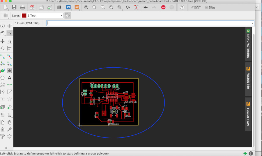
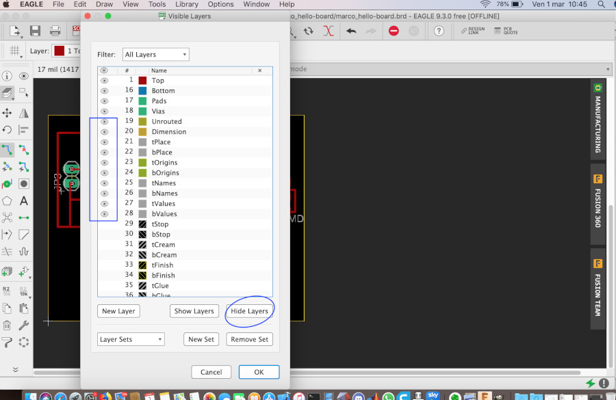
- I hide the name of the component because in the png file I am going to have only the trace and the outline and the place where put my component.
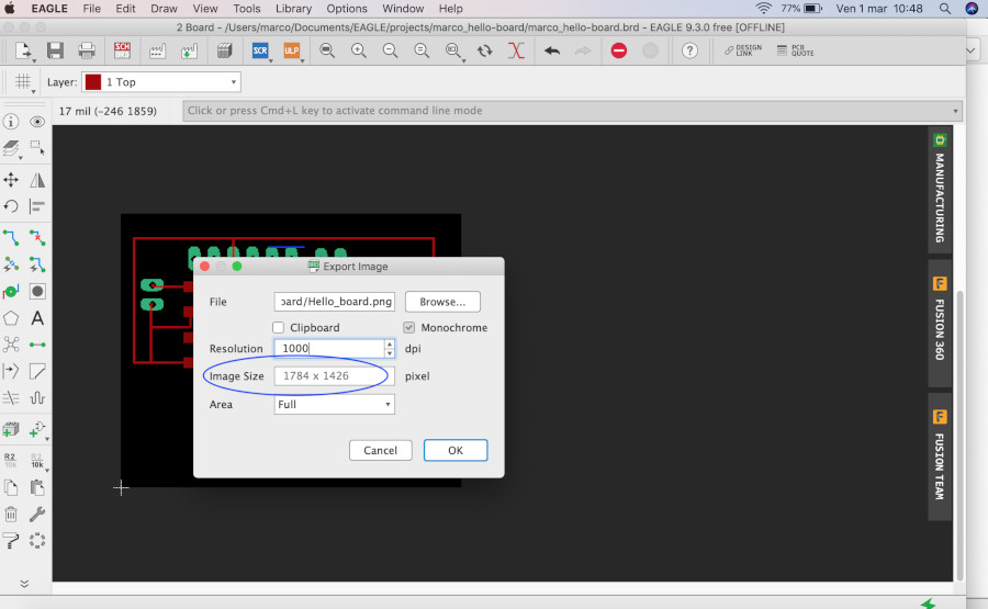
I export my file png :
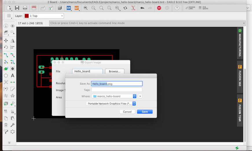
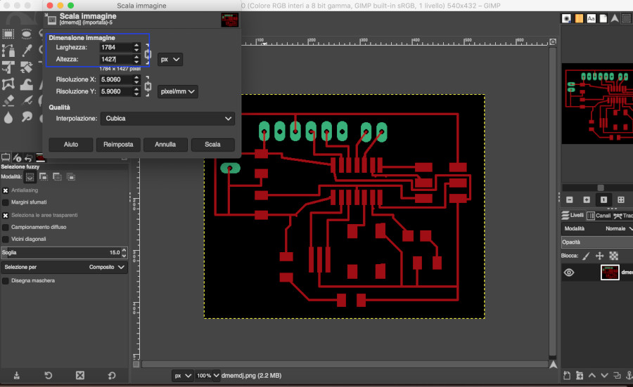
Then I open this file png on GIMP:
Because of a bug on eagle when I exported the png and edit it in Gimp, its size is double than the eagle's one so I have had to resize the png to mantain the original dimension.. the version of eagle that I've used is 9.3.0.. I don't know if it is only a problem of my version..for this week I've solved this problem in this way but I am going to test this bug in another computer..
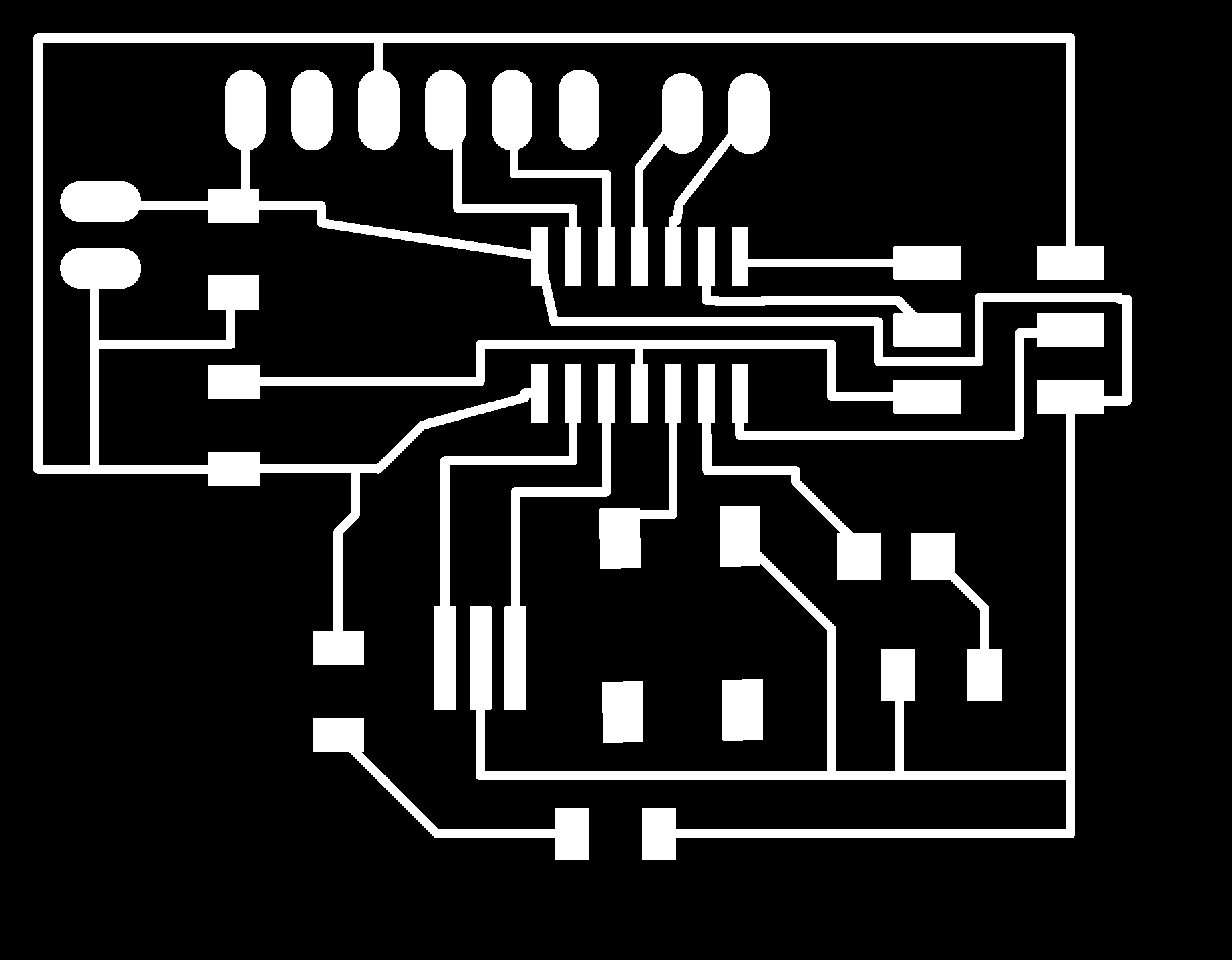
With gimp I do my file trace and outline and an other file for the milling of the holes :
this is my file trace:
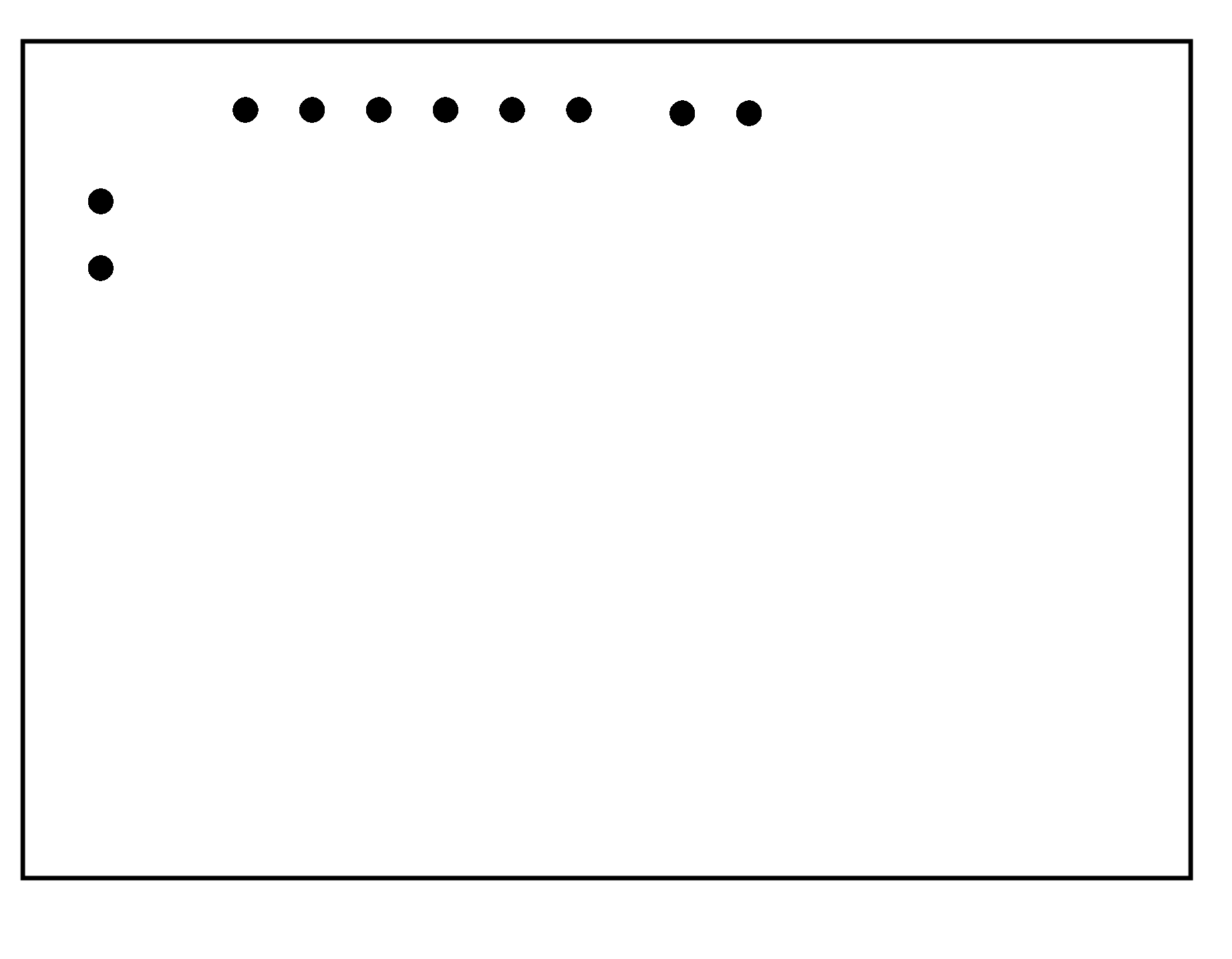
this is my file outline:

this is my file of the holes of my board:
The process of the building of the file rlm(read by the milling machine) is the same done in the Week5:electronic production
The test of my board
When I've made my board I have had to test it; the step I am going to do are:
- programm my board with a programmer (fab Isp)
- open I file and see the work of my board
the programming of my board
In order to programm my board I need to link my programmer with my board, the file echo.c andmake. I paste the content of this file in file echo and make and I put them in a directory:
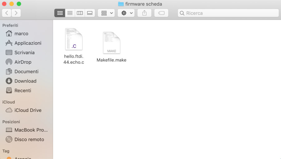
in the terminal , I go in the directory done bofore and digit :
make
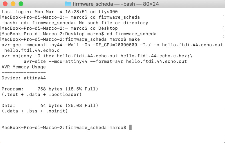
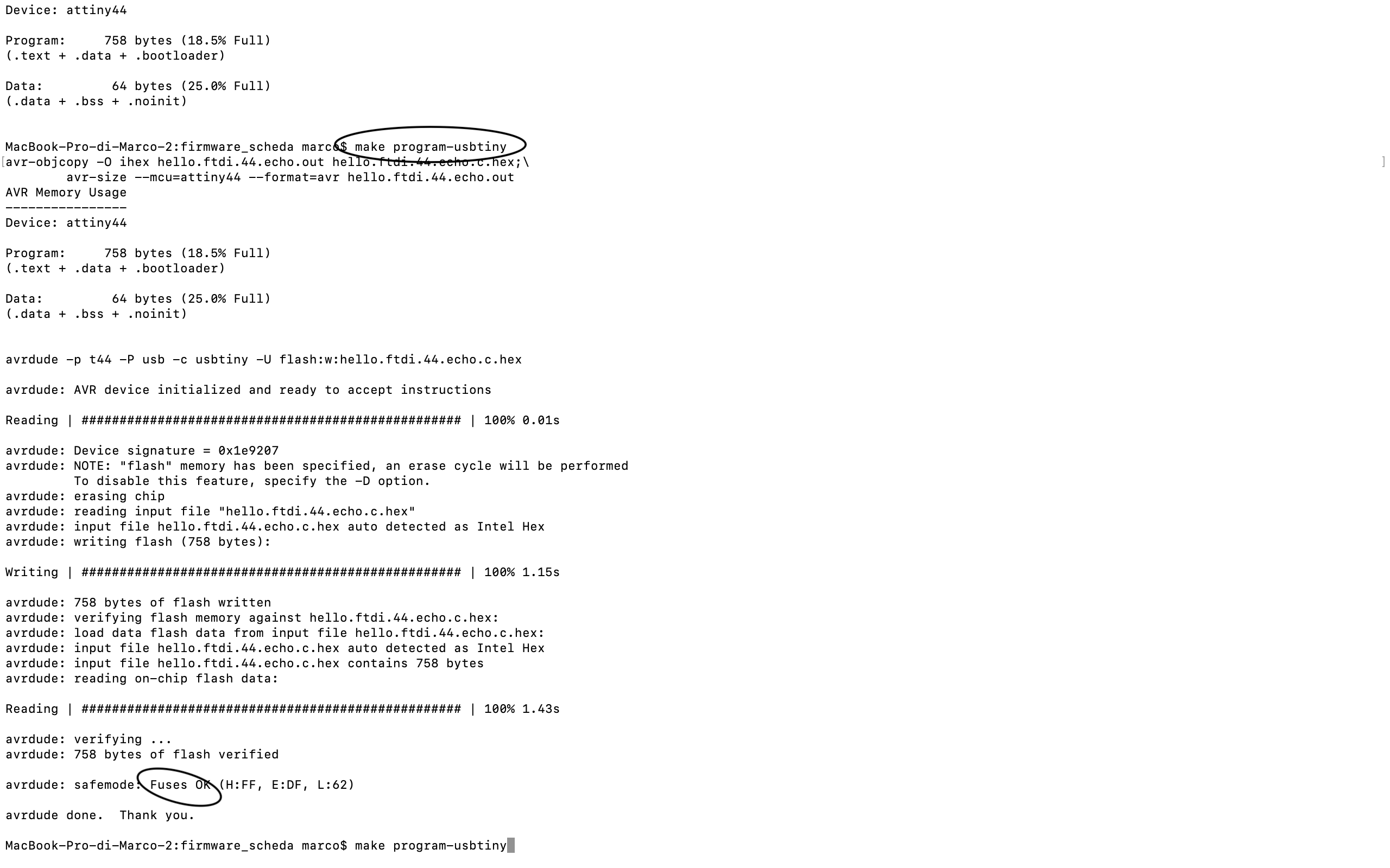
make program-usbtiny
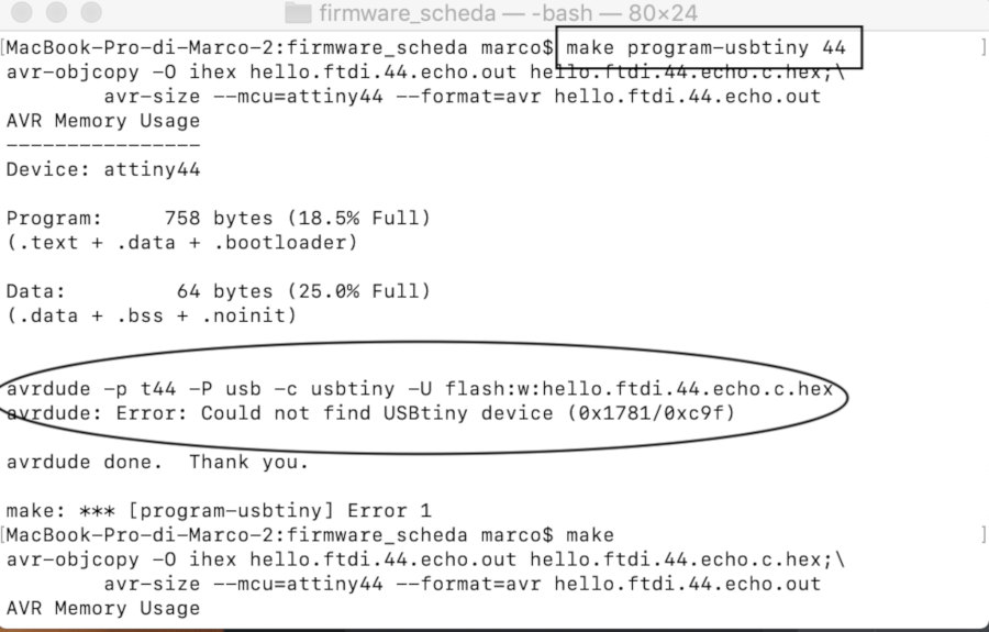
in this output I have had an error because the programmer wasn't recognized by the computer in the port usb where I put it. So I changed Usb port and after checked that the programmer is linked with my computer , I digit the command again and the output went well:
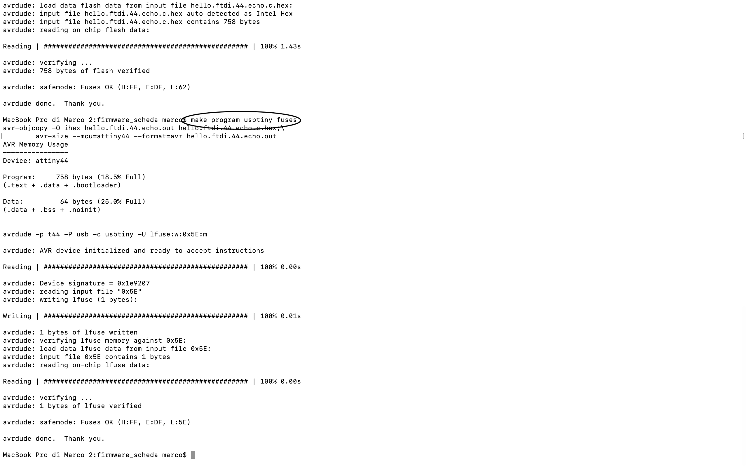
at the end I digit :
make program-usbtiny-fuses
The test of the working of the board
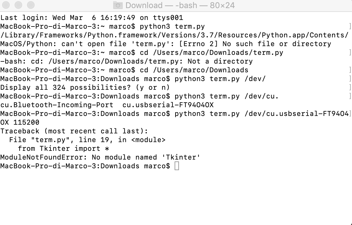
In order to have a verification of the working of my board I link my fdti cave on my board to my usb port and I have to launch a python file:
I digit:
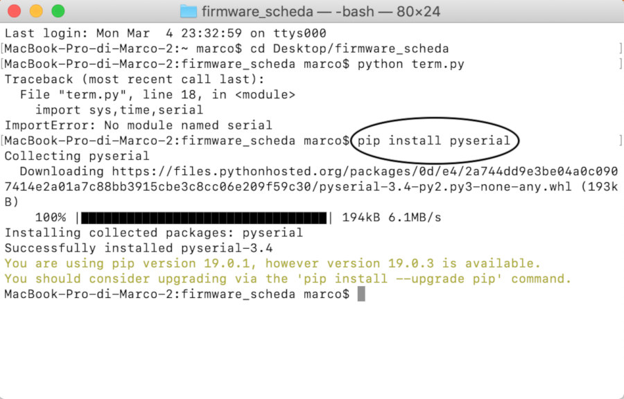
python term.py
and I have this output :
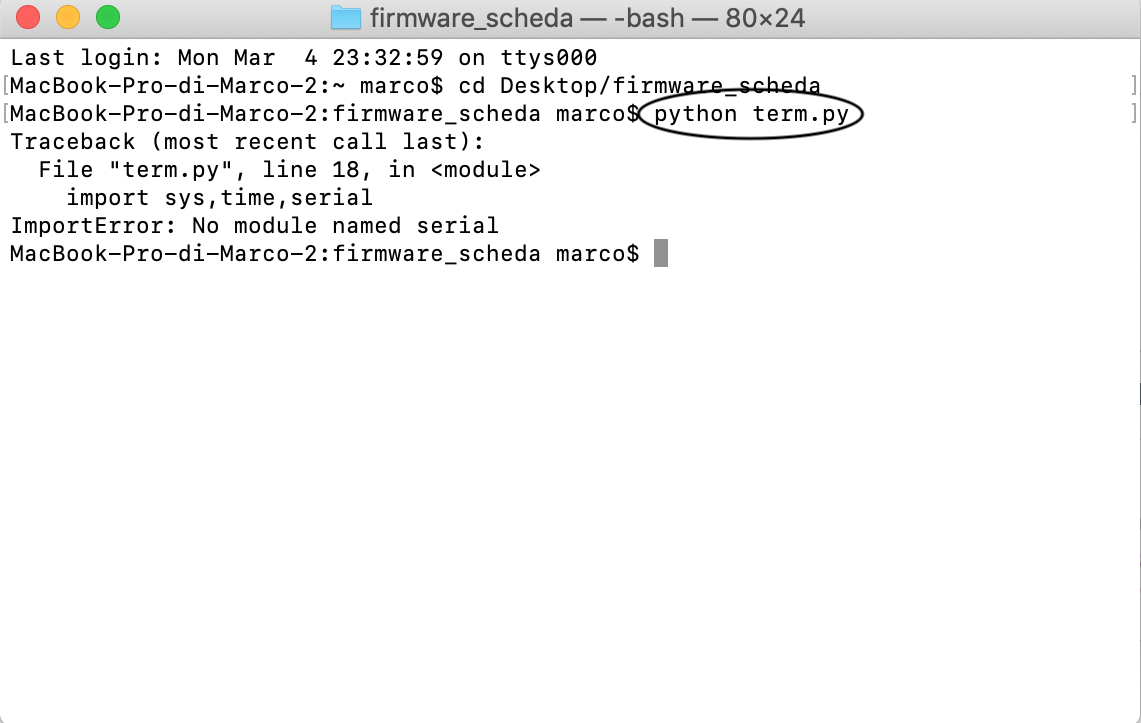
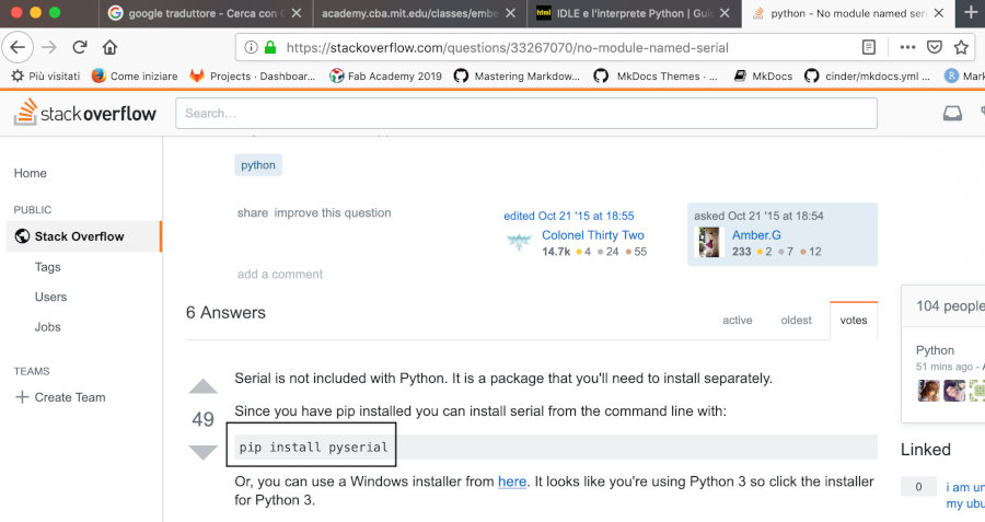
But I need to install pyserial with this command:
pip install pyserial
then I have installated a tktools with the coomand seeing in this page
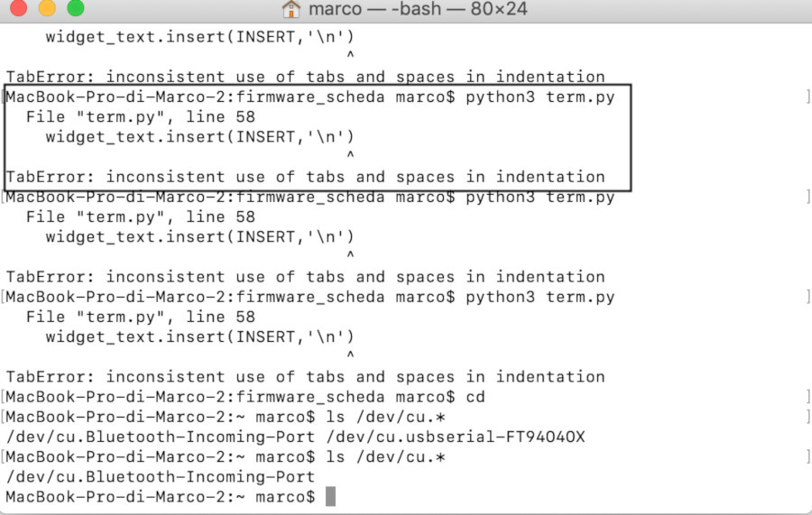
I try with this command(because I have the version python 3):
python3 term.py
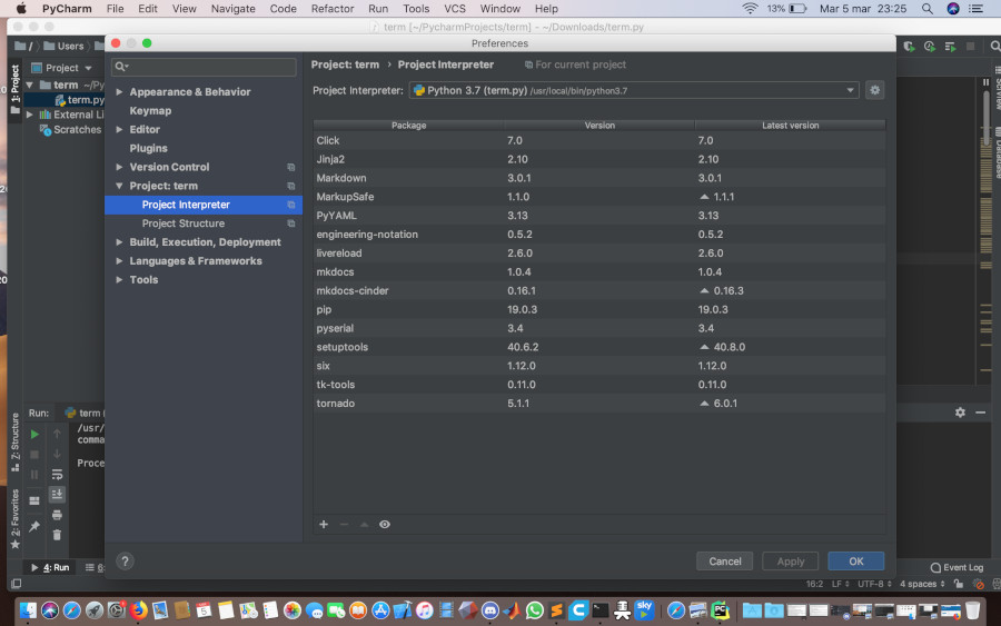
then I have the file term.py with PyCharm becuase I have had problem with the intentation of the file:
and I check if there is in the preferences the tktools installated before :
Now the script in python haven't any error and I can link my board with the serial port and launch my file term. In order to know the name of the serial port I digit this terminal command:

python3 term.py <name_serial port> <baudrate>
and I have this output:
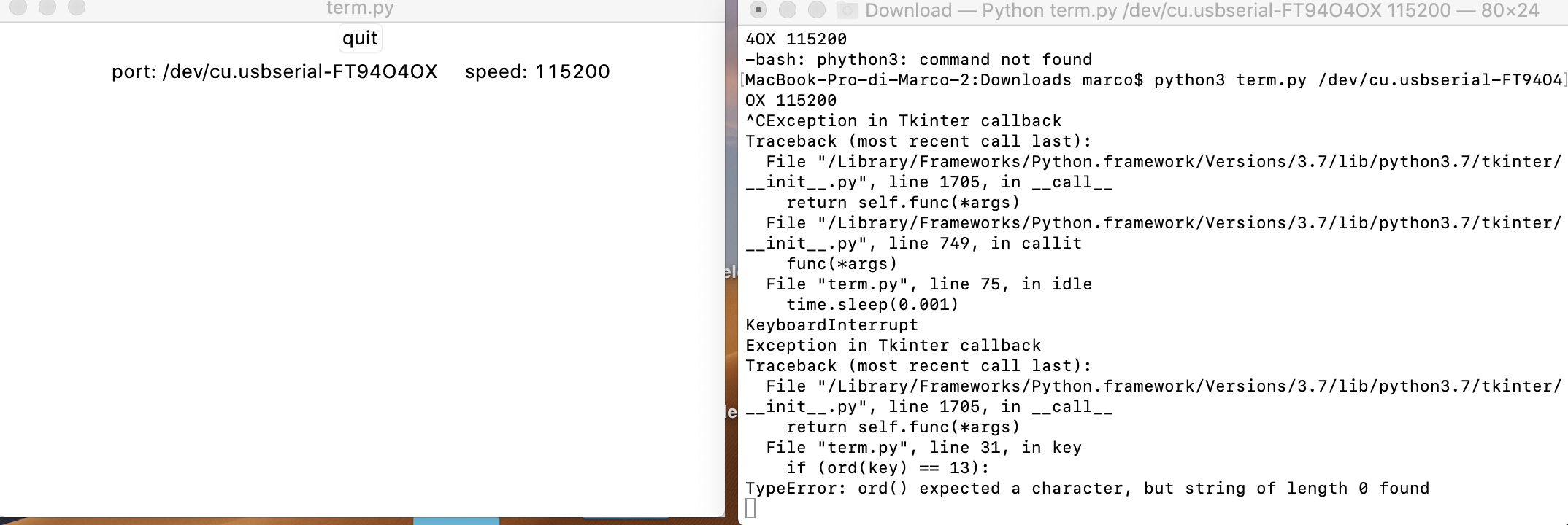
I suppose that there is a problem in the serial interface pins (probably in their solding).
In fact I haven' solded my pins correctly;
I sold again the pins better :
At the first I have launched my board with arduino and the programm work :
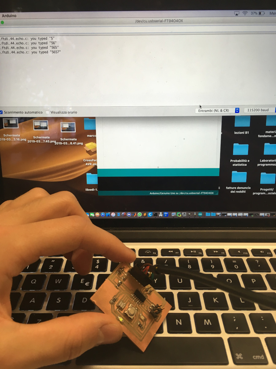
Instead with terminal command I still have problem;
Creation of the virtual environment
wheras I have correct the solding od the serial interface pin and there still are problems, I think that I have software problem(problem with python version)
so I' ve created a virtual enviroment using python2 in it and I've tried again the launching of my python file:
   virtualenv -p/usr/bin/python2.7 "name_of_environment"
   source "name_of_environment"/bin/activate
then I've installed the serial in this version of python with :
pip install pyserial
and at the end I digit the command:
python term.py <name_serial port> <baudrate>
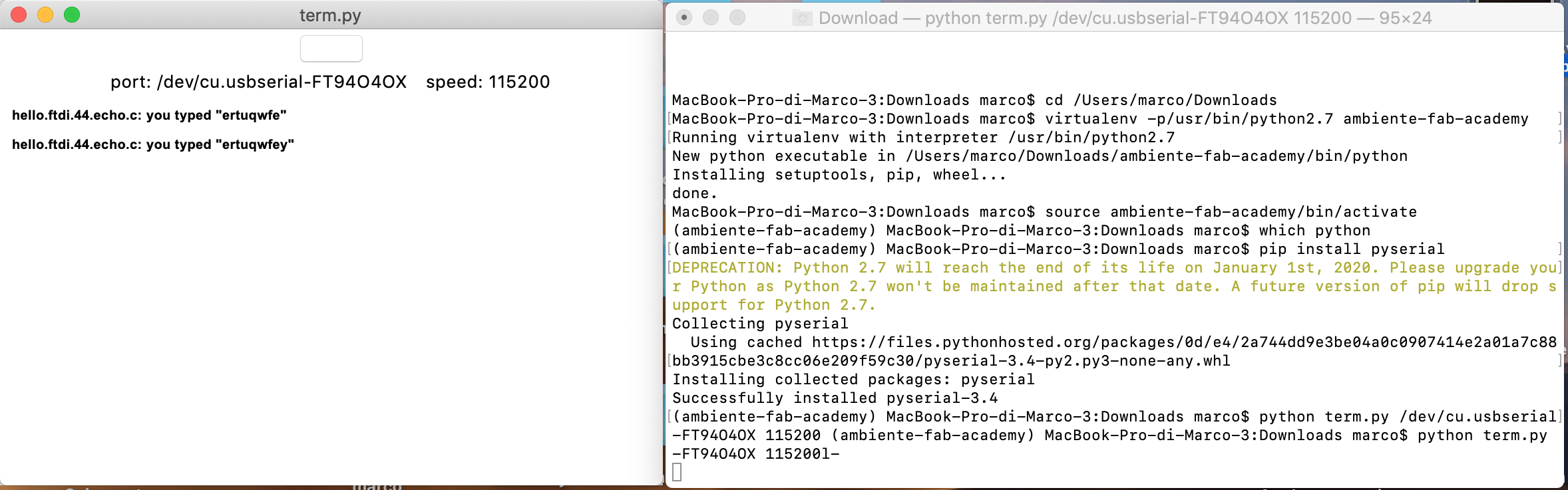
this is the output of terminal command about the creation of the environment:
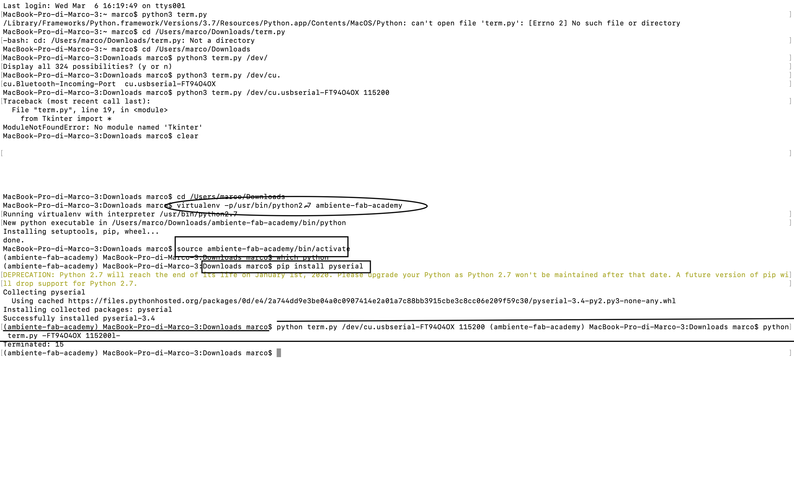
after the creation of the environment , the python file will work:
Group assignment
When I 've done my board I have linked probes on the Vcc and Gnd of my board and I 've seen the wave form generatded :
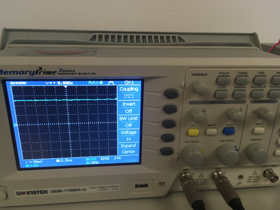
this plot shows me that the supply of my board is steadily 5v so if there aren't error in the programming the board will work(it is correctly powered). the oscilloscope shows the trend of the voltage from the two ends (vcc and ground in my case).With it we can see the voltage between the two ends of a component in order to test its working. in my case I've tested the supply of the board.
link of the week:
eagle files: