Output Device
Individual assignements
add an output device to a microcontroller board you've designed,and program it to do something
Group assignement
measure the power consumption of an output device
group work
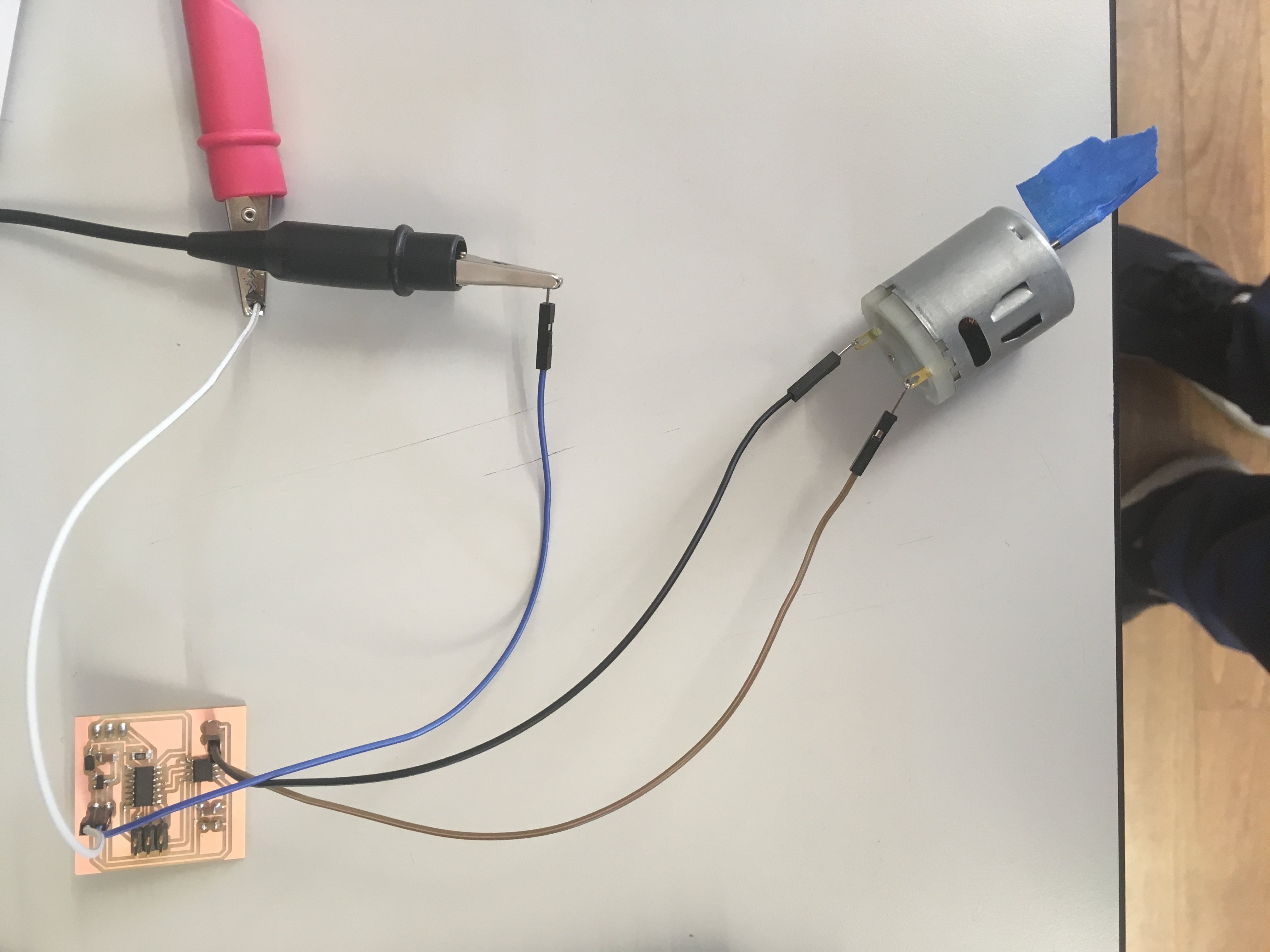
I've misured the corrent between the two ends of the motor dc when I give a voltage of 5v:
IMG_6211 from Marco Cialone on Vimeo.
the corrent misured is 0,04 A so the power is P= V * I = 0,2W
individual work
As I have done for the input device ,I've decided to do output device usefull for my final project in order to connect themselves in the networking... In fact the project that I have designed need to input device for the acquisition of the data but it also needs to output design (for exemple a lcd display) for the vision of it.
So in this week I have decided to do an lcd display and a motor dc which gives power to a fan...
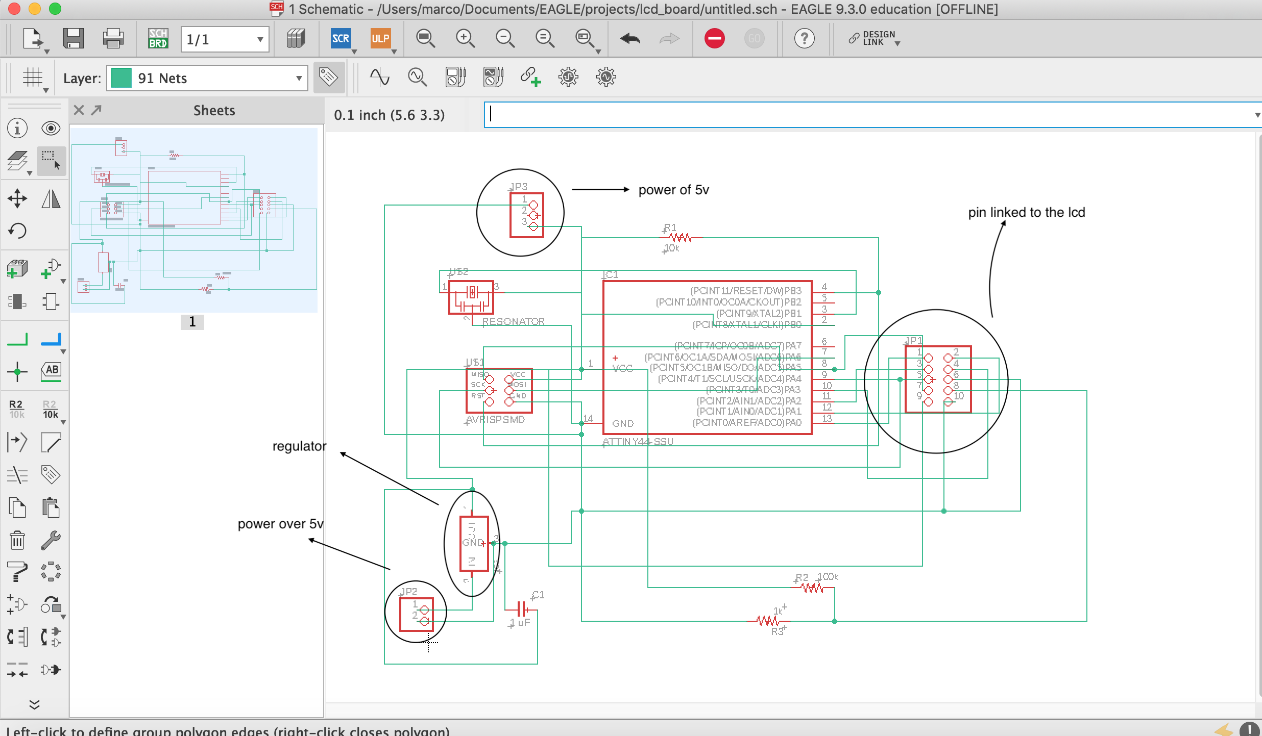
lcd board design
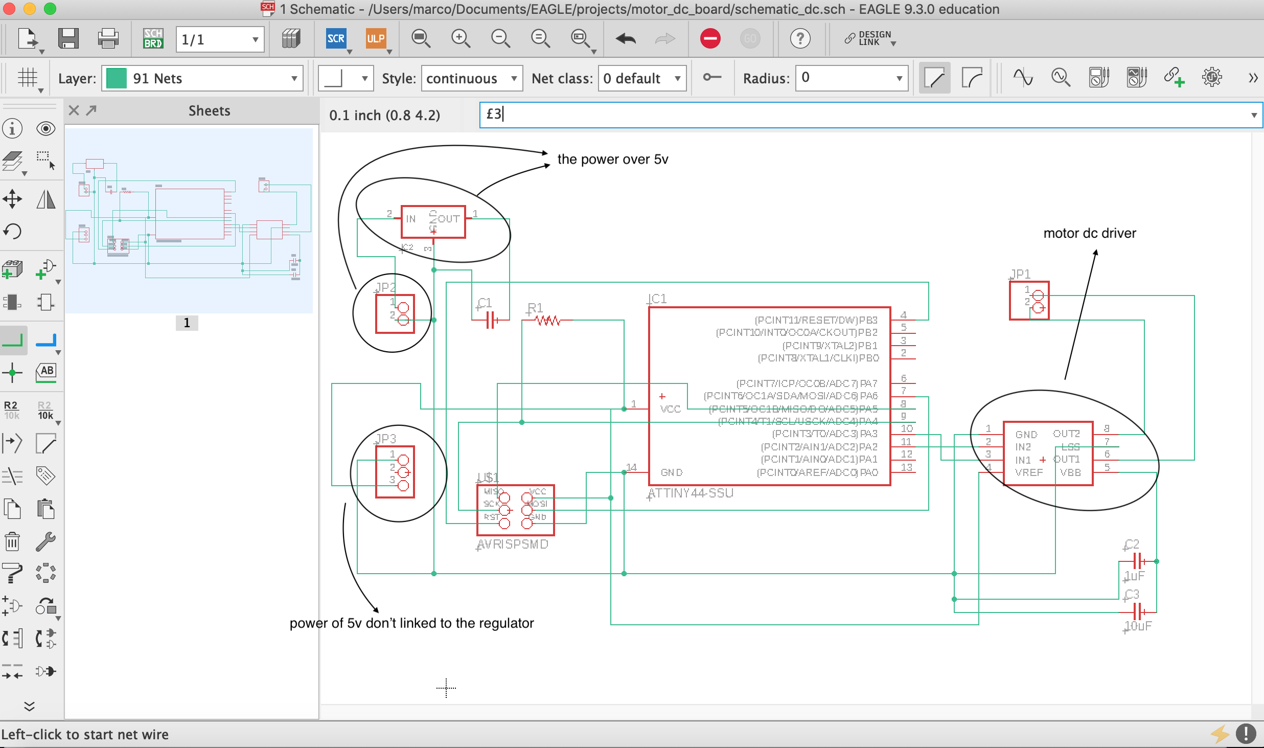
I have done the schematic and the board in eagle editing some thing than the file recommended by neil: I put a regolator which works when I use a power over 5v It adjusts the power in 5v but when I use a 5v power this regulator doesn't work. In order to solve this problem I've set two way to power the circuit; in that way if I want to power the circuit with a power higher than 5v I use the regulator and if I use a 5v power I power the circuit withput it.
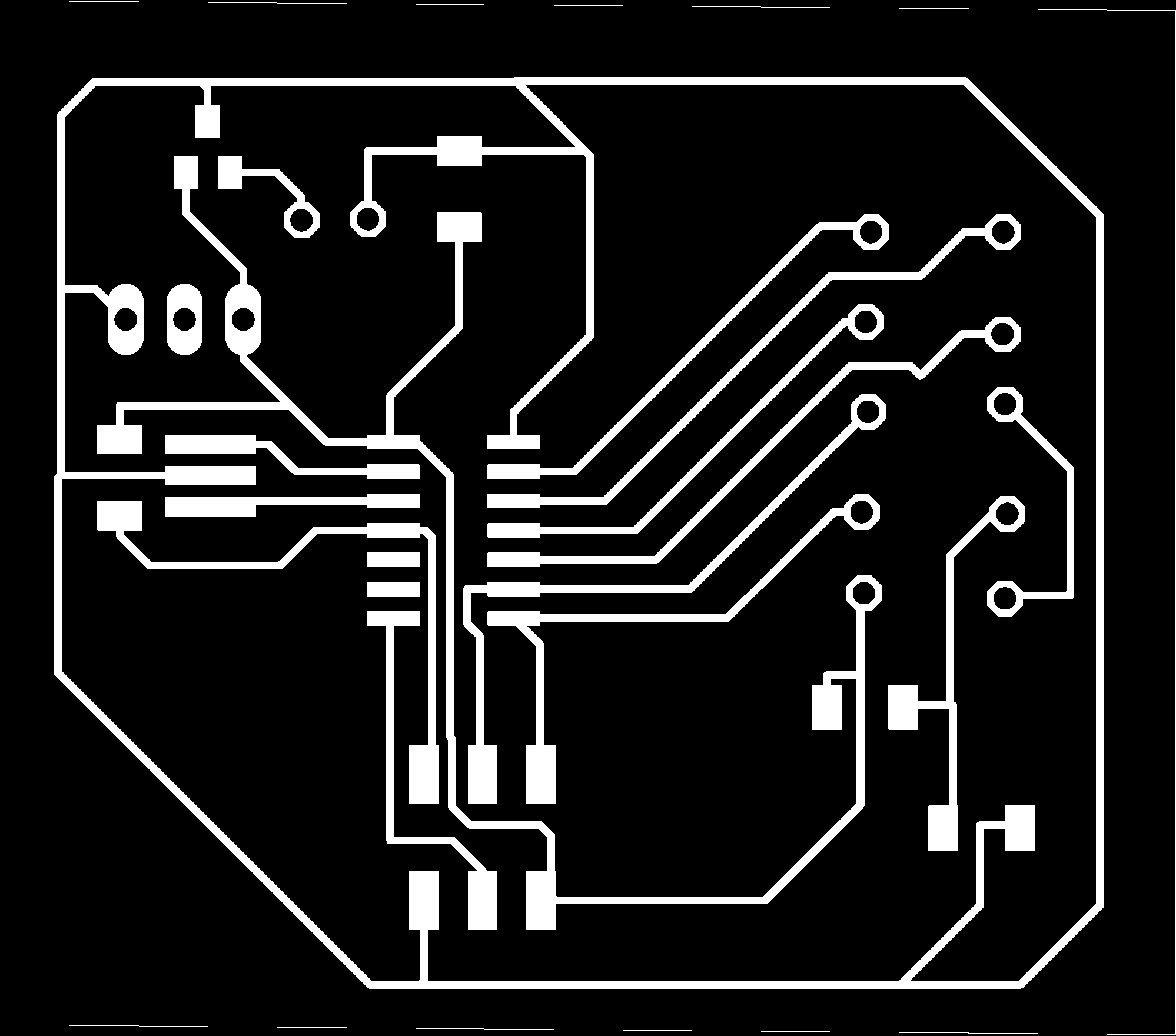
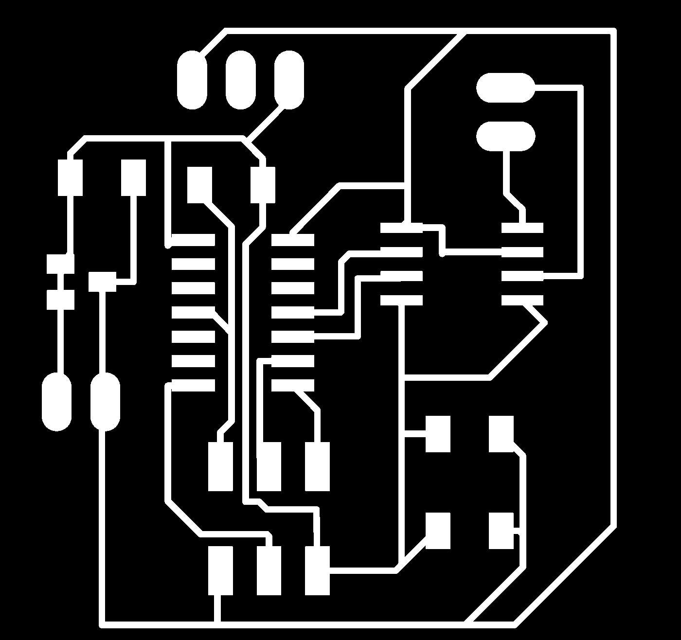
we can see the schematic and the file png of my board:
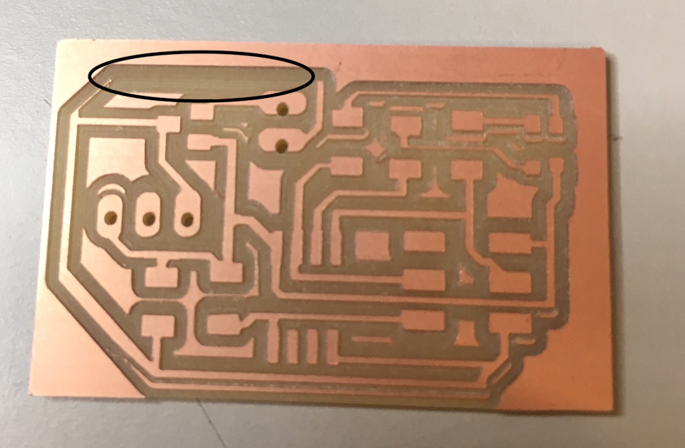
I have had problems milling this board and the led_rgb_board because the plate where I've fixed my pcb is not fixed with the axis of the machine. Before of understanding this cause of my problem I've done some milling (not good):
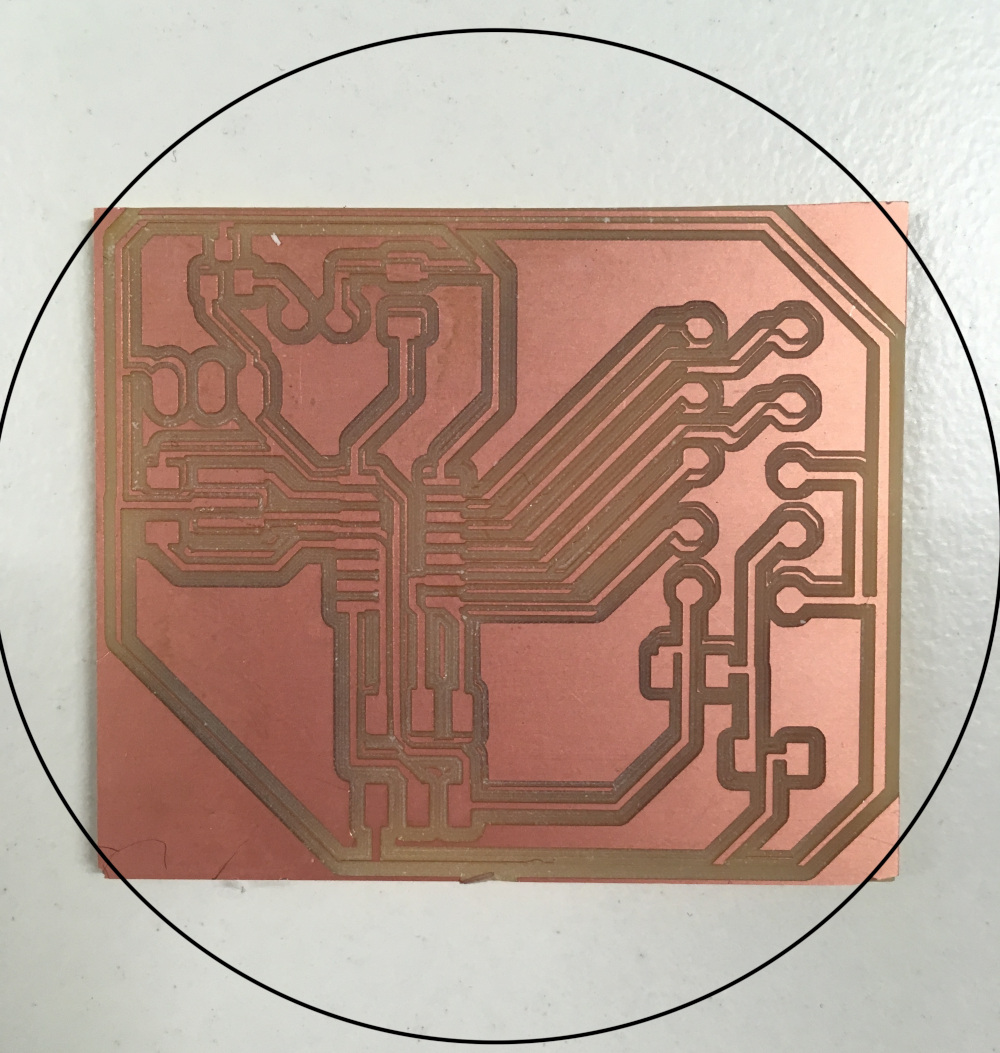
when I have solved this probelm I've milled and soldered my board but when I've tried to programm it, I find a problem in the design(toolpath problem):
my problem was here:
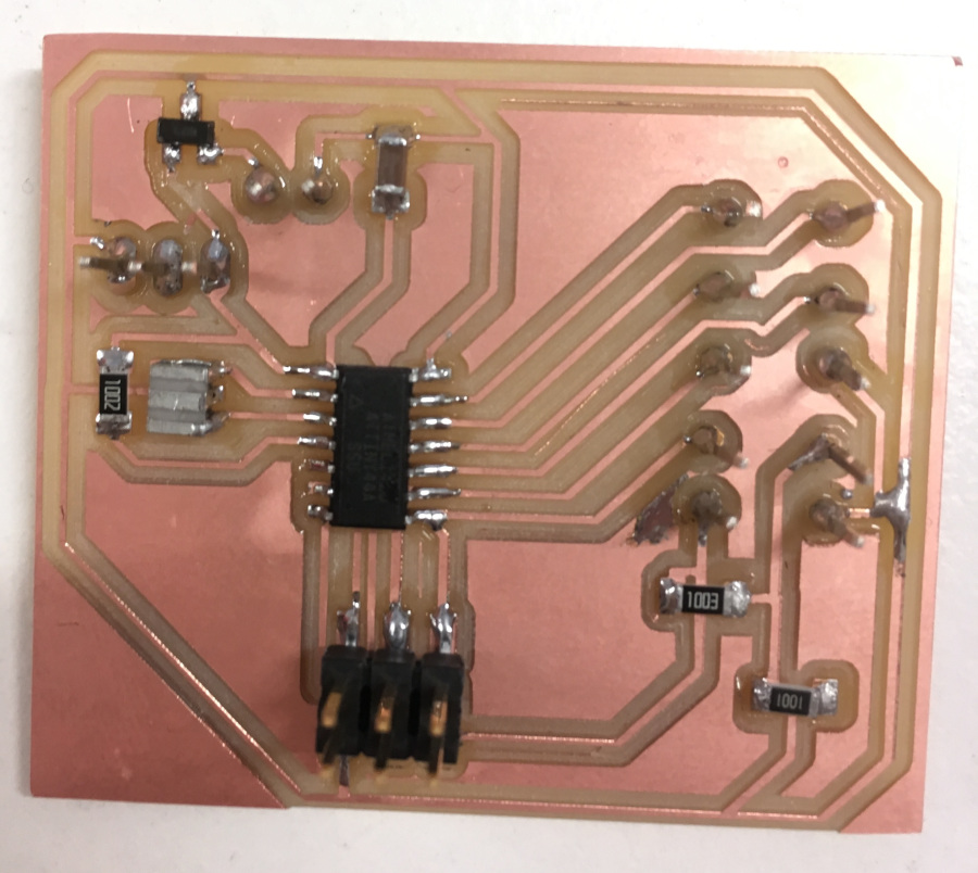
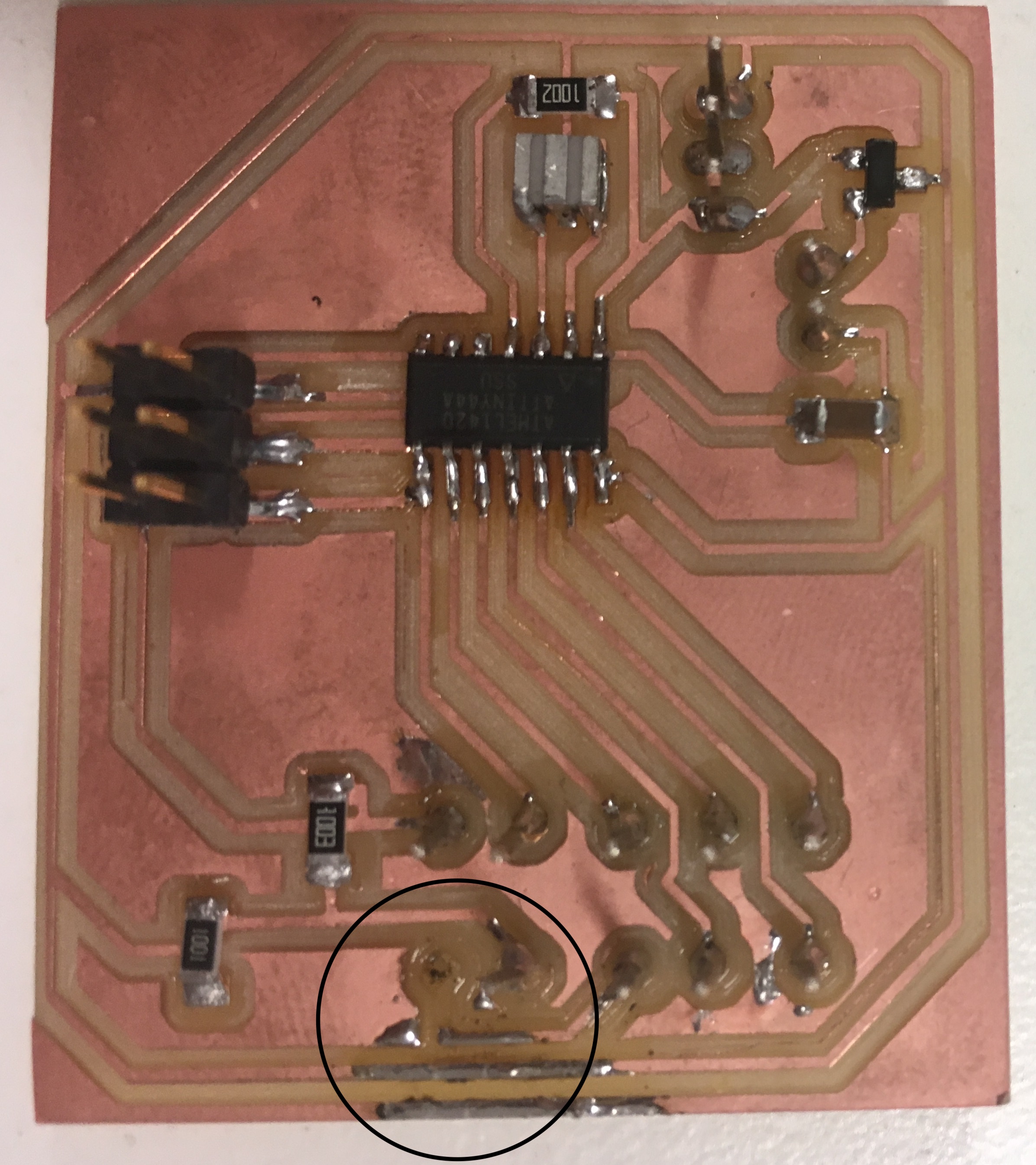
to solve this problem I've removed uncorrect short-circuit between the trace and the microcontroller's pin. I have programmed this board well but my led ldc didn't work: so I have thinked that the soldering of the header wasn't very good but soldering again I have removed copper trace so this board hadn't switched on the lcd display despite I have programmed it...
I have re-solded my board and I've programmed it with the program in c and in arduino: the program in c is similar than the neil's one but the arduino program is a bit different..
this is the lcd programmed in C:
IMG_5936 from Marco Cialone on Vimeo.
program arduino for lcd screen
This is my programmm in arduino which counts the second passed since I have switch on the lcd display:
in order to set correctly the name of the variable in my arduino lcd code I've seen the datasheet of the attiny 44:
in this link I' ve seen the corresponding name of the pin of the attiny 44,linked to my lcd screen,in the arduino programming.
| Name pin in Attiny 44 | Name pin in arduino programming |
|---|---|
| PA0 | A0 or 0 |
| PA1 | A1 or 1 |
| PA2 | A2 or 2 |
| PA3 | A3 or 3 |
| PA4 | A4 or 4 |
| PA5 | A5 or 5 |
This is my programmm in arduino which count the second passed since I have switch on the lcd display:
// include the library code:
#include <LiquidCrystal.h>
 // initialize the library by associating any needed LCD interface pin
// with the arduino pin number it is connected to
const int rs = 5, en = 4, d4 = 3, d5 =2, d6 = 1, d7 = 0;
LiquidCrystal lcd(rs, en, d4, d5, d6, d7);
void setup() {
// set up the LCD's number of columns and rows:
lcd.begin(16, 2);
// Print a message to the LCD.
lcd.print("hello, world!");
}
void loop() {
// set the cursor to column 0, line 1
// (note: line 1 is the second row, since counting begins with 0):
lcd.setCursor(0, 1);
// print the number of seconds since reset:
lcd.print(millis() / 1000);
}
IMG_5942 from Marco Cialone on Vimeo.
motor dc board design
I 've done the dc motor board with the same idea of the lcd one: I put two option od power separated and I put the output for my motor linked to the driver of it.
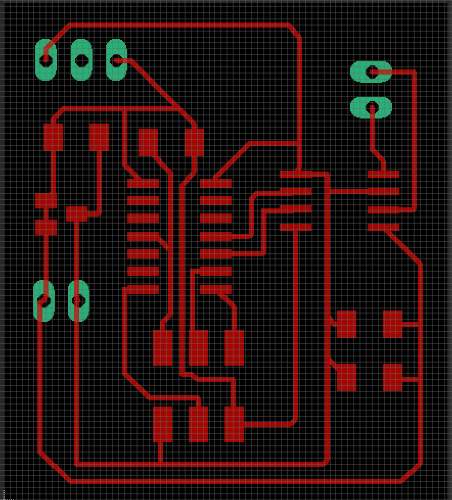
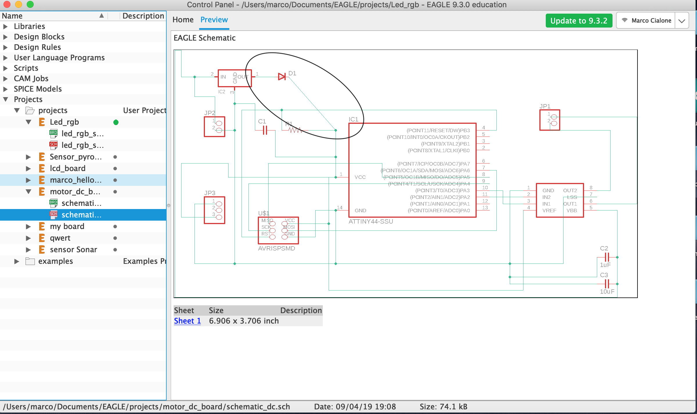
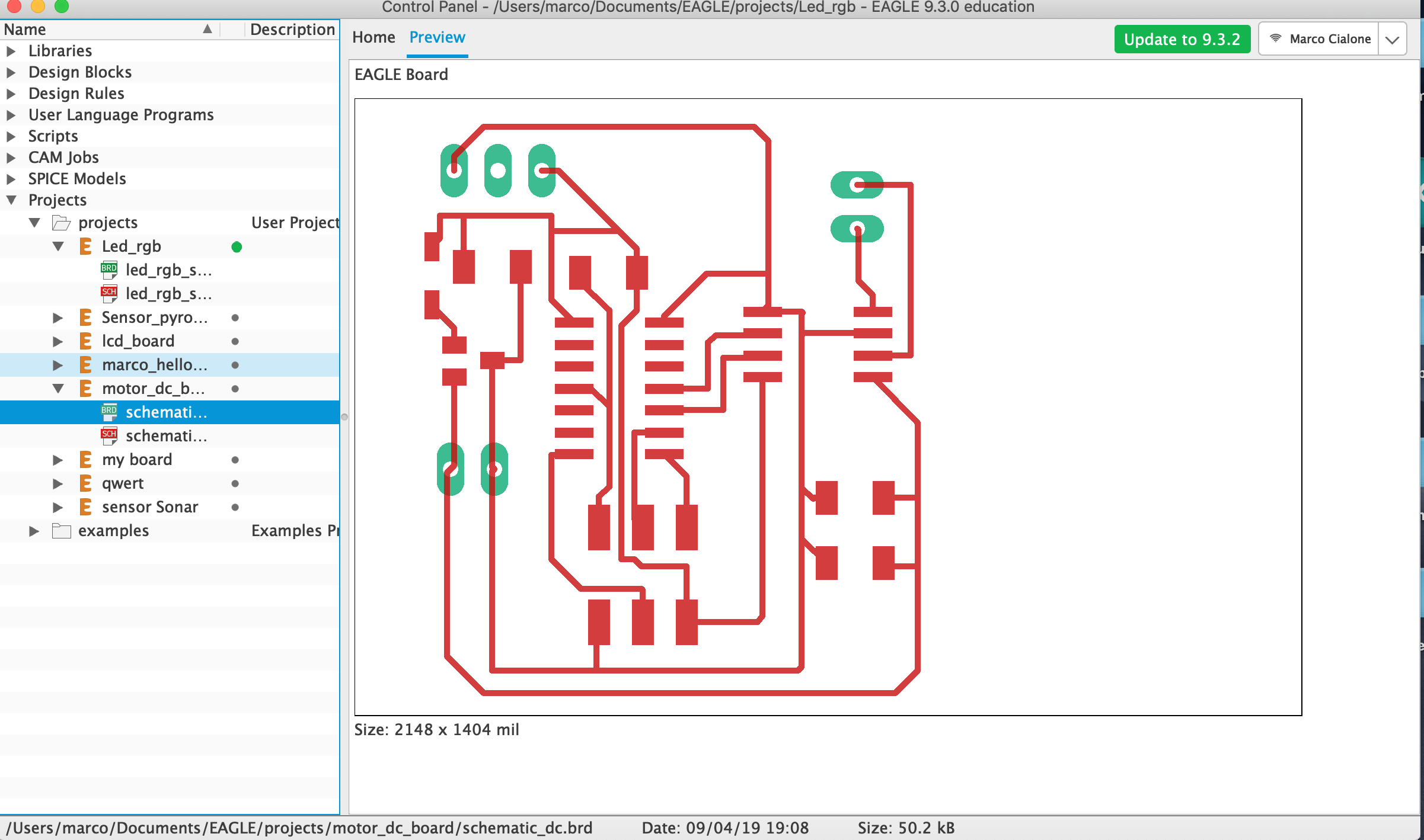
we can see the schematic and board for the motor board too:
I have done a mistake because I have linked the Vbb of the driver motor with the Vref and Vcc(5v).. but seeing the datasheet I've seen that the driver want to have a voltage at least 9v.. and when I was programming my circuit the voltage regolator warms a lot.
To solve this problem I've tried to put a diode linked to the output of my regulator in order to reject the corrent in the out of my regulator when I am programming or power my circuit with 5v.
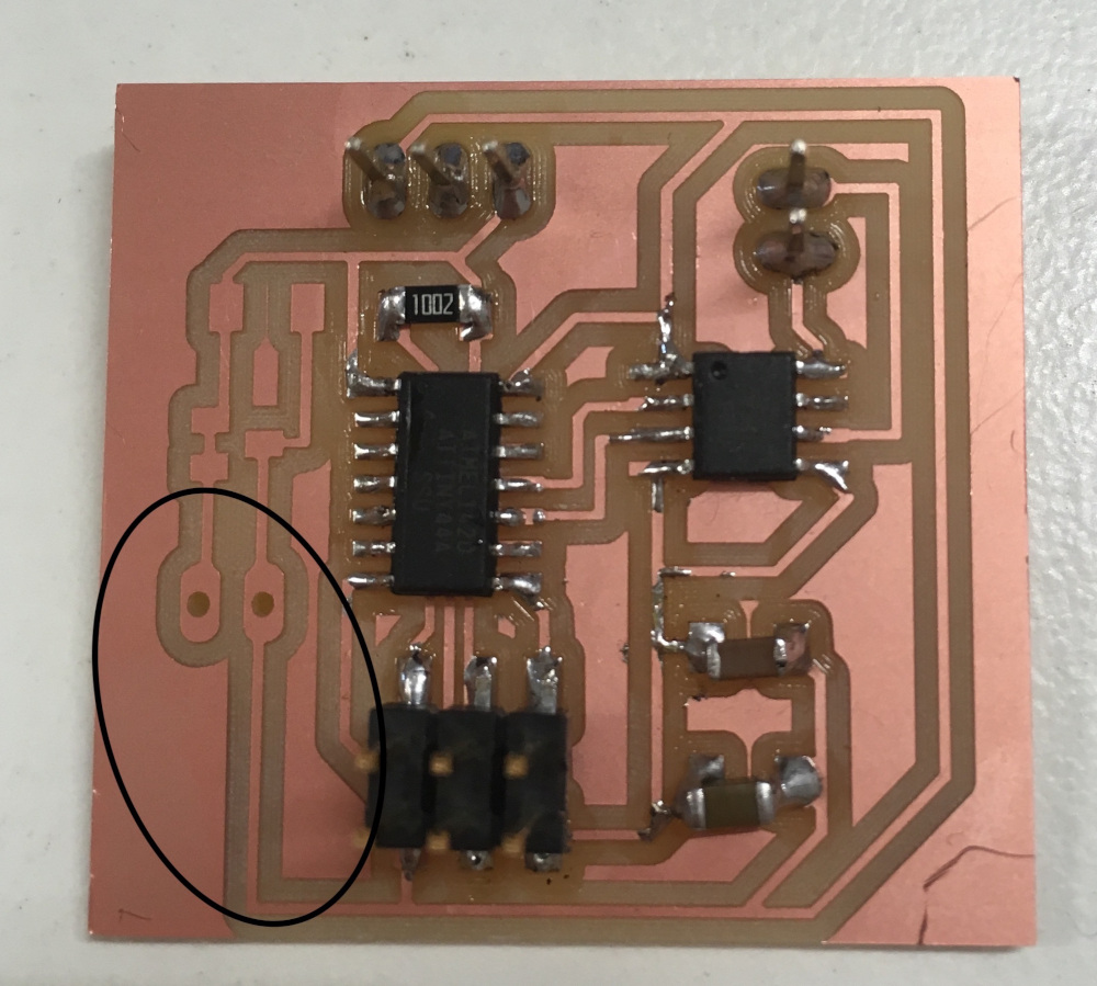
and my final board is this:
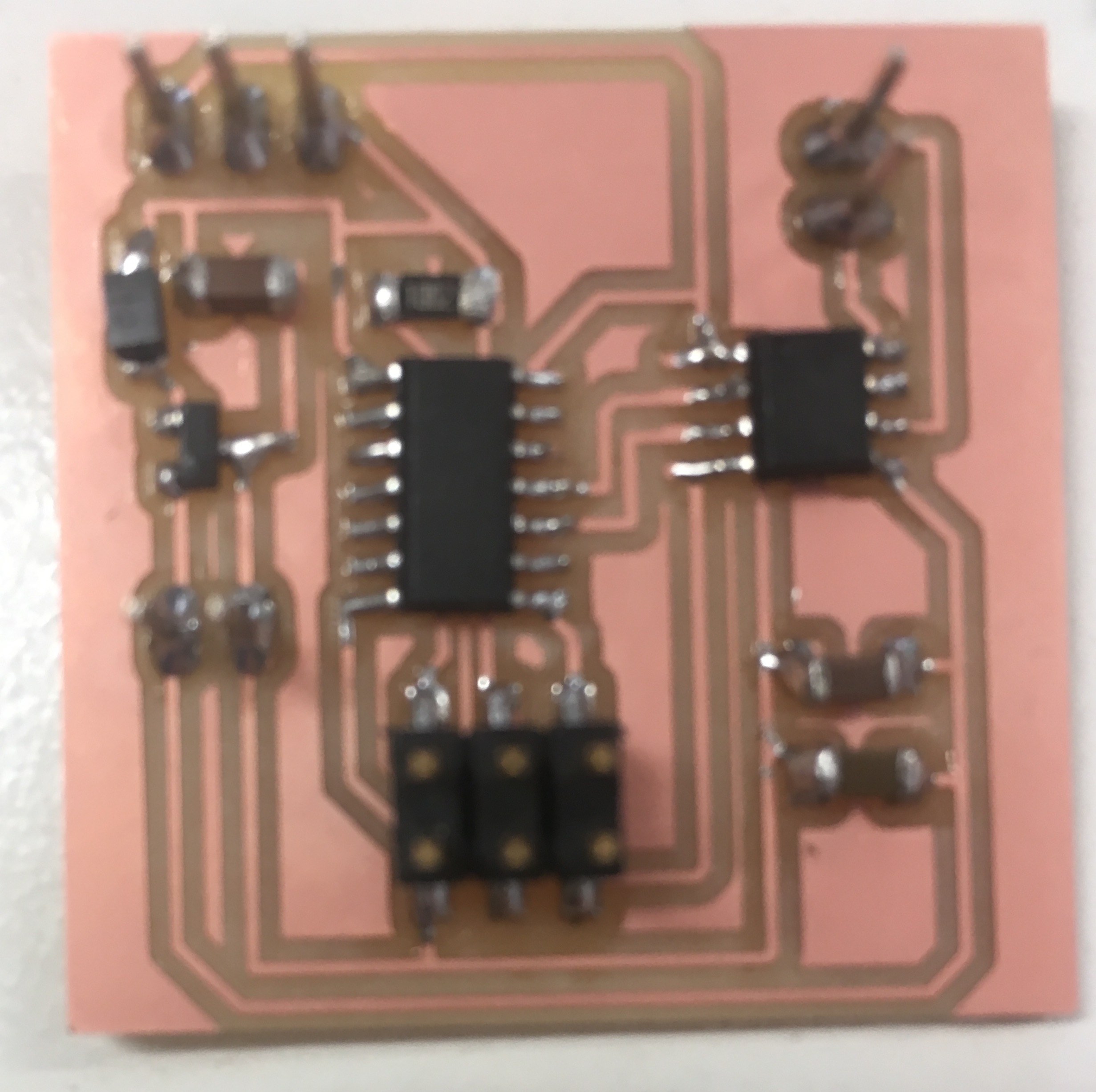
I tried to power the circuit with a bench power supply:
and it works
IMG_5952 from Marco Cialone on Vimeo.
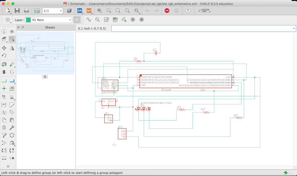
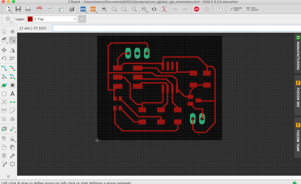
led_rgb design
I've wanted to do a led_rgb because it can be a possible usefull output for my final project:
I haven't linked the miso to its microcontroller pin;so to solve this problem I've done a bridge and the board work well:
IMG_5918 from Marco Cialone on Vimeo.
but in order to have a correct design project I've corrected the schematic and board file in eagle linking the miso to the microcontroller: