Electronics production
Group assignement:
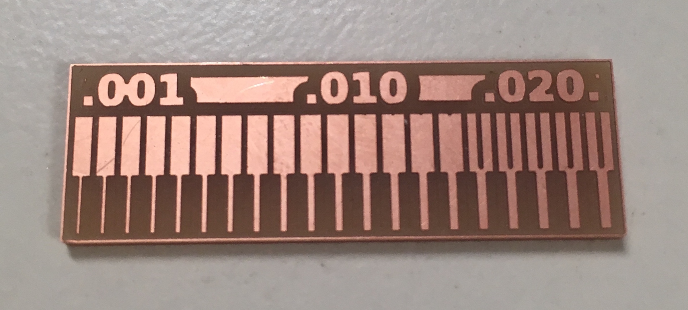
characterize the design rules for your PCB production process
Individual assignement:
make an in-circuit programmer by milling the PCB,program it, then optionally try other PCB processes
Process to make a circuit:
In this week I have to produce a PCB and programm it. I have to choose a circuit already designed , save on my pc the file png of my trace and outline and to some step in order to make the milling.
Creation file rlm:
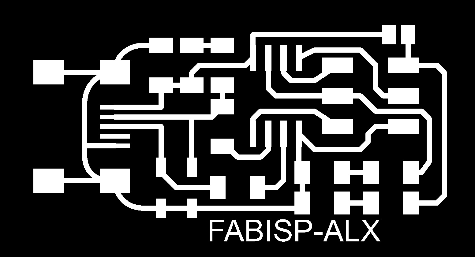
First of all, I' ve chosen the alex design circuit on the site of fabacademy
so I've downloaded the file jpg of the trace and of the outline:
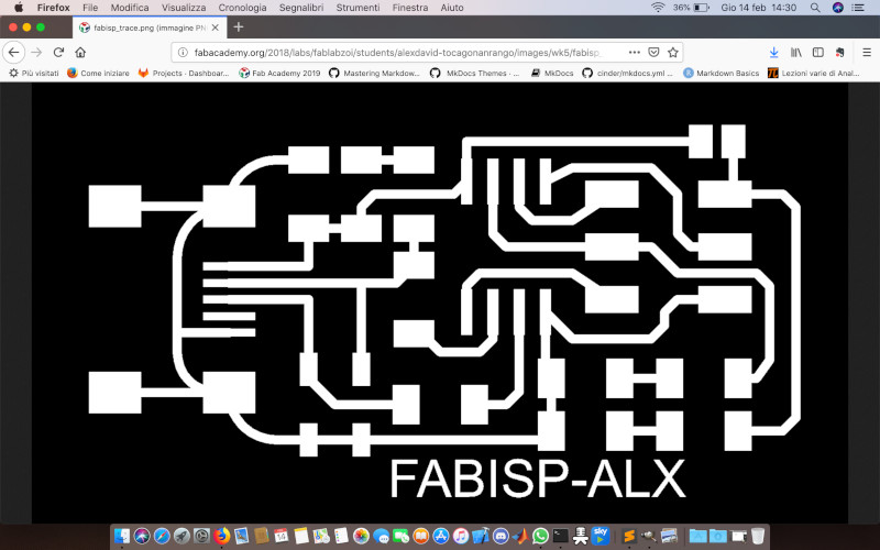
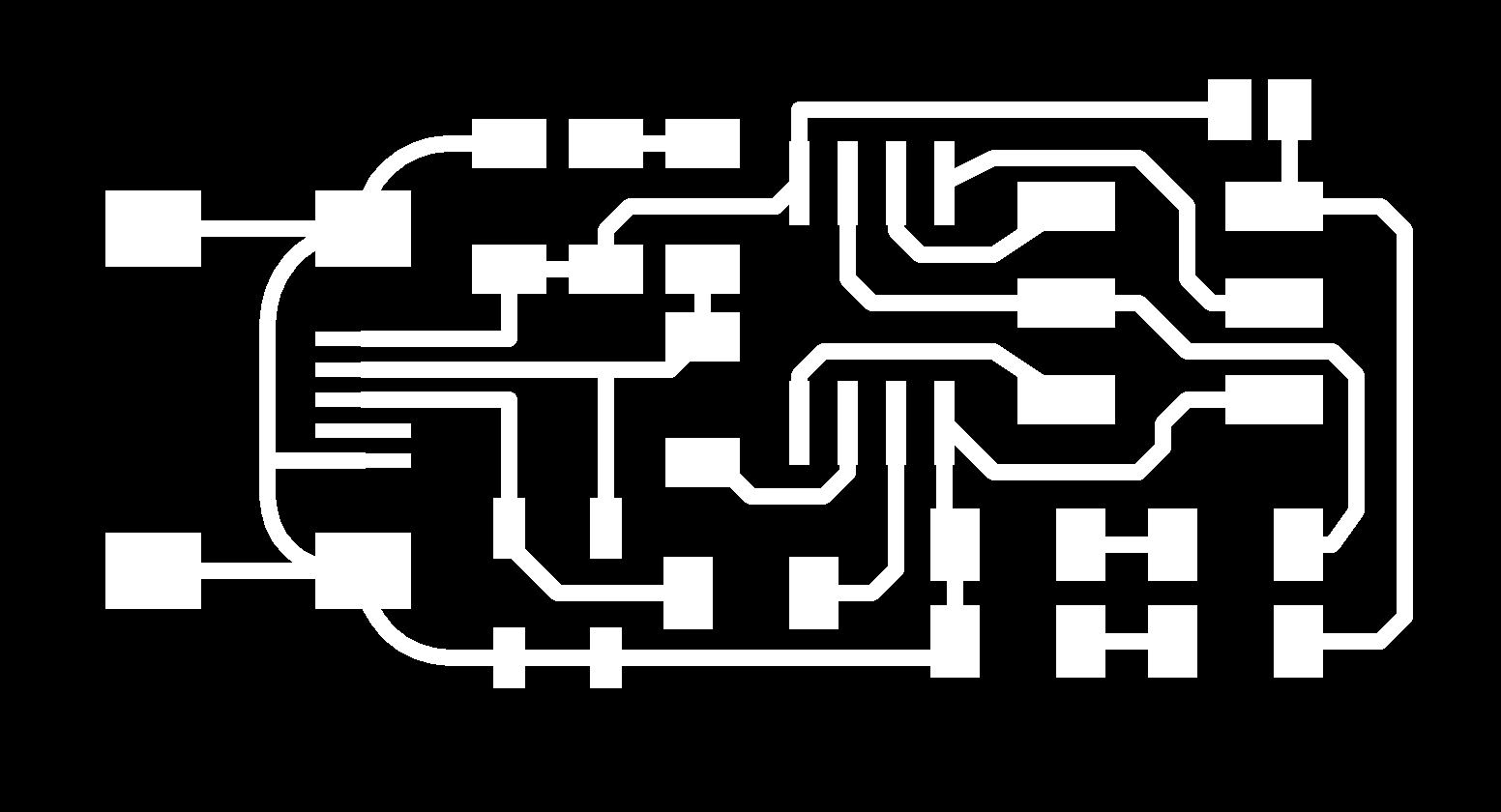
I've also modified the image removing the written but keeping the size:

I' ve used these file on the fabmodules in order to create my file rlm:
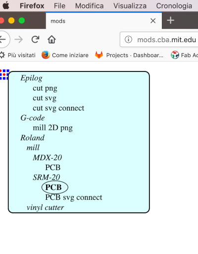
1) Program--> Open server program --> Machines --> Roland --> mill -->SRM-20 --> PCB
2)
I've delete the web-socket-device
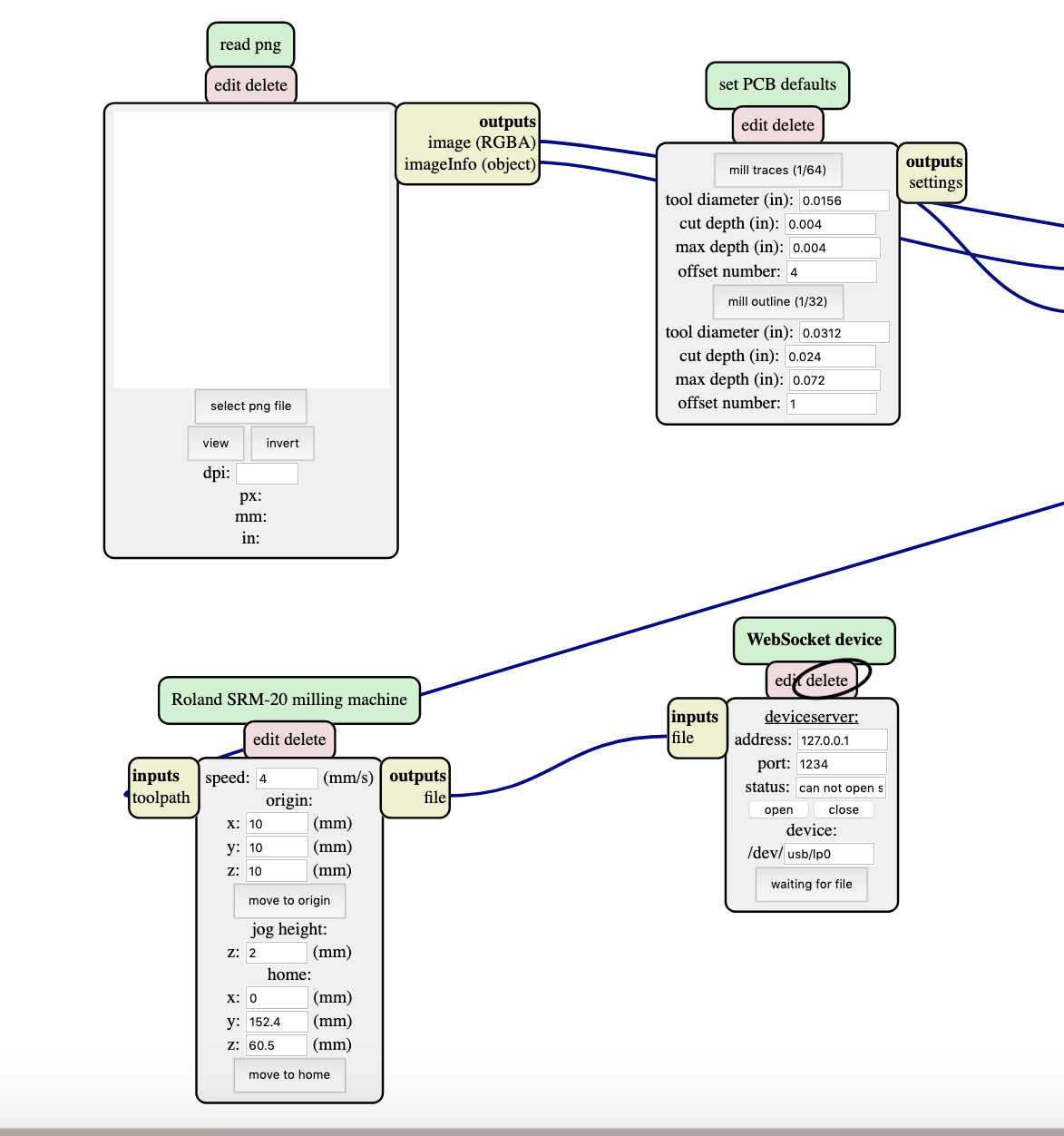
3) I clicked the right mouse button and I chose :
Module --> open server module ---> FILE --> SAVE
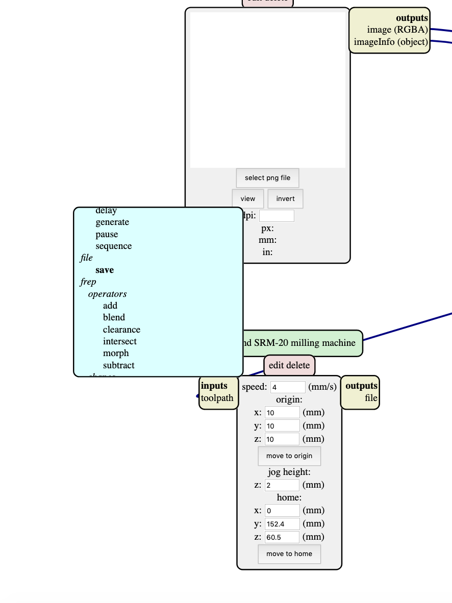
This is the moduel "save" generated:
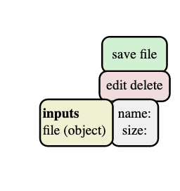
4) finally I link the output file with the input file of the module "save"
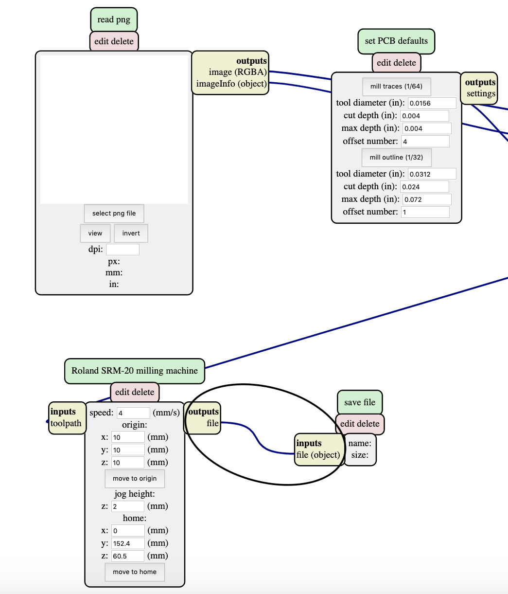
Trace rlm
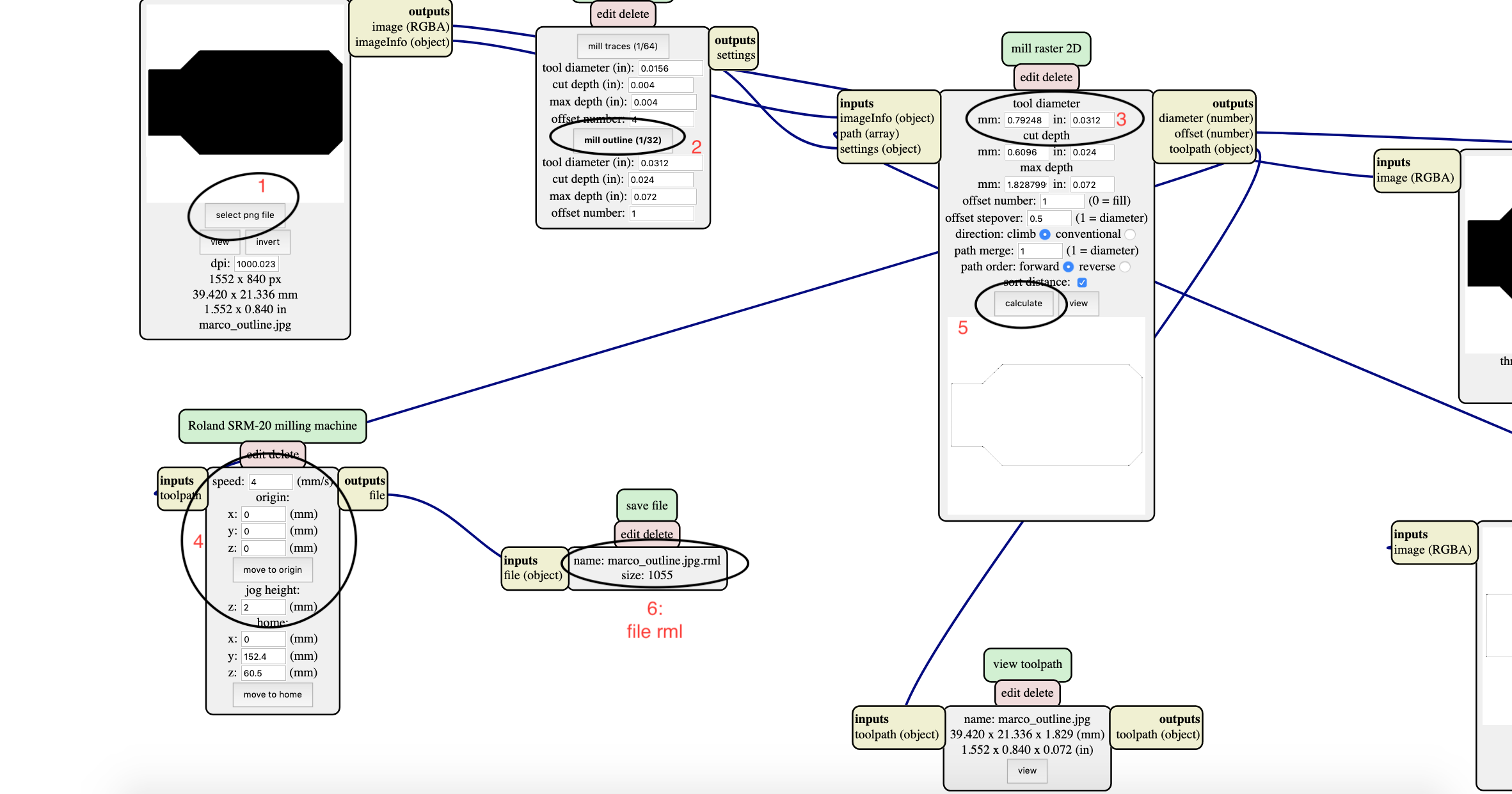
1) I open the trace file png
2) I set the tool diameter(usually we have to use the default tool diameter clicking mill traces)
3) I set the origin and maintain the speed and the jog height
4) click on "calculate"
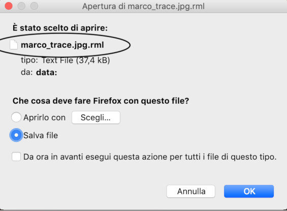
5) finally, we have our file trace.rlm ready for the use.
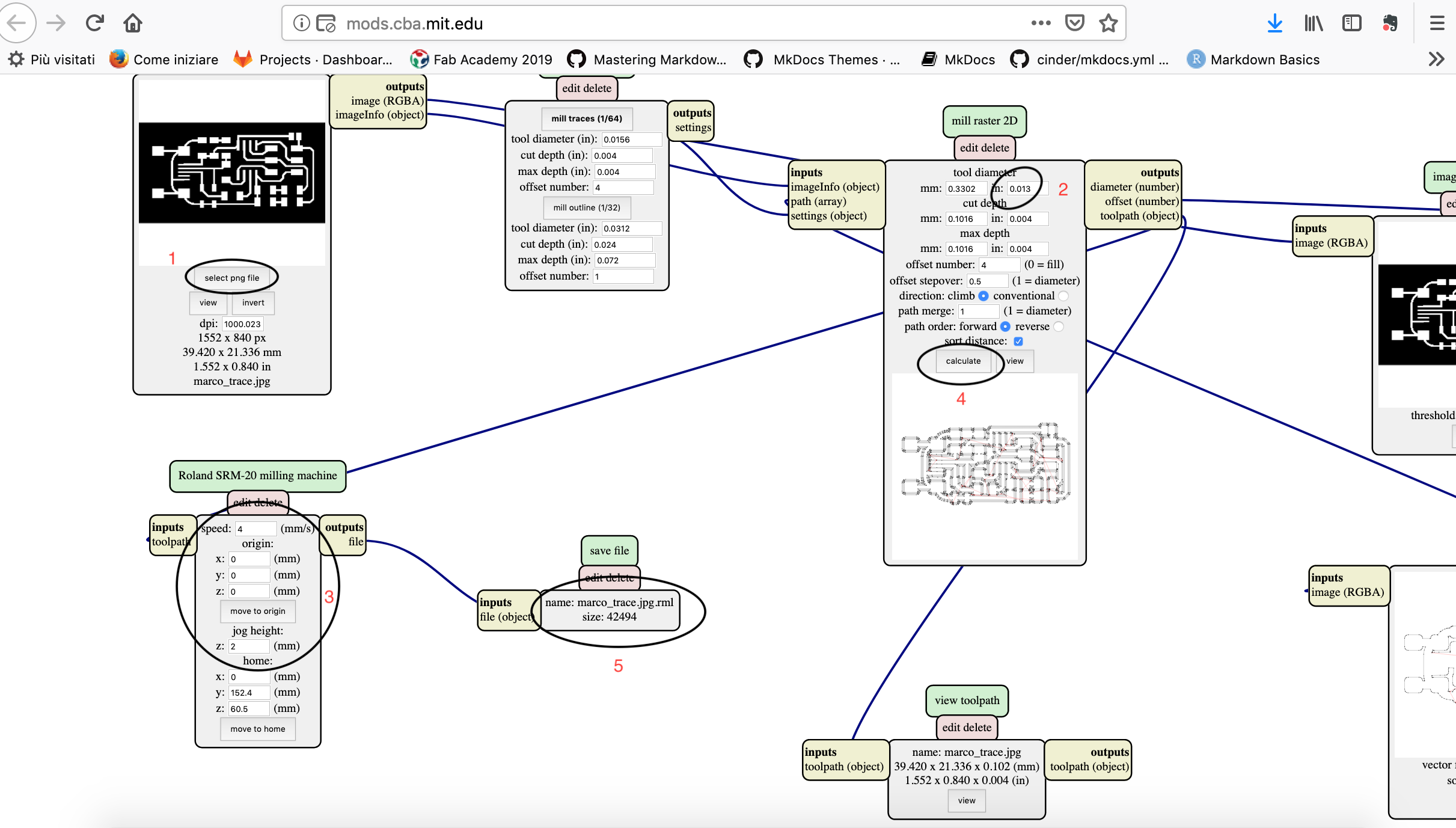
- we can see the different between the setting of default value mill trace and my setting edited. We can see that with the default menu I haven't a main trace. the reason why is happened is that the distance between a line and next one is smaller than the diameter lenght so the programm isn't able to do it. I solve the problem changing the parameter of the diameter in order to make it smaller than the distance of the lines. In that way , the programm is able to make the line : in this different, view we can see the two file rlm(language's machine)


Outline rlm
1)I open the outline file png
2)I set the mill outline(is the default setting for the outline)
3) we can see the value set in "mill outline"
4) I set the origin , maintaining the speed and the jog height
5) click on "calculate"
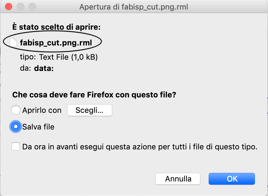
6)Finally , we have our file outline.rlm ready for the use.
Mistake in the milling
In the fase of preparation of the file .rlm I have done a mistake. Because of my trace png file have a written, I've deleted with gimp:
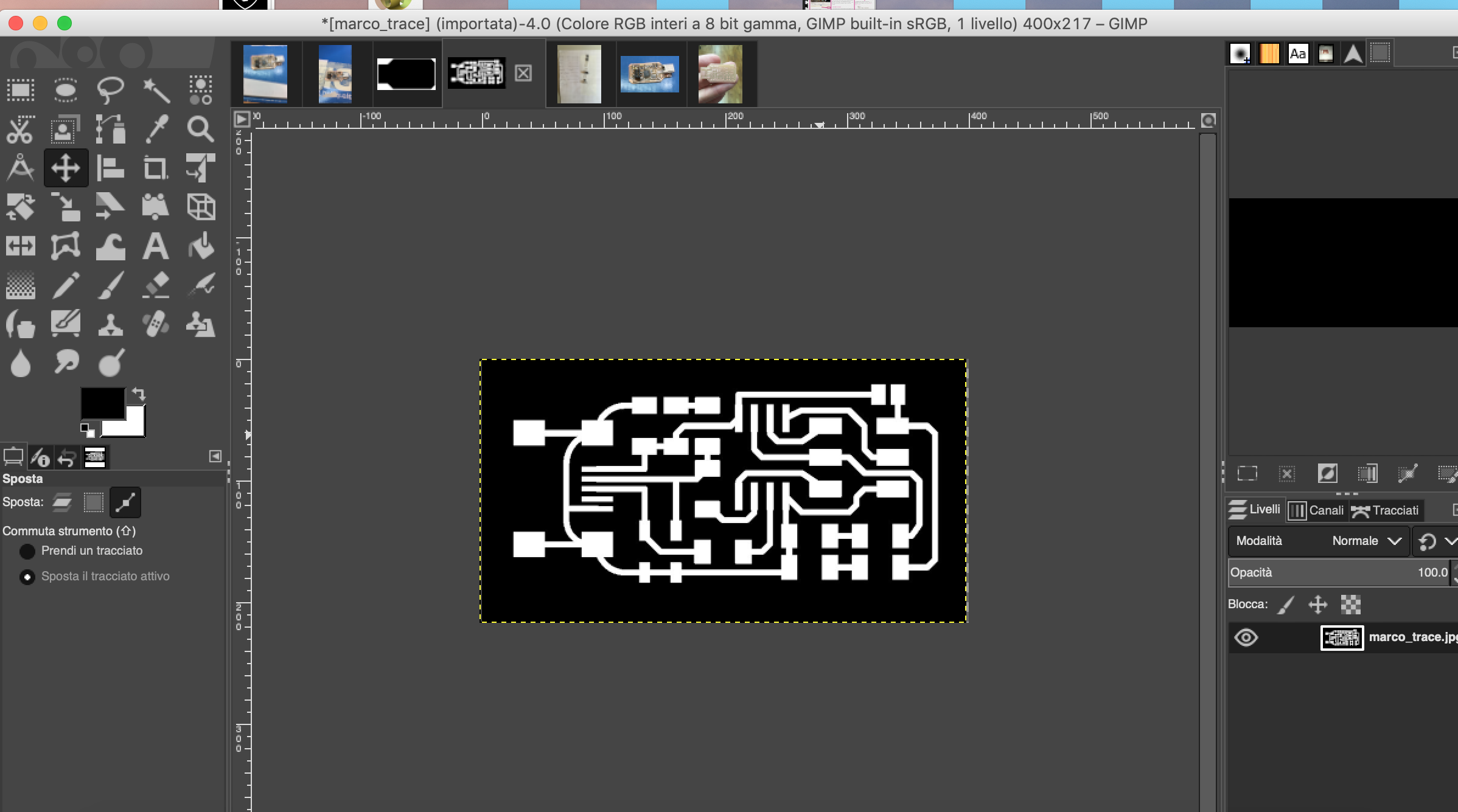
but I forgot to mantain the same size of my original file trace so the file trace and the outline one haven't the same dimension and in the milling process , the outline is made over the trace:
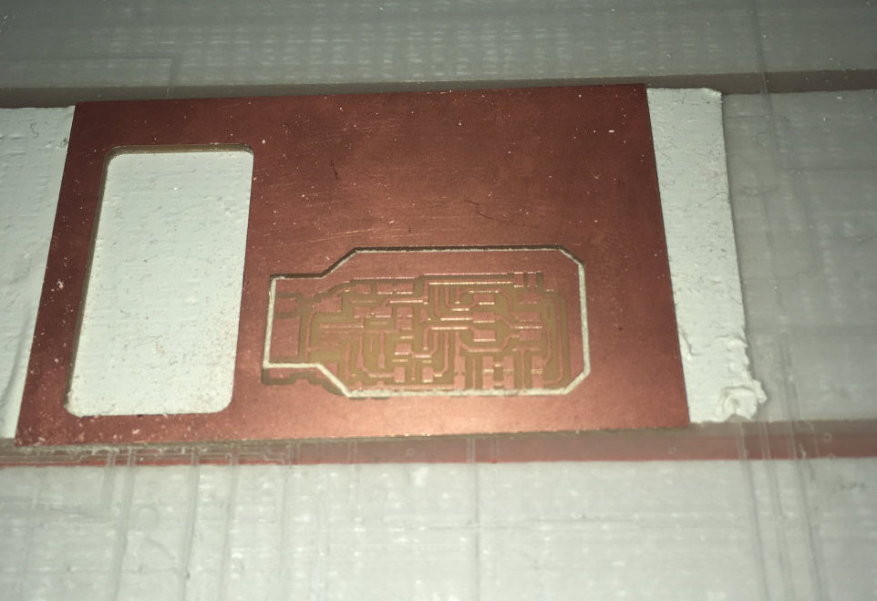
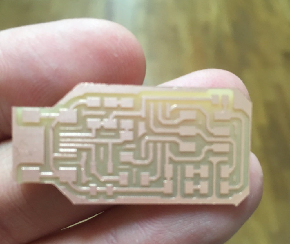
So I have remake my file png deleting the written but maintaining the size of the original file. With the correct size of the trace and outline, I manage to do my milling with the outline at the border of the trace:
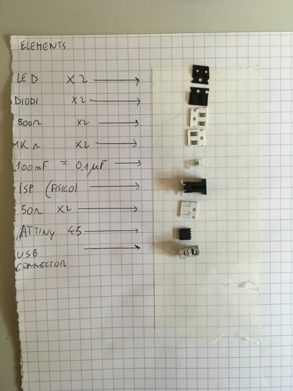
Bill of material
the bill material is a simple list of the component I need to soldering on my pcb:
- led (2x)
- diodes 3.3 (2x)
- 500 Ohm resistor (2x)
- 1k Ohm resistors (2x)
- 100 nF = 0.1 uF capacitor
- ISP
- 50 Ohm resistor (2x)
- ATtiny 45 (MCU)
- USB connector
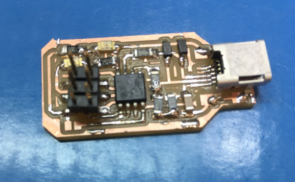
Soldering
This is a particulary step of the building of the PCB circuit. In this lavoration if you do a bad mistake the programmer don't manage to work on your programmi so you have to restart the milling too. I enjoy a lot the soldering and ,despite the component are very small and the soldering take me much time , at the end I 've liked my work.
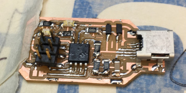
I hope that in its programmaing, there won't be any problems.
Programming
After the solding I have only to program in order to check that my pcb circuit works. I 've followed a tutorial of Alex in the fab academy page.
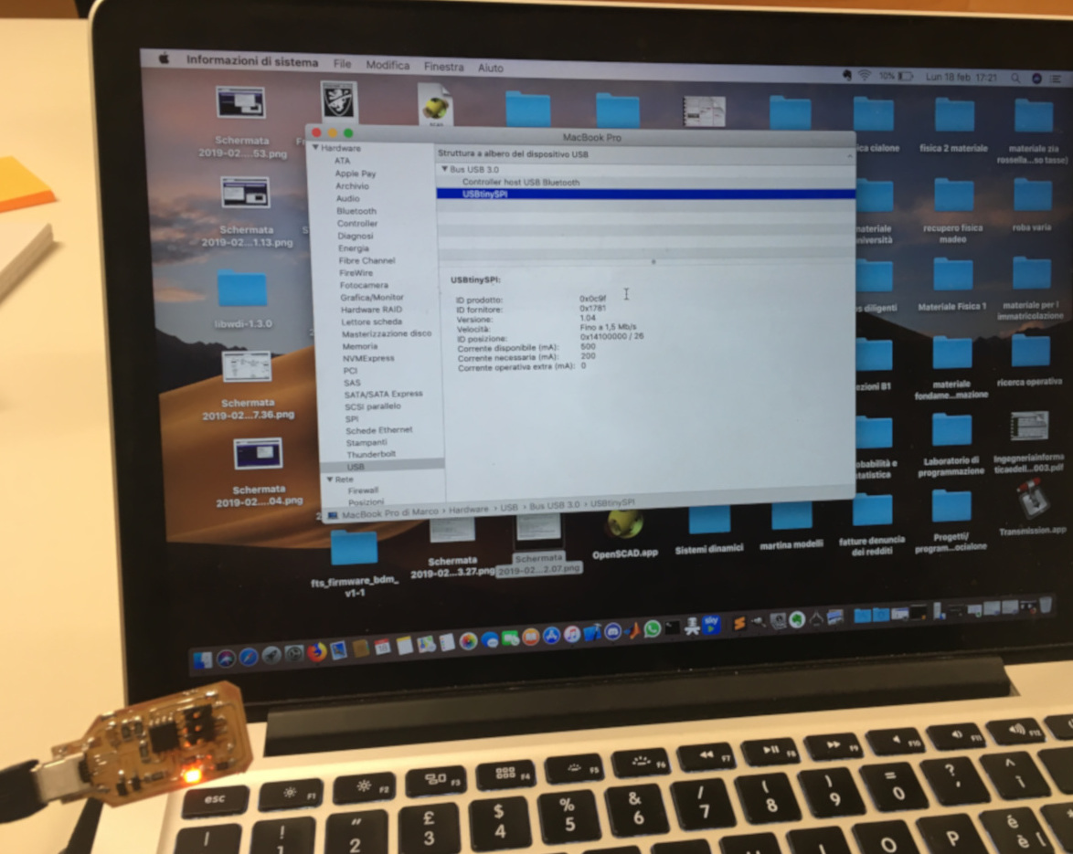
First all, I've connected only the programmer on my pc and
I going on:
information on this mac->view ->report system -> hardware ->usb
and I see: FabISP device
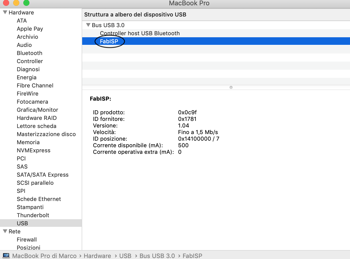
It means that my programmer still work.
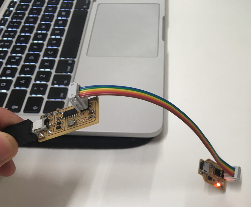
so then I've linked my programmee to the fabisp and the its led light itself so I probably haven't any problem in the soldering of component linked to the led.
In this moment I start the programming:
- Install CrossPack
-
Installing CrossPack and already having Xcode, I have had GNU Make too.
-
we move on firmware directory by using command cd/path-of-the-firmware/
- we check if we have installeted correcty avrdude and gnu make with this command:
$ avrdude -v

$ make -v

$ avr-gcc --version
This is an important command terminal:
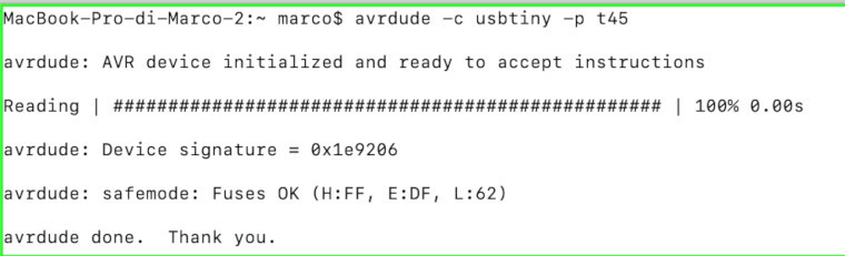
$ avrdude -c usbtiny -p t45
My error output:
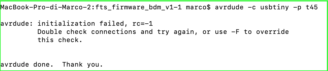
The error was in the hardware of the circuit:
I solve this problem removing a short circuit that has created the error.
And the final output is this :
then I digit this coomand :
 $ make flash


 $ make fuse


 $ make rstdisbl
with all this command at the end I have programmed my fabisp.
Design rule(group assignement)
I take files traces and outline from page fab academy "electronic production". I prepare file rlm with fabmodules using png files trace and outline.
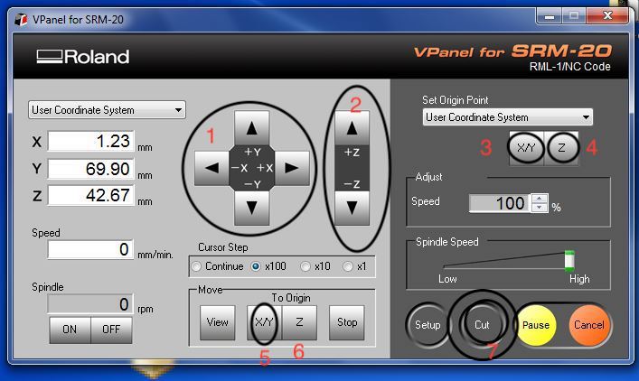
In the software of the milling machine :
1-3)I set the x,y position moving in the part where I want to use for origin.
2-4)When I've set my origin x/y I move the machine on z axis until the tip touch
5) when I want to go on the position of my origin I click on the button X/Y.
6) when I want to go on the Z origin I click on the button Z.
7) I click on "cut" to select the file trace and interior(rlm)to launch on the milling machine
When I mill my trace and my outline, I have the rule for my PCB production process.
Working Files:
The file of my design rule:
The file of my PCB are:
The firmware for my programming :
The fabmodules link: