9. Embedded programming
What I learned on this week
On this week, I learned
- Some detailed specifications of Attiny44
- How to make programs on my original board
Group assignmnet
For the summary of our group assignment on this week, please see this link.
Individual assignment
On this week, the individual assignments were
(1) Read a microcontroller data sheet
(2) Program your board that had been created on week7 to do something
For the second assignment, I decided to make the LED for below cases
- Blinking for 1 s(1000ms)
- Blinking When the button is pressed
- Blinking the same number of times as one I inputted by keyboard.
Blinking a LED for 1 s(1000ms)
Before programming, I checked the pin assignments on my board. The LED was connected to PB2 (pin5) and the switch was connected to PA1 (pin12). Moreover, PB2(pi5) would be “OUTPUT” and PA1(pin12) would be “INPUT”. Then, I had to activate PortB on my program. Through referring the sample code,hello.ftdi.44.echo.c, and specification of Attiny 44 I programmed as following
#include <avr/io.h>
#include <util/delay.h>
#include <avr/pgmspace.h>
#include <stdio.h>

#define serial_port PORTA
#define serial_direction DDRA
#define serial_pins PINA
#define serial_pin_in (1 << PA0)
#define serial_pin_out (1 << PA1)

#define  LED_port PORTB
#define  LED_direction DDRB
#define  LED_pins PINB
#define  OutputPin_LED (1 << PB2)

int main(void) {

  LED_direction = 0b0100; //define in or out pins in portB

  while(1){
      LED_port=0b0100;
      _delay_ms(1000);
      LED_port=0b0000;
     _delay_ms(1000);

  }

}
However, when I expected this program, the time to blink seemed to be longer than 1000ms. To check actual time to blink, I used an oscilloscope.
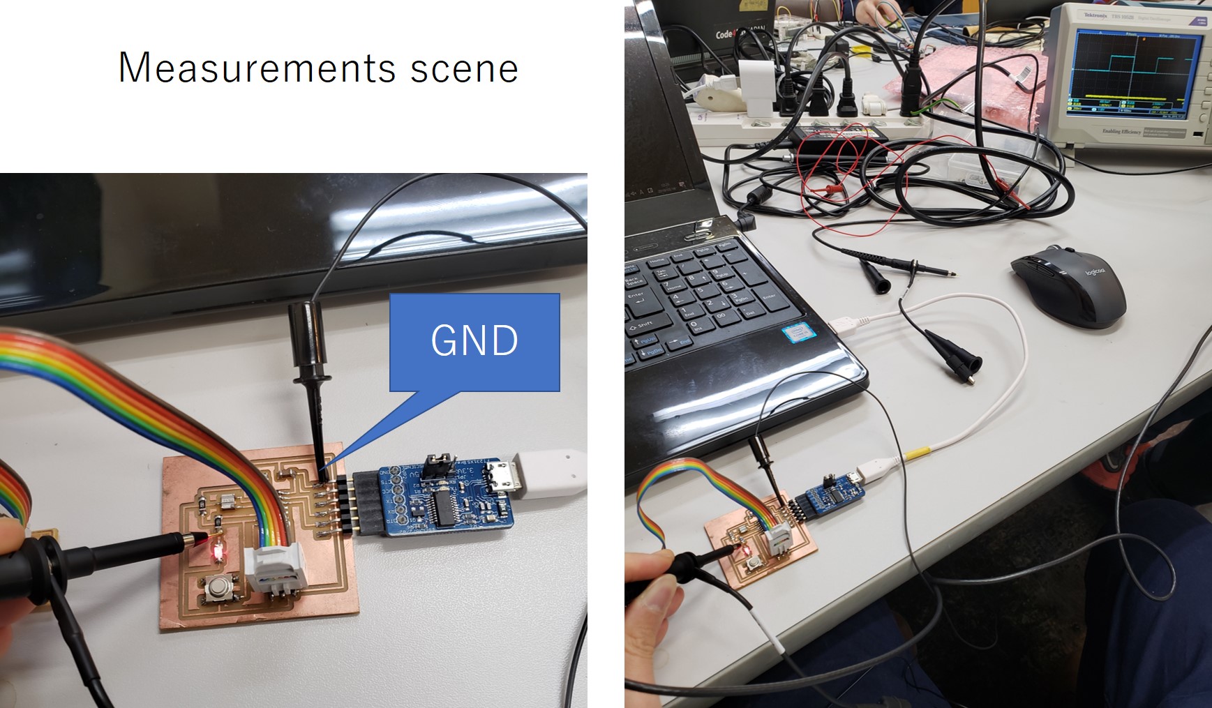
The measured voltage showed the period to blink (= voltage was not 0) was about 8000ms. So, the LED definitely blinked too longer.
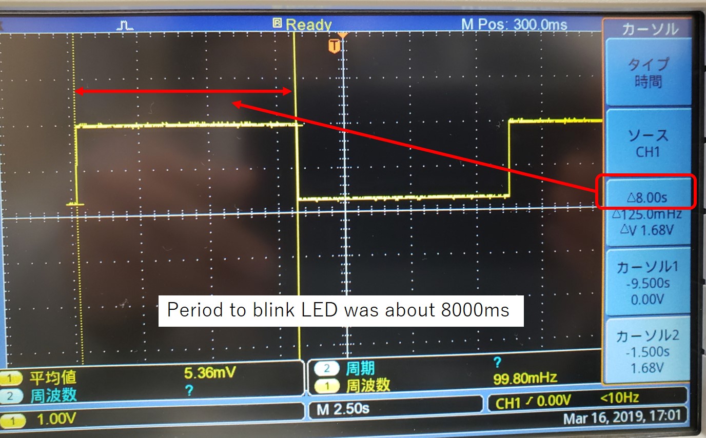
From descriptions in chapter 6.2.6, the initial system in clock Attiny 44 seemed to be prescaling by 8. So, this might cause the period to blinking LED take longer than 1000(ms). Then, I found a code description from the sample code,hello.ftdi.44.echo.c.
CLKPR = (1 << CLKPCE);
CLKPR = (0 << CLKPS3) | (0 << CLKPS2) | (0 << CLKPS1) | (0 << CLKPS0);
When I saw these descriptions in the sample code, I could not understand the meaning of them.
However, I realized them after reading chapter 6.5.2.
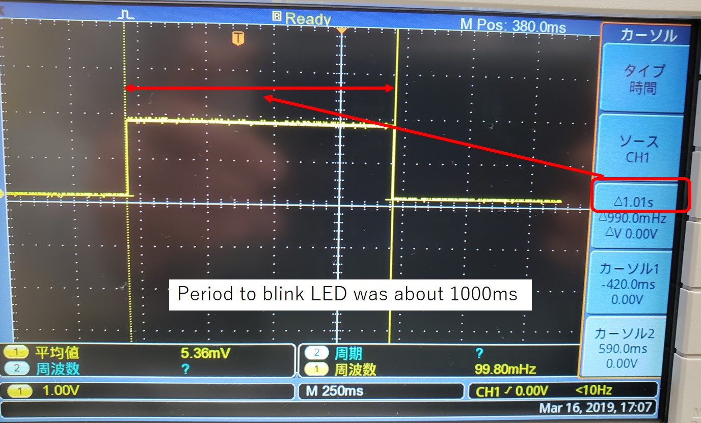
So, I added the above description in my code.
Afetr adding them, period to blink became 1000ms.
Blinking a LED when a button is pressed
Secondly, I tried to combine the LED and switch function.
The desired function was very simple.
When the switch was pressed, the LED would blink.
Added descriptions were shown following.
// For pressing a button
   serial_direction=0b00000000;// All pins in portA are input pins
   serial_port=0b11111111;

   if ((PINA&0b10000000)==0b10000000){
        LED_port=0b0000;
      }
    else{
        LED_port=0b0100;
      }
(PINA&0b10000000) is for “Mask operation”. Mask Operation will make all ineligible bits “0” to extract only desired information. In this case, whether PA7 was HIGH or LOW was required information. So, to extract PA7’s bit inoformation from PINA bits, (PINA&0b10000000) was used.
Blinking a LED the same number of times as one inputted by keyboard
Finally, I tried to make the LED the same number of times as one inputted by a keyboard. One of the reasons to try it was to confirm that I could use the same function as “printf” by using GitBash.
When I wrote simply “printf” in my code, Gitbashdisplayed nothing. Using “printf” is a useful way for me to check where there is something wrong in the codes. In later class and my final project, FabISP may be used, so I thought this method must be necessary also by using Gitbash.
I remembered I used term.py to display some characters, so I would utilize it. Added descriptions were shown below.
static char chr;
static char buffer[max_buffer] = {0};
static int index;

get_char(&serial_pins, serial_pin_in, &chr);
put_string(&serial_port, serial_pin_out, "kota_week9.c: Typed a number of bliking LED is \"");
buffer[0]=chr;
put_string(&serial_port, serial_pin_out, buffer);
put_char(&serial_port, serial_pin_out, '\"');
put_char(&serial_port, serial_pin_out, 10); // new line

int i;
int number=chr-'0';
if (chr>=48 & chr<=57){
    for (i=1;i<=number;i++){
       LED_port=0b0100;
       _delay_ms(1000);
       LED_port=0b0000;
       _delay_ms(1000);

     }
      put_string(&serial_port, serial_pin_out, "Please input next number \"");
      put_char(&serial_port, serial_pin_out, 10); // new line
    }
    else{
      put_string(&serial_port, serial_pin_out, "Please input available char(number) \"");
      put_char(&serial_port, serial_pin_out, 10); // new line
    }
Note: Following three finctions were defined in the smaple code, I did not write detalied codes onf them. If you want to see the detailed descriptions, please download my codes.
get_char(volatile unsigned char *pins, unsigned char pin, char *rxbyte)
put_char(volatile unsigned char *port, unsigned char pin, char txchar)
put_string(volatile unsigned char *port, unsigned char pin, char *str)
In the above code, inputted “character” data types should be converted into “int” types. To do that, the following line was inserted.
int number=chr-'0'
In general, all characters are assigned their unique “int” numbers that are shown in ASCII (below figure). In the figure, for example, “chr” 1 is assigned “int” 49 and “chr” 0 is assigned “int” 48. So, “chr” 1 - “chr” 0= “int” 1.
Programming own board through Arduino board and IDE
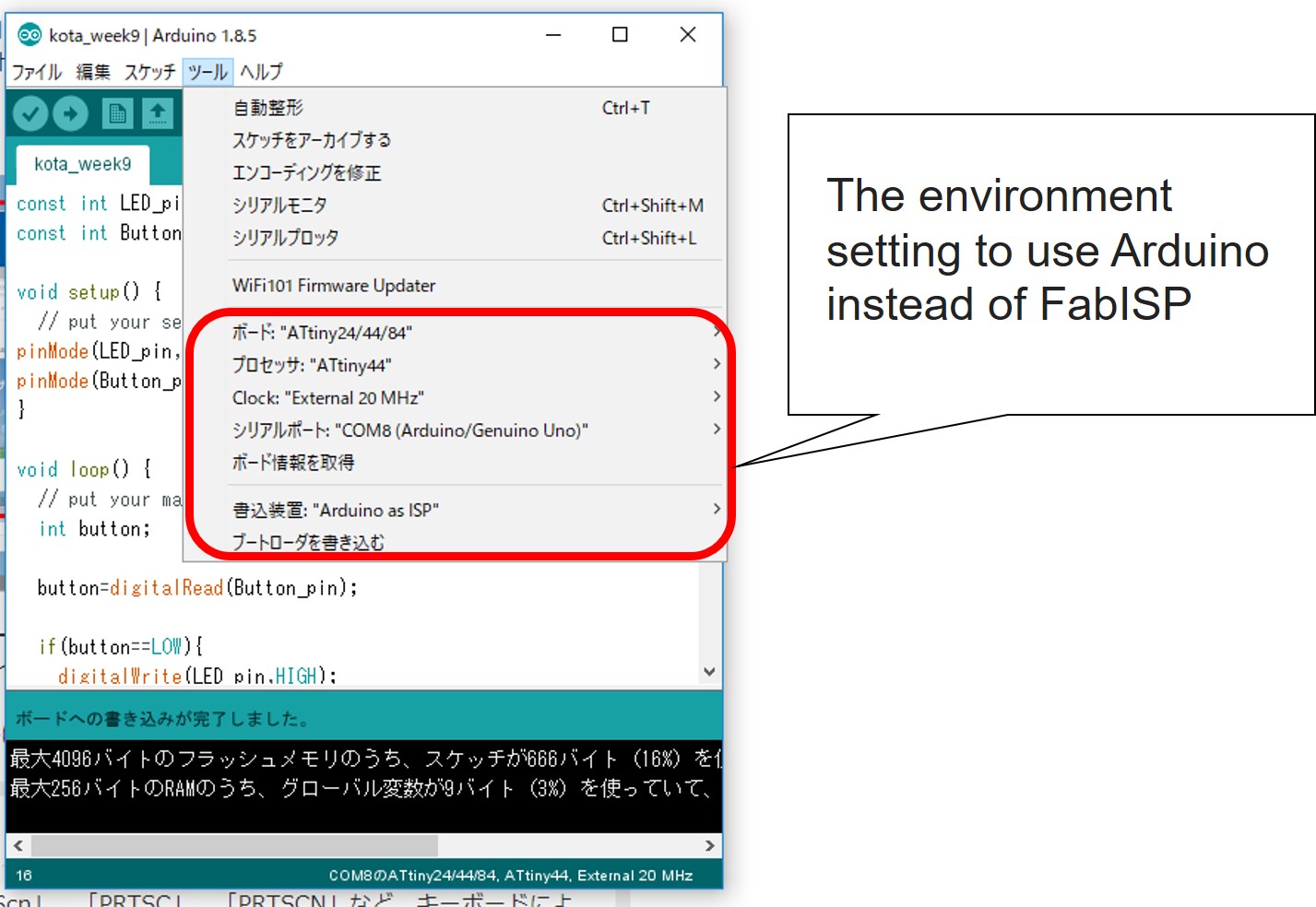
Optionally, I used the Arduino board and IDE to program my own board.
Before programming, I had to import existed Arduino ISP code into the board.
Next, I set up the environment of Arduino to use it instead of FabISP.
Next, I wrote an Arduino code to blink the LED for 1000 ms. The code was shown below.
const int LED_pin=8;
const int Button_pin=7;

void setup() {
  // put your setup code here, to run once:
pinMode(LED_pin,OUTPUT);
pinMode(Button_pin,INPUT);
}

void loop() {
  // put your main code here, to run repeatedly:
  int button;

  button=digitalRead(Button_pin);

  if(button==LOW){
    digitalWrite(LED_pin,HIGH);

    }
  else{
    digitalWrite(LED_pin,LOW);

    }

}
Programming Arduino codes was easier than C language.
The result was shown in following video.